EP0854518A1 - Transistor bipolaire à électrode de grille isolée dans une tranchée - Google Patents
Transistor bipolaire à électrode de grille isolée dans une tranchée Download PDFInfo
- Publication number
- EP0854518A1 EP0854518A1 EP97310639A EP97310639A EP0854518A1 EP 0854518 A1 EP0854518 A1 EP 0854518A1 EP 97310639 A EP97310639 A EP 97310639A EP 97310639 A EP97310639 A EP 97310639A EP 0854518 A1 EP0854518 A1 EP 0854518A1
- Authority
- EP
- European Patent Office
- Prior art keywords
- region
- trench
- type region
- gate electrode
- type
- Prior art date
- Legal status (The legal status is an assumption and is not a legal conclusion. Google has not performed a legal analysis and makes no representation as to the accuracy of the status listed.)
- Withdrawn
Links
Images


Classifications
-
- H—ELECTRICITY
- H10—SEMICONDUCTOR DEVICES; ELECTRIC SOLID-STATE DEVICES NOT OTHERWISE PROVIDED FOR
- H10D—INORGANIC ELECTRIC SEMICONDUCTOR DEVICES
- H10D12/00—Bipolar devices controlled by the field effect, e.g. insulated-gate bipolar transistors [IGBT]
- H10D12/411—Insulated-gate bipolar transistors [IGBT]
- H10D12/441—Vertical IGBTs
- H10D12/461—Vertical IGBTs having non-planar surfaces, e.g. having trenches, recesses or pillars in the surfaces of the emitter, base or collector regions
- H10D12/481—Vertical IGBTs having non-planar surfaces, e.g. having trenches, recesses or pillars in the surfaces of the emitter, base or collector regions having gate structures on slanted surfaces, on vertical surfaces, or in grooves, e.g. trench gate IGBTs
Definitions
- This invention relates to semiconductor devices, and is particularly concerned with trench devices, ie devices in which at least one electrode is set into the wall or bottom or forms part of a trench or recess below a major, usually planar, surface of a semiconductor device.
- trenches are particularly advantageous for devices such as IGBT's (insulated gate bipolar transistors) which are capable of operating at high power and voltage levels.
- IGBT's insulated gate bipolar transistors
- the limit on the upper value of voltage at which such devices can be used is determined by the breakdown voltage of a device.
- it is important that the device has a low on-state resistance and turns-off (ie current flow through the device ceases) promptly and reliably in response to a turn-off signal. It has proved difficult to produce such a device which reliably meets the conflicting requirements of high current, high voltage operation and a safe, reliable current control characteristic.
- the present invention seeks to provide an improved semiconductor device.
- a semiconductor trench device includes an active region having one or more trenches extending from a first surface thereof with at least one p-n junction across which current flow is controllable by a field effect gate electrode disposed at a wall region of the trench and which electrode is operative to produce an inversion layer in a first semiconductor region of a first conductivity type, at least a bottom portion of said trench remote from said first surface being positioned in said first semiconductor region, said first region being adjacent a second semiconductor region of a second conductivity type and which is located between said first region and an anode region which is of said first conductivity type, said gate electrode being operative in use to cause said inversion layer to initiate carrier injection into said first and second regions thereby producing a thyristor action in which the inversion layer, whilst it is present, acts as an emitter thereof.
- a semiconductor trench device includes an active region having one or more trenches extending from a first surface thereof with at least one p-n junction across which current flow is controllable by a field effect gate electrode disposed at a wall region of the trench and which electrode is operative to produce an inversion layer in an adjacent first p type region, at least a bottom portion of said trench remote from said first surface being positioned in said first p type region, said first p type region being adjacent an n type region which is located between said first p type region and an anode second p type region, said gate electrode being operative in use to form the inversion layer adjacent thereto in dependence on a potential applied thereto, thereby causing electron injection into said first p type region and said n type region and a thyristor action in which the inversion layer, whilst it is present, acts as an emitter thereof.
- a semiconductor trench device includes an active region having one or more trenches extending from a first surface thereof with at least one p-n junction across which current flow is controllable by a field effect gate electrode disposed at a wall region of the trench and which electrode is operative to produce an inversion layer in an adjacent first p type region, at least a bottom portion of said trench remote from said first surface being positioned in said first p type region, said first p type region being adjacent a first n type region which is located between said first p type region and an anode second p type region, said gate electrode being operative in use to form the inversion layer adjacent thereto in dependence on a potential applied thereto, thereby causing electron injection into said first p type and said first n type region and current flow to said anode second p type region whilst, and only whilst, said inversion layer is maintained by the field effect of said gate electrode.
- a further n type region which constitutes one side of said p-n junction forms part of the cathode of the device.
- the further n type region is of n+ conductivity type.
- said first n type region is of n- conductivity type.
- the trench cuts through the n+ cathode diffusion, and terminates inside said first p type region.
- a positive potential is applied to the gate electrode, an inversion channel in the form of a layer immediately adjacent to the surface of the trench is produced, and this channel connects with the first n type region (termed an n- base region) located beyond the first p region.
- an electrical path is formed by a thin layer of electrons which joins the cathode second n type region and the n- base region. Electrons are injected into the n- base from the cathode, and as a result, holes are injected from the anode second p type region into the base.
- the inversion layer acts as an emitter of a thyristor-like mechanism.
- this inversion layer exists only whilst an appropriate potential is applied to the trench gate, it may be regarded as a virtual emitter, in that removal of the gate electrode causes the inversion layer to collapse and current conduction between anode and cathode to cease.
- the device therefore is inherently safe in that it can be turned on and off quickly and reliably.
- the bottom of the trench does not penetrate through the p region into the n- base region, the bottom of the trench is protected from the high electric field which exists whilst the device is turned off, ie whilst it is non-conductive.
- the device is intended to operate at voltages in the range 400 volts to in excess of 5000 volts this is a very important consideration, and in fact permits devices of this invention to be safely and reliably used at high voltages.
- a silicon body is provided with a cathode electrode 1 at a first surface 2 thereof and an anode electrode 3 at a second, opposite, surface 4 thereof.
- the silicon body is formed from a flat relatively thin slice of silicon having an n- conductivity type, into which various conductivity modifying materials are introduced to form a succession of electrically different regions.
- the silicon body is formed by the p anode region onto/into which the other regions are grown or diffused.
- the bulk of the device comprises the n- region 5, having relatively thin layers 6 and 7 of n+ and p+ material respectively between it and the anode electrode 3.
- the thin layer 6 is desirable but optional.
- a region 8 of p type material in the form of a well is provided adjacent the first surface 2 into which a trench 9 is formed.
- the trench 9 is a region of doped polysilicon which constitutes a gate electrode which has a thin outer oxide layer 10 positioned between it and the p region 8.
- a small cathode n type region 11 is formed of n+ material at the first surface 2, so that a part of it is in contact with the oxide layer 10, and part in contact with the cathode electrode 1. Thus, one end of the p-n junction so formed between regions 8 and 11 is shorted out by the cathode electrode 1.
- This cathode region in operation constitutes part of the cathode of the device.
- n+ region 13 is formed on the opposite side of the trench 9; this may be convenient from a manufacturing point of view. If it is provided, a separate connection is needed to a further gate electrode region 14 which overlies the junction between the n- base region 5 and the p region 8, and which extends to the n+ region 13.
- This gate region 14 is electrically connected to the gate electrode 9, and is spaced from the body of the semiconductor material by an oxide layer 15.
- a field oxide 16 overlies the surface 2.
- n+ region 13 may be omitted and the further gate electrode region 14 is electrically and physically continuous with the gate electrode 9.
- the operation of the device is as follows.
- a positive potential is applied to the gates 9 and 14 an inversion channel 12 is formed in the adjacent layer of p region 8. Therefore the n+ cathode is connected through the inversion channel to the n-region 5 (via the floating n+ region 13 in the case of Figure 1).
- an electrical path formed by a thin layer of electrons which joins the cathode 11 and the n- base 5 is established.
- Electrons are injected into the n- base from the cathode and as a result holes are injected from the anode p+ region 7 into the n- base 5.
- the buffer layer 6 reduces the hole injection from the p+ region 7 to increase the turn-off speed of the device.
- the concentration in the p region 8 is of the order of 10 15 to 10 16 cm -3
- the thickness of the region between the bottom of the trench 9 and the n- region 5 is of the order of 1 to 3 microns.
- the oxide 10 around the trench 9 may be only 500 ⁇ thick.
- the device During turn-off the inversion layer is removed and therefore the thyristor emitter 12 collapses.
- the device further turns-off like an IGBT.
- the device In the on-state, the device can be regarded as a combination between a thyristor and a Trench IGBT.
- Figure 5 illustrates the potential distribution during the off (ie non-conductive) state at the breakdown voltage of the device.
- the depletion region of the underlying junction does not reach the trench bottom.
- the breakdown voltage is determined by this junction and is not affected by the presence of the trench.
- the design of the p region 8, its doping concentration profile and the distance between the bottom of the p region and the bottom of the trench is a significant parameter in device operation. A small distance between the p region and the bottom of the trench can lead to premature breakdown whereas a large distance can compromise the turn-on of the thyristor structure.
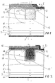
- FIG. 6 A modified structure is shown in Figure 6, in which a buried p region 20 is used.
- a selective implant of the p region 20 is made into the n- base region 21, subsequently followed by an epitaxial growth of the second part of the n-base 22.
- the bottom of the trench penetrates the p+ buried layer 20.
- the trench corners are protected from high electric fields in the off-state by the presence of this p buried layer. Comparing with the structure of Figures 1 and 2 the fabrication process is more complex, however the device offers an improved protection against high electric fields in the off-state (because the p+ buried layer 20 can be more heavily doped than the bottom of the p region 8 of Figures 1 and 2. This eliminates the need for the n+ floating layer 13 and the further gate region 14 of Figure 1.
- n- region 23 can in practice be dispensed with, as shown in Figure 7, in which the upper p+ diffusion reaches the buried p region 20.
- Figure 8 shows a further embodiment in which the trench 9 is associated with two inversion layers.
- the p regions 30, 31 on both sides of the trench cover the trench corners to protect them from high electric fields in the off-state.
- an inversion channel is formed in both of the p regions. Electrons are injected from the cathodes 32, 33 through the n-upper region situated between the p regions.
- the PIN diode formed between the accumulation layer 34, the n- base 5 and p+ anode region 7 is active and in the initial stage the conduction area and the conductivity modulation process at the upper part of the n- base is restricted to the area between the p regions.
- the enhanced conductivity modulation in this region is due to the forward-biassed accumulation layer junction (n+ accumulation layer 34/n- base 5 junction).
- the conductivity modulation area extends significantly over the p regions 30, 31 and both the accumulation layer emitter 34 (as part of the PIN diode) and the inversion layer emitter 12a and 12b (as part of the thyristor) are active.
- this structure has a higher channel density than the previous structures since both sides of the gate have a cathode contact.
- the device shown in Figure 9 is operationally equivalent to that of Figure 8, and differs in that an optional n- layer 40 is positioned to separate the p regions into upper and lower portions 41 and 42.
- a high current device could have a plurality of trench structures operating in parallel.
- Figure 10 shows an arrangement in which a number of trenches 50, 51, 52 are associated with a common p region 53 and a single lateral gate 14, 15.
- the second and subsequent trenches may not fully participate to the conduction, ie the inversion layer junctions associated with the second and subsequent trenches may not be fully forward-biassed.
- a double gate device is shown in Figure 11.
- This device can offer an increased control and a larger safe operating area, but does require a more complex driving circuit to apply signals to the gates.
- the structure has two MOSFET gates termed the DMOS gate (G1) and the trench gate (G2) and associated MOSFET elements 56, 57.
- the device turns on by applying a positive potential on both G1 and G2.
- G1 and G2 are active, the device can be designed to operate in a similar mode to the previously described devices.
- the device switches in the inversion layer injection mode. In this mode the thyristor structure which has the emitter formed by the inversion layer 12 associated with the trench gate is fully operational.
- the device turns off by removing the positive potential on G2 (G1 is already off).
- the inversion layer emitter is quickly removed and the turn-off continues with the process of charge sweeping to the cathode short contact and the relatively slow recombination of carriers at the anode side.
- Figure 12 An alternative form of the invention is shown in Figure 12, which is termed a lateral device. Variations of this configuration are shown in Figures 13 and 14.
- the body of the device can be thin, and if desired can be formed on an insulating substrate.
- the device is formed on a p- substrate 60.
- An n- epitaxial layer 61 is grown onto the p- substrate 60.
- a p well 62 is formed onto the n- epitaxial layer 61 which connects the cathode 64 to the p- substrate 60.
- the gate trench 9 is located in the p region 62.
- the cathode connection is to a localised n+ region 63 having a p-n junction which is electrically shorted by the cathode electrode 64.
- the p+ anode 65 is located at the same major surface of the silicon body as the cathode, and thus the term lateral device is used.
- An n buffer layer 68 is desirable for punch-through protection in the off-state and also to increase the turn-off speed.
- n+ buried layer 66 (shown in Figure 13) can be used to narrow the path between the channel and the p- substrate 60, to facilitate the triggering of the thyristor with the emitter formed by the inversion layer 12.
- Figure 14 depicts an insulating layer 70, in this case an oxide, overlying a silicon substrate 71, as known in the state of the art of Silicon on Insulator technology.
- insulating layer 70 in this case an oxide
- Other Dielectric Isolation (DI) technologies such as Silicon on Sapphire (SOS) may also be used.
- DI Dielectric Isolation
- SOS Silicon on Sapphire
- the advantage of this structure is the absence of the current through the p-substrate which results in a more effective triggering of the inversion layer thyristor (the hole current at the cathode side is constricted to flow only between the oxide layer and the trench gate) and in addition eliminates the undesirable charge stored in the substrate.
- the recombination of holes with electrons in the inversion layer also leads to a reduced hole current reaching the cathode contact thus reducing the latch-up effect and improving the forward biassed safe operating area.
- the device also exhibits a high immunity against static and dynamic latch-up due to the use of the trench gate.
- the trench body is situated inside the relatively highly doped p region and therefore is protected against high electric fields in the blocking mode.
- structures of the kind shown in Figures 12, 13 and 14 typically many trenches would be provided in a single device and as the trenches are far from each other, the problem of high electric fields at the bottom corners would be severe, but by using the inversion layer injection concept in such devices and therefore placing the trench body inside the p region this problem is largely overcome.
- the device has only three terminals, easy gate control, reduced latch-up effect, wide safe operating area and enhanced geometrical carrier distribution at the cathode side approaching that of a thyristor.
- FIGS 16, 17 and 18 Further modifications of the lateral structure are shown in Figures 16, 17 and 18 in which the anode is provided with an additional n+ surface region 72 such that the p-n junction formed between it and the p+ anode is electrically shorted by the anode electrode.
- the reduction in the anode injection efficiency and the collection of electron charge during turn-off results however in very fast turn-off.
Landscapes
- Thyristors (AREA)
Applications Claiming Priority (2)
| Application Number | Priority Date | Filing Date | Title |
|---|---|---|---|
| GB9701210 | 1997-01-21 | ||
| GB9701210A GB2321337B (en) | 1997-01-21 | 1997-01-21 | Improvements in or relating to semiconductor devices |
Publications (1)
| Publication Number | Publication Date |
|---|---|
| EP0854518A1 true EP0854518A1 (fr) | 1998-07-22 |
Family
ID=10806357
Family Applications (1)
| Application Number | Title | Priority Date | Filing Date |
|---|---|---|---|
| EP97310639A Withdrawn EP0854518A1 (fr) | 1997-01-21 | 1997-12-29 | Transistor bipolaire à électrode de grille isolée dans une tranchée |
Country Status (4)
| Country | Link |
|---|---|
| US (1) | US6091107A (fr) |
| EP (1) | EP0854518A1 (fr) |
| JP (1) | JPH10209432A (fr) |
| GB (1) | GB2321337B (fr) |
Cited By (7)
| Publication number | Priority date | Publication date | Assignee | Title |
|---|---|---|---|---|
| US7705368B2 (en) | 2006-03-24 | 2010-04-27 | Fujifilm Corporation | Insulated gate type thyristor |
| US7948005B2 (en) | 2007-05-17 | 2011-05-24 | Hitachi, Ltd. | Insulated-gate bipolar transistor (IGBT) |
| WO2013049850A2 (fr) | 2011-09-29 | 2013-04-04 | Pakal Technologies Llc | Dispositif mct à états de verrouillage et de non-verrouillage déterminés par largeur de base |
| WO2013056251A1 (fr) | 2011-10-14 | 2013-04-18 | Pakal Technologies Llc | Systèmes, dispositifs et procédés utilisant des thyristors latéraux commandés par des tec intégrables |
| CN108022972A (zh) * | 2016-11-02 | 2018-05-11 | 全球能源互联网研究院 | 一种低通态压降igbt及其控制方法、制造方法 |
| GB2592928A (en) * | 2020-03-10 | 2021-09-15 | Mqsemi Ag | Insulated gate switched transistor |
| GB2602663A (en) * | 2021-01-11 | 2022-07-13 | Mqsemi Ag | Semiconductor device |
Families Citing this family (25)
| Publication number | Priority date | Publication date | Assignee | Title |
|---|---|---|---|---|
| KR100295063B1 (ko) * | 1998-06-30 | 2001-08-07 | 김덕중 | 트렌치게이트구조의전력반도체장치및그제조방법 |
| US6373098B1 (en) * | 1999-05-25 | 2002-04-16 | Fairchild Semiconductor Corporation | Trench-gated device having trench walls formed by selective epitaxial growth and process for forming device |
| TW419822B (en) * | 1999-07-12 | 2001-01-21 | Mosel Vitelic Inc | Trench type non-volatile memory cell and its manufacturing method |
| US6380569B1 (en) * | 1999-08-10 | 2002-04-30 | Rockwell Science Center, Llc | High power unipolar FET switch |
| JP4371521B2 (ja) * | 2000-03-06 | 2009-11-25 | 株式会社東芝 | 電力用半導体素子およびその製造方法 |
| JP4738562B2 (ja) * | 2000-03-15 | 2011-08-03 | 三菱電機株式会社 | 半導体装置の製造方法 |
| JP3764343B2 (ja) * | 2001-02-28 | 2006-04-05 | 株式会社東芝 | 半導体装置の製造方法 |
| JP2006344759A (ja) * | 2005-06-08 | 2006-12-21 | Sharp Corp | トレンチ型mosfet及びその製造方法 |
| DE102006024504B4 (de) * | 2006-05-23 | 2010-09-02 | Infineon Technologies Austria Ag | Leistungshalbleiterbauelement mit vertikaler Gatezone und Verfahren zur Herstellung desselben |
| US20100117153A1 (en) * | 2008-11-07 | 2010-05-13 | Honeywell International Inc. | High voltage soi cmos device and method of manufacture |
| US9048282B2 (en) * | 2013-03-14 | 2015-06-02 | Alpha And Omega Semiconductor Incorporated | Dual-gate trench IGBT with buried floating P-type shield |
| CN102169893B (zh) * | 2011-03-10 | 2012-12-05 | 杭州电子科技大学 | 一种具有p埋层的横向沟道soi ligbt器件单元 |
| CN102157550B (zh) * | 2011-03-10 | 2012-07-04 | 杭州电子科技大学 | 一种具有p埋层的纵向沟道SOI LIGBT器件单元 |
| US9306048B2 (en) * | 2012-10-01 | 2016-04-05 | Pakal Technologies Llc | Dual depth trench-gated mos-controlled thyristor with well-defined turn-on characteristics |
| US8878238B2 (en) | 2012-10-01 | 2014-11-04 | Pakal Technologies Llc | MCT device with base-width-determined latching and non-latching states |
| CN104969357B (zh) * | 2013-02-05 | 2019-02-01 | 三菱电机株式会社 | 绝缘栅型碳化硅半导体装置及其制造方法 |
| JP6182921B2 (ja) * | 2013-03-21 | 2017-08-23 | 富士電機株式会社 | Mos型半導体装置 |
| CN104952920A (zh) * | 2015-06-30 | 2015-09-30 | 淄博美林电子有限公司 | 一种沟槽式igbt芯片 |
| WO2017114235A1 (fr) * | 2015-12-28 | 2017-07-06 | 电子科技大学 | Transistor bipolaire latéral à grille isolée et procédé d'élimination de courant de queue de transistor |
| CN105932055B (zh) * | 2016-06-13 | 2018-08-31 | 电子科技大学 | 一种平面栅igbt及其制作方法 |
| JP6847007B2 (ja) * | 2017-09-13 | 2021-03-24 | 株式会社日立製作所 | 半導体装置およびその製造方法 |
| US11245016B2 (en) | 2020-01-31 | 2022-02-08 | Alpha And Omega Semiconductor (Cayman) Ltd. | Silicon carbide trench semiconductor device |
| US11362179B2 (en) | 2020-07-21 | 2022-06-14 | Icemos Technology Ltd. | Radiation hardened high voltage superjunction MOSFET |
| US20220238698A1 (en) * | 2021-01-26 | 2022-07-28 | Pakal Technologies, Inc. | Mos-gated trench device using low mask count and simplified processing |
| US11776994B2 (en) | 2021-02-16 | 2023-10-03 | Alpha And Omega Semiconductor International Lp | SiC MOSFET with reduced channel length and high Vth |
Citations (5)
| Publication number | Priority date | Publication date | Assignee | Title |
|---|---|---|---|---|
| JPS62198160A (ja) * | 1986-02-25 | 1987-09-01 | Fuji Electric Co Ltd | 絶縁ゲ−ト電界効果トランジスタ |
| JPH0690002A (ja) * | 1992-09-09 | 1994-03-29 | Mitsubishi Electric Corp | トレンチ絶縁ゲート型バイポーラトランジスタおよびその製造方法 |
| EP0651507A2 (fr) * | 1993-10-28 | 1995-05-03 | Fuji Electric Co., Ltd. | Dispositif de commande pour dispositif semi-conducteur à double grille |
| DE19501556A1 (de) * | 1994-01-20 | 1995-07-27 | Mitsubishi Electric Corp | Halbleitervorrichtung mit Grabenstruktur und Herstellungsverfahren einer solchen |
| EP0750351A2 (fr) * | 1995-06-19 | 1996-12-27 | Siemens Aktiengesellschaft | Dispositif semi-conducteur de type MOS avec des caractéristiques à l'état passant améliorées |
Family Cites Families (5)
| Publication number | Priority date | Publication date | Assignee | Title |
|---|---|---|---|---|
| TW399774U (en) * | 1989-07-03 | 2000-07-21 | Gen Electric | FET, IGBT and MCT structures to enhance operating characteristics |
| DE69233105T2 (de) * | 1991-08-08 | 2004-05-06 | Kabushiki Kaisha Toshiba, Kawasaki | Bipolartransistor mit isoliertem Graben-Gate |
| JP2837033B2 (ja) * | 1992-07-21 | 1998-12-14 | 三菱電機株式会社 | 半導体装置及びその製造方法 |
| GB9313843D0 (en) * | 1993-07-05 | 1993-08-18 | Philips Electronics Uk Ltd | A semiconductor device comprising an insulated gate field effect transistor |
| US5488236A (en) * | 1994-05-26 | 1996-01-30 | North Carolina State University | Latch-up resistant bipolar transistor with trench IGFET and buried collector |
-
1997
- 1997-01-21 GB GB9701210A patent/GB2321337B/en not_active Expired - Fee Related
- 1997-12-29 EP EP97310639A patent/EP0854518A1/fr not_active Withdrawn
-
1998
- 1998-01-19 JP JP10021415A patent/JPH10209432A/ja active Pending
- 1998-01-20 US US09/009,230 patent/US6091107A/en not_active Expired - Lifetime
Patent Citations (5)
| Publication number | Priority date | Publication date | Assignee | Title |
|---|---|---|---|---|
| JPS62198160A (ja) * | 1986-02-25 | 1987-09-01 | Fuji Electric Co Ltd | 絶縁ゲ−ト電界効果トランジスタ |
| JPH0690002A (ja) * | 1992-09-09 | 1994-03-29 | Mitsubishi Electric Corp | トレンチ絶縁ゲート型バイポーラトランジスタおよびその製造方法 |
| EP0651507A2 (fr) * | 1993-10-28 | 1995-05-03 | Fuji Electric Co., Ltd. | Dispositif de commande pour dispositif semi-conducteur à double grille |
| DE19501556A1 (de) * | 1994-01-20 | 1995-07-27 | Mitsubishi Electric Corp | Halbleitervorrichtung mit Grabenstruktur und Herstellungsverfahren einer solchen |
| EP0750351A2 (fr) * | 1995-06-19 | 1996-12-27 | Siemens Aktiengesellschaft | Dispositif semi-conducteur de type MOS avec des caractéristiques à l'état passant améliorées |
Non-Patent Citations (3)
| Title |
|---|
| LEE B -H ET AL: "A TRENCH-GATE SILICON-ON-INSULATOR LATERAL INSULATED GATE BIPOLAR TRANSISTOR WITH THE P+ CATHODE WELL", JAPANESE JOURNAL OF APPLIED PHYSICS, vol. 34, no. 2B, PART 01, February 1995 (1995-02-01), pages 854 - 859, XP000599410 * |
| PATENT ABSTRACTS OF JAPAN vol. 012, no. 049 (E - 582) 13 February 1988 (1988-02-13) * |
| PATENT ABSTRACTS OF JAPAN vol. 018, no. 350 (E - 1572) 30 June 1994 (1994-06-30) * |
Cited By (12)
| Publication number | Priority date | Publication date | Assignee | Title |
|---|---|---|---|---|
| US7705368B2 (en) | 2006-03-24 | 2010-04-27 | Fujifilm Corporation | Insulated gate type thyristor |
| US7948005B2 (en) | 2007-05-17 | 2011-05-24 | Hitachi, Ltd. | Insulated-gate bipolar transistor (IGBT) |
| WO2013049850A2 (fr) | 2011-09-29 | 2013-04-04 | Pakal Technologies Llc | Dispositif mct à états de verrouillage et de non-verrouillage déterminés par largeur de base |
| EP2761661A4 (fr) * | 2011-09-29 | 2015-07-15 | Pakal Technologies Llc | Dispositif mct à états de verrouillage et de non-verrouillage déterminés par largeur de base |
| WO2013056251A1 (fr) | 2011-10-14 | 2013-04-18 | Pakal Technologies Llc | Systèmes, dispositifs et procédés utilisant des thyristors latéraux commandés par des tec intégrables |
| EP2766933A4 (fr) * | 2011-10-14 | 2015-06-17 | Pakal Technologies Llc | Systèmes, dispositifs et procédés utilisant des thyristors latéraux commandés par des tec intégrables |
| CN108022972A (zh) * | 2016-11-02 | 2018-05-11 | 全球能源互联网研究院 | 一种低通态压降igbt及其控制方法、制造方法 |
| CN108022972B (zh) * | 2016-11-02 | 2021-07-23 | 全球能源互联网研究院 | 一种低通态压降igbt及其控制方法、制造方法 |
| GB2592928A (en) * | 2020-03-10 | 2021-09-15 | Mqsemi Ag | Insulated gate switched transistor |
| GB2592928B (en) * | 2020-03-10 | 2025-01-29 | Mqsemi Ag | Insulated gate switched transistor |
| GB2602663A (en) * | 2021-01-11 | 2022-07-13 | Mqsemi Ag | Semiconductor device |
| GB2602663B (en) * | 2021-01-11 | 2024-09-04 | Mqsemi Ag | Semiconductor device |
Also Published As
| Publication number | Publication date |
|---|---|
| GB2321337A (en) | 1998-07-22 |
| JPH10209432A (ja) | 1998-08-07 |
| US6091107A (en) | 2000-07-18 |
| GB2321337B (en) | 2001-11-07 |
| GB9701210D0 (en) | 1997-03-12 |
Similar Documents
| Publication | Publication Date | Title |
|---|---|---|
| US6091107A (en) | Semiconductor devices | |
| US6051850A (en) | Insulated gate bipolar junction transistors having built-in freewheeling diodes therein | |
| CA2286699C (fr) | Transistor bipolaire mos de puissance sans verrouillage a l'etat passant | |
| US5969378A (en) | Latch-up free power UMOS-bipolar transistor | |
| EP0280535B1 (fr) | Transistor à effet de champ du type MOS à modulation de la conductivité | |
| US7696600B2 (en) | IGBT device and related device having robustness under extreme conditions | |
| US6303410B1 (en) | Methods of forming power semiconductor devices having T-shaped gate electrodes | |
| JP4581179B2 (ja) | 絶縁ゲート型半導体装置 | |
| US4969028A (en) | Gate enhanced rectifier | |
| US5719411A (en) | Three-terminal MOS-gate controlled thyristor structures with current saturation characteristics | |
| US6133607A (en) | Semiconductor device | |
| US10923578B2 (en) | Semiconductor device comprising a barrier region | |
| CN102403341A (zh) | 横向绝缘栅双极晶体管 | |
| US6259134B1 (en) | Trench thyristor with improved breakdown voltage characteristics | |
| EP0228107B1 (fr) | Transistors latéraux à grille isolée commutant rapidement | |
| CN115483281B (zh) | 逆导型横向绝缘栅双极型晶体管 | |
| EP0615292A1 (fr) | Transistor bipolaire à grille isolée | |
| US9806152B2 (en) | Vertical insulated gate turn-off thyristor with intermediate p+ layer in p-base | |
| EP0338312B1 (fr) | Transistor bipolaire à grille isolée | |
| KR100278526B1 (ko) | 반도체 소자 | |
| GB2305777A (en) | Base resistance controlled thyristor structure with high density layout for increased current capacity | |
| US5587595A (en) | Lateral field-effect-controlled semiconductor device on insulating substrate | |
| US5998811A (en) | Trench emitter controlled thyristor | |
| CN119451143B (zh) | 一种igbt结构及半导体器件 | |
| CN119584565B (zh) | 一种igbt结构及其制造方法、半导体器件 |
Legal Events
| Date | Code | Title | Description |
|---|---|---|---|
| PUAI | Public reference made under article 153(3) epc to a published international application that has entered the european phase |
Free format text: ORIGINAL CODE: 0009012 |
|
| AK | Designated contracting states |
Kind code of ref document: A1 Designated state(s): AT DE ES FR GB IT |
|
| AX | Request for extension of the european patent |
Free format text: AL;LT;LV;MK;RO;SI |
|
| RAP1 | Party data changed (applicant data changed or rights of an application transferred) |
Owner name: MITEL SEMICONDUCTOR LIMITED |
|
| 17P | Request for examination filed |
Effective date: 19990122 |
|
| AKX | Designation fees paid |
Free format text: AT DE ES FR GB IT |
|
| RBV | Designated contracting states (corrected) |
Designated state(s): AT DE ES FR GB IT |
|
| RAP1 | Party data changed (applicant data changed or rights of an application transferred) |
Owner name: DYNEX SEMICONDUCTOR LIMITED |
|
| 17Q | First examination report despatched |
Effective date: 20020215 |
|
| STAA | Information on the status of an ep patent application or granted ep patent |
Free format text: STATUS: THE APPLICATION HAS BEEN WITHDRAWN |
|
| 18W | Application withdrawn |
Effective date: 20030311 |