EP0855258A2 - Installation de roto-moulage - Google Patents
Installation de roto-moulage Download PDFInfo
- Publication number
- EP0855258A2 EP0855258A2 EP98101444A EP98101444A EP0855258A2 EP 0855258 A2 EP0855258 A2 EP 0855258A2 EP 98101444 A EP98101444 A EP 98101444A EP 98101444 A EP98101444 A EP 98101444A EP 0855258 A2 EP0855258 A2 EP 0855258A2
- Authority
- EP
- European Patent Office
- Prior art keywords
- mold carrier
- sintering furnace
- rotary molding
- molding machine
- machine according
- Prior art date
- Legal status (The legal status is an assumption and is not a legal conclusion. Google has not performed a legal analysis and makes no representation as to the accuracy of the status listed.)
- Granted
Links
Images


Classifications
-
- B—PERFORMING OPERATIONS; TRANSPORTING
- B29—WORKING OF PLASTICS; WORKING OF SUBSTANCES IN A PLASTIC STATE IN GENERAL
- B29C—SHAPING OR JOINING OF PLASTICS; SHAPING OF MATERIAL IN A PLASTIC STATE, NOT OTHERWISE PROVIDED FOR; AFTER-TREATMENT OF THE SHAPED PRODUCTS, e.g. REPAIRING
- B29C41/00—Shaping by coating a mould, core or other substrate, i.e. by depositing material and stripping-off the shaped article; Apparatus therefor
- B29C41/02—Shaping by coating a mould, core or other substrate, i.e. by depositing material and stripping-off the shaped article; Apparatus therefor for making articles of definite length, i.e. discrete articles
- B29C41/04—Rotational or centrifugal casting, i.e. coating the inside of a mould by rotating the mould
- B29C41/06—Rotational or centrifugal casting, i.e. coating the inside of a mould by rotating the mould about two or more axes
-
- B—PERFORMING OPERATIONS; TRANSPORTING
- B29—WORKING OF PLASTICS; WORKING OF SUBSTANCES IN A PLASTIC STATE IN GENERAL
- B29C—SHAPING OR JOINING OF PLASTICS; SHAPING OF MATERIAL IN A PLASTIC STATE, NOT OTHERWISE PROVIDED FOR; AFTER-TREATMENT OF THE SHAPED PRODUCTS, e.g. REPAIRING
- B29C33/00—Moulds or cores; Details thereof or accessories therefor
- B29C33/34—Moulds or cores; Details thereof or accessories therefor movable, e.g. to or from the moulding station
-
- B—PERFORMING OPERATIONS; TRANSPORTING
- B29—WORKING OF PLASTICS; WORKING OF SUBSTANCES IN A PLASTIC STATE IN GENERAL
- B29C—SHAPING OR JOINING OF PLASTICS; SHAPING OF MATERIAL IN A PLASTIC STATE, NOT OTHERWISE PROVIDED FOR; AFTER-TREATMENT OF THE SHAPED PRODUCTS, e.g. REPAIRING
- B29C41/00—Shaping by coating a mould, core or other substrate, i.e. by depositing material and stripping-off the shaped article; Apparatus therefor
- B29C41/34—Component parts, details or accessories; Auxiliary operations
- B29C41/46—Heating or cooling
-
- Y—GENERAL TAGGING OF NEW TECHNOLOGICAL DEVELOPMENTS; GENERAL TAGGING OF CROSS-SECTIONAL TECHNOLOGIES SPANNING OVER SEVERAL SECTIONS OF THE IPC; TECHNICAL SUBJECTS COVERED BY FORMER USPC CROSS-REFERENCE ART COLLECTIONS [XRACs] AND DIGESTS
- Y10—TECHNICAL SUBJECTS COVERED BY FORMER USPC
- Y10S—TECHNICAL SUBJECTS COVERED BY FORMER USPC CROSS-REFERENCE ART COLLECTIONS [XRACs] AND DIGESTS
- Y10S425/00—Plastic article or earthenware shaping or treating: apparatus
- Y10S425/20—Molding plants
- Y10S425/201—Diverse stations
Definitions
- the present invention relates to a rotary molding machine with a sintering furnace, at least one cooling chamber and at least a means of transport for receiving at least one Shaped body and for its transport between the sintering furnace and the at least one cooling chamber.
- Such systems are used to manufacture hollow plastic bodies in hollow molds that are held by the mold carrier.
- the hollow molds filled with plastic powder or sinter powder and in the sintering furnace heated by performing a rotational movement. After Melting and even distribution of the powder in the The mold carrier is made hollow by the means of transport Cooling chamber spent where continuing a rotational movement the mold is cooled.
- a generic rotary molding machine is from UK 1 334 331 known.
- the system described has a circular shape rotating transport means arranged cooling chambers and one Sintering furnace.
- the one that works like a carousel Transport means has four arms for receiving mold carriers on by a rotational movement of the means of transport between the individual stages of the manufacturing process be moved.
- the sintering furnace can be moved in the radial direction, around one of the mold carriers attached to the arms enclose.
- the sintering furnace surrounds during the melting process the mold carrier only from five sides; a flap of the Sintering furnace must be caused by the during the melting process rigid arm of the means of transport remain open, resulting in high Energy losses result during the melting process.
- a rotary molding machine is known from EP 01 77 906 A2, in which a number of cooling chambers are circular around a sintering furnace is arranged and on as a means of transport Rails movable between the cooling chambers and the sintering furnace Tool carrier is used.
- the system has the disadvantage that they are due to the circular arrangement of the cooling chambers around the sintering furnace is very space consuming and that the heating chamber must either be dimensioned so large that the mold carrier including means of transport or that here too the sintering furnace with some remaining outside Means of transport cannot be closed completely.
- Another generic device is made of: wildfire, E .: "Rotation forms - process engineering overview", plastics and Kautschuk, 21. vol., Issue 3, 1974, pp. 203 to 207.
- a rotary system in series described a heating chamber arranged cooling chambers, wherein serve as a means of transport tool carrier on a Rail can be moved next to the cooling chambers and the heating chamber and which telescopic arms for inserting a rotary molding tool into the cooling chambers or the heating chamber exhibit.
- the heating chamber is completely closed not due to the telescopic arm of the means of transport possible.
- so many means of transport are always required how mold carriers are in the manufacturing process.
- the aim of the present invention is therefore a rotary molding system to make available to realize the space-saving is and the optimal use of the supplied Energy works. Furthermore, those for the known Rotation molding machines described disadvantages can be avoided.
- This goal is achieved by a rotary molding system described at the beginning solved, in which the sintering furnace and at least a cooling chamber first rotating devices for receiving the mold carrier exhibit.
- the mold carrier can be completely in the sintering furnace or Cooling chambers introduced and the sintering furnace or the cooling chambers can completely during the melting or cooling process getting closed.
- the latter aspect creates an optimal one Utilization of the energy used for heating or cooling.
- the means of transport used for transport of the mold carrier between the cooling chambers and the sintering furnace is used to transport other form carriers, while a mold carrier is currently in the sintering furnace or in the Cooling chamber is located. This helps reduce overall costs the rotary molding machine.
- the sintering furnace and two cooling chambers are advantageous and a demolding station arranged in series. This results in a particularly space-saving implementation the rotary molding machine according to the invention.
- the space requirement can be according to another embodiment be further reduced in that the means of transport as Mold carrier carriage is formed, which is below the sintering furnace and the at least one cooling chamber is movable. Out of this results in a rotary molding machine with a minimal footprint, those available to the top in modern manufacturing facilities uses standing space.
- the mold carrier carriage has one Lifting device up to the mold carrier from below into the sintering furnace or to introduce the cooling chambers. Since the sintering furnace for Insertion of the mold carrier to be opened from below escapes less heat than when opening on one of the other sides would be the case. This proves to be another advantage this embodiment.
- the system described offers the Possibility of using different shapes in the same system Process duration to be treated, since a mold carrier is in the process flow can overtake the other. This is an optimal utilization the system guaranteed.
- the sintering furnace is rotatably supported by means of a second rotating device, a second predetermined by the second rotating device Axis of rotation and a through the first receiving the mold carrier Rotation device predetermined first axis of rotation not parallel run.
- the mold carrier thus executes through its own rotation and the rotation of the sintering furnace in the sintering furnace is a rotational movement, an optimal distribution of the melted Powder inside the one held by the mold carrier Cavity causes.
- the first rotating devices have to accommodate the mold carrier the sintering furnace or the cooling chambers, who attack on opposite sides of the mold carrier and which extend the first axes of rotation, especially pneumatically, are movable to clamp the form carrier or to release. At least one of the two clamping elements is driven by an electric motor to rotate the mold carrier. For establishing a torque-locking connection between this clamping element and the mold carrier Clamping element on the front approaches and / or recesses that on corresponding recesses and / or approaches of the mold carrier attack for torque transmission.
- the mold carrier carriage also has a rotating device to the mold carrier during transportation from the sintering furnace to keep the cooling chambers rotating.
- Figures 1 and 2 is a rotary molding system according to the invention in side view ( Figure 1) and top view ( Figure 2) shown.
- the rotary molding system has a sintering furnace 1 and two cooling chambers 8, 9 arranged in series therewith.
- a demolding station 12 which is used for Provision of new mold carriers and for demoulding the mold carriers or the hollow molds after the cooling process has been completed serves.
- a control cabinet 80 is provided for completeness shown, which is required to control the system Electronics.
- the sintering furnace 1, the cooling chambers 8, 9 and the demolding station 12 have first rotating devices 3, 10, 11, 13 for rotating Inclusion of a mold carrier 6, which is used to manufacture of hollow objects required by plastic objects.
- the structure and operation of the identical first turning devices 3, 10, 11, 13 takes place in detail using the first Rotary device of the sintering furnace 1 in FIGS. 4 and 5.
- the sintering furnace 1 and the cooling chambers 8, 9 are on supports 30, 86, 96 stored, whereby a mold carrier 5, which is used for transport of the mold carrier 6 between the demolding station 12, the Sintering furnace 1 and the cooling chambers 8, 9 serves on a rail 100 can be moved below the sintering furnace and the cooling chambers 8, 9 is.
- the mold carrier carriage 5 points to the rail 100 attacking wheels 58 and one in Figures 1 and 2 not closer shown lifting device, by means of which the mold carrier 6 from below into the sintering furnace 1 or the cooling chambers 8, 9 introduced and after completion of the sintering or cooling process is removable again.
- the dash-dotted circles in Figure 1 and the dash-dotted rectangles in Figure 2 indicate the position of a mold carrier having maximum dimensions below or within the sintering furnace 1 and Cooling chambers 8, 9 and in the demolding station 12.
- Blowers 82, 92 are arranged on the cooling chambers 8, 9 Suck air, which via air outlet nozzles 84, 94 into the interior the cooling chambers 8, 9 are blown in to cool a mold carrier becomes.
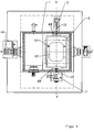
- Figures 3 to 5 show a more detailed representation of the Sintering furnace 1 and the device supporting it in two Side views and in plan view, one in FIG Mold carrier 6 on the mold carrier carriage 5 outside the sintering furnace 1 and in Figures 4 and 5 within the sintering furnace 1 is located.
- the mold carrier 6 consists in the examples shown a rectangular frame in which by means of struts 66 a hollow mold 62 is held. On two opposite A circular disk 64, 64 'is attached to each side, for the rotatable mounting of the mold carrier 6 on four rollers 56, 56 ', 58 of the mold carrier carriage 5 is used.
- Figure 6 shows one lateral representation of the placed on the mold carrier 5 Mold carrier 6.
- the mold carrier 5 has a rotating device to carry out a rotational movement of the mold carrier 6 on the rollers 56, 56 ', 58.
- the rotating device of the Mold carrier carriage 5 has a drive motor 59 which a chain 53 one of the rollers 56 'on which the mold carrier 6 by means of the disks 64, 64 ', drives.
- the mold carrier 5 also has a lifting device 52, by means of which the mold carrier 6 from below be introduced into the sintering furnace 1 and removed can.
- An opening of the sintering furnace 1 for taking in or taking out the mold carrier 6 is by means of an electric motor actuatable flap 2, 2 'closable, the closed in Figure 3 Position (2) and open position (2 ') shown is.
- the sintering furnace 1 has a rotating device 3 for receiving of the mold carrier 6, with this rotating device 3 corresponding Rotating devices 10, 11, 13 in the in the figures 1 and 2 shown cooling chambers 8, 9 and the demolding station 12 are available.
- the rotating device 3 has in particular pneumatically displaceable along a first axis of rotation B-B ' first and second clamping elements 32, 34 for receiving the mold carrier 6.
- the second clamping element 34 has an end face disc-like element 36 with lugs, these lugs in corresponding recesses 65 'of the disk 64' of Intervene mold carrier 6 to produce a torque lock.
- On the representation of the sprocket explained in Figure 6 51 is in the figures for the sake of clarity 4 and 5 waived.
- the sprocket 51 has a recess , whereby the disc-like element 36 on the disc 64 ' can attack.
- the second clamping element 34 is an electric motor driven to the mold carrier 6 after torque with the second clamping element 34 into a rotational movement to move the axis of rotation B-B '.
- the first clamping element 32 engages in a recess 65 of the circular face Washer 64 of the mold carrier 6 to be together with the second Clamping element 34 to hold the mold carrier 6.
- the mold carrier 6 is by means of the mold carrier 5 under the sinter furnace 1 already opened. By means of the lifting device 52, the mold carrier 6 is raised until it is on is at a height at which the clamping elements 32, 34 on the engage corresponding recesses 65, 65 'of the mold carrier 6 can.
- the clamping elements 32, 34 are now pneumatically in pressed axially against the mold carrier 6, which first clamping element 32 in the corresponding recess 65 of the Mold carrier 6 engages.
- a rotation of the second follows Clamping element 34 to the approaches of the end plate 36 in the Engage recesses 65 'of the mold carrier 6.
- the mold carrier 6 is held by the two clamping elements 32, 34 which Lifting device 52 is then lowered and the flap 2 is closed.
- the flap will open 2 opened, the lifting device 52 extended until the two disks 64, 64 'of the mold carrier 6 on the rollers 56, 56 ', 58 of the holding device 54 of the mold carrier carriage 5 rest.
- the clamping elements 32, 34 are when the molded body is rotating 6 withdrawn to release the mold carrier 6.
- the Rotational movement of the mold carrier 6 is now by the electromotive Rotating device of the mold carrier carriage 5 causes whose lifting device 52 is for removing the mold carrier 6 lowered and the mold carrier 6 rotated to one of the Cooling chambers 8, 9 conveyed.
- the mold carrier is during the melting or cooling processes 5 freely movable over the entire length of the rotary molding system and can approach each of the stations of the rotary molding system. While both cooling chambers 8, 9 are still equipped, can for example already from the demolding station 12 new mold carrier fetched and brought into the sintering furnace 1.
- the mold carrier 6 is also in the demolding station 12 by means of a pneumatically operated clamping device to the electric motor driven first rotating device 13 coupled and from the latter into one suitable for the removal of the end products Position rotated. Then the shapes are again with Material filled and by means of the mold carrier 5 to the sintering furnace 1 driven.
- the mode of operation of the sintering furnace 1 is in particular Figure 3 can be seen.
- the sintering furnace 1 is arranged on supports 30 and via an electric motor-driven shaft 39 mounted rotatably about a second axis of rotation A-A '.
- the wave 39 is mounted by means of bearings 37, 38.
- a burner with a burner tube 15 for heating the Inside the furnace by means of a gas flame.
- An air duct 16 with Air outlet nozzles 14 ensure air circulation within of the sintering furnace.
- the gas and air supply takes place through the Feed lines 17, 18 shown in dashed lines in FIG. 3 within the shaft 39 supporting the sintering furnace 1.
- a total of three mold carriers 6 are preferably available.
- the mold carrier 5 with its lifting device 52 is like this controlled that an optimal production flow and a smooth Transport of the mold carriers between the sintering furnace 1, the cooling chamber 8 and 9 and the demolding station 12 guaranteed is.
Landscapes
- Engineering & Computer Science (AREA)
- Mechanical Engineering (AREA)
- Powder Metallurgy (AREA)
- Moulding By Coating Moulds (AREA)
- Tunnel Furnaces (AREA)
- Water Treatment By Electricity Or Magnetism (AREA)
- Furnace Charging Or Discharging (AREA)
Applications Claiming Priority (2)
| Application Number | Priority Date | Filing Date | Title |
|---|---|---|---|
| DE19702469A DE19702469A1 (de) | 1997-01-24 | 1997-01-24 | Rotationsformanlage |
| DE19702469 | 1997-01-24 |
Publications (3)
| Publication Number | Publication Date |
|---|---|
| EP0855258A2 true EP0855258A2 (fr) | 1998-07-29 |
| EP0855258A3 EP0855258A3 (fr) | 2001-04-04 |
| EP0855258B1 EP0855258B1 (fr) | 2003-01-02 |
Family
ID=7818244
Family Applications (1)
| Application Number | Title | Priority Date | Filing Date |
|---|---|---|---|
| EP98101444A Expired - Lifetime EP0855258B1 (fr) | 1997-01-24 | 1998-01-26 | Installation de roto-moulage |
Country Status (5)
| Country | Link |
|---|---|
| US (1) | US6162042A (fr) |
| EP (1) | EP0855258B1 (fr) |
| AT (1) | ATE230333T1 (fr) |
| DE (2) | DE19702469A1 (fr) |
| ES (1) | ES2189995T3 (fr) |
Cited By (3)
| Publication number | Priority date | Publication date | Assignee | Title |
|---|---|---|---|---|
| WO2000073154A3 (fr) * | 1999-05-28 | 2002-10-03 | Honeywell Specialty Chemicals | Dispositif a coques multiples pour stocker et transporter des produits chimiques |
| DE10208053B3 (de) * | 2002-02-25 | 2004-01-29 | Volkswagen Ag | Slush-Moulding-Anlage zur Herstellung einer Kunststoffhaut |
| EP2093038A1 (fr) * | 2008-02-25 | 2009-08-26 | Ernst Reinhardt GmbH | Installation de formage rotatif |
Families Citing this family (5)
| Publication number | Priority date | Publication date | Assignee | Title |
|---|---|---|---|---|
| ITMO20040158A1 (it) * | 2004-06-24 | 2004-09-24 | Green Pack S R L | Apparati metodi per confezionare prodotti. |
| DE102015119203A1 (de) | 2015-11-09 | 2017-05-11 | Roto Evolution Gmbh | Verfahren und Anlage zum Herstellen von Rotationsgussprodukten |
| BR102016019629A2 (pt) * | 2016-08-25 | 2018-03-13 | Ramos De Luccas Washington | Dispositivo para desmoldagem automático com abertura e fechamento de moldes para rotomoldagem |
| WO2021255074A1 (fr) | 2020-06-19 | 2021-12-23 | Roto Evolution Gmbh | Appareil de coulée rotatif et procédé de fonctionnement d'un appareil de coulée rotatif |
| LU101868B1 (de) * | 2020-06-19 | 2021-12-20 | Roto Evolution Gmbh | Rotationsgussanlage |
Family Cites Families (18)
| Publication number | Priority date | Publication date | Assignee | Title |
|---|---|---|---|---|
| US3016573A (en) * | 1959-07-17 | 1962-01-16 | Edward B Blue | Double rotation apparatus for molding of hollow articles from liquid plastic and the like |
| GB865608A (en) * | 1959-08-28 | 1961-04-19 | Thomas Engel | Improvements in or relating to the production of hollow articles from thermoplastic materials |
| DE2059107A1 (de) * | 1969-12-01 | 1971-10-21 | Plastic Rotational Mould Ltd | Schleudergiessvorrichtung insbesondere zur Herstellung von Kunststoffhohlkoerpern |
| DE2064175C3 (de) * | 1970-12-29 | 1975-03-06 | Krauss-Maffei Ag, 8000 Muenchen | Heiz- oder Kühlvorrichtung für die Gießform einer Rotationsgießmaschine |
| FR2167458B1 (fr) * | 1972-01-13 | 1976-01-16 | Anisa Sa Fr | |
| US3822980A (en) * | 1972-03-30 | 1974-07-09 | Plastico Inc | Rotational molding apparatus |
| DE7213361U (de) * | 1972-04-10 | 1973-07-05 | Denki Kagaku Kogyo K K | Formmaschine für kunstharzgegenstände. |
| JPS529225B2 (fr) * | 1972-12-29 | 1977-03-15 | ||
| US4102624A (en) * | 1976-10-14 | 1978-07-25 | Windsurfing International, Inc. | Rotational molding apparatus |
| US4292015A (en) * | 1979-03-12 | 1981-09-29 | Michael Hritz | Apparatus for rotational molding |
| AT366173B (de) * | 1979-12-17 | 1982-03-25 | Voest Alpine Ag | Vorrichtung zur thermischen behandlung von feststoffen |
| US4664864A (en) * | 1983-06-03 | 1987-05-12 | Ex-Cell-O Corporation | Mold loading method and apparatus |
| US4632654A (en) * | 1983-07-13 | 1986-12-30 | Lemelson Jerome H | Rotational molding apparatus |
| DE8429732U1 (de) * | 1984-10-10 | 1985-02-28 | Rhein-Conti Kunststoff-Technik Gmbh, 6900 Heidelberg | Rotationsvorrichtung |
| JPH0633944B2 (ja) * | 1985-05-27 | 1994-05-02 | 大同特殊鋼株式会社 | ロ−ラハ−ス式真空炉 |
| JPS61285381A (ja) * | 1985-06-12 | 1986-12-16 | 大同特殊鋼株式会社 | 局部加熱室を有する真空炉 |
| US5039297A (en) * | 1987-07-28 | 1991-08-13 | Masters William E | Rotational molding apparatus |
| AUPN322595A0 (en) * | 1995-05-29 | 1995-06-22 | Automated Plastic Systems Pty Ltd | Shuttle rotamoulding apparatus and method |
-
1997
- 1997-01-24 DE DE19702469A patent/DE19702469A1/de not_active Ceased
-
1998
- 1998-01-26 US US09/013,391 patent/US6162042A/en not_active Expired - Lifetime
- 1998-01-26 ES ES98101444T patent/ES2189995T3/es not_active Expired - Lifetime
- 1998-01-26 AT AT98101444T patent/ATE230333T1/de active
- 1998-01-26 DE DE59806769T patent/DE59806769D1/de not_active Expired - Lifetime
- 1998-01-26 EP EP98101444A patent/EP0855258B1/fr not_active Expired - Lifetime
Cited By (3)
| Publication number | Priority date | Publication date | Assignee | Title |
|---|---|---|---|---|
| WO2000073154A3 (fr) * | 1999-05-28 | 2002-10-03 | Honeywell Specialty Chemicals | Dispositif a coques multiples pour stocker et transporter des produits chimiques |
| DE10208053B3 (de) * | 2002-02-25 | 2004-01-29 | Volkswagen Ag | Slush-Moulding-Anlage zur Herstellung einer Kunststoffhaut |
| EP2093038A1 (fr) * | 2008-02-25 | 2009-08-26 | Ernst Reinhardt GmbH | Installation de formage rotatif |
Also Published As
| Publication number | Publication date |
|---|---|
| ES2189995T3 (es) | 2003-07-16 |
| US6162042A (en) | 2000-12-19 |
| EP0855258A3 (fr) | 2001-04-04 |
| ATE230333T1 (de) | 2003-01-15 |
| DE59806769D1 (de) | 2003-02-06 |
| EP0855258B1 (fr) | 2003-01-02 |
| DE19702469A1 (de) | 1998-07-30 |
Similar Documents
| Publication | Publication Date | Title |
|---|---|---|
| EP1155802B2 (fr) | Dispositif de fixation pour un moule, moitié de moule ou un support de moule dans une machine à mouler par injection et un support de moule pour l'utilisation dans un dispositif de fixation | |
| EP2292402B1 (fr) | Dispositif de stockage et procédé pour stocker des moules de soufflage | |
| DE19846781C2 (de) | Verfahren und Vorrichtung zum Herstellen von Präzisionsgußteilen durch Schleudergießen | |
| DE2659655B2 (de) | Spritzblasvorrichtung zum Herstellen von Hohlkörpern aus thermoplastischem Kunststoff | |
| EP0183944B1 (fr) | Dispositif de montage et de serrage d'outillage dans une machine de moulage par injection | |
| EP3131728B1 (fr) | Dispositif de moulage par injection | |
| EP0855258B1 (fr) | Installation de roto-moulage | |
| EP2746022B1 (fr) | Procédé et dispositif de fabrication de pièces moulées | |
| DE2365148B2 (de) | Drehgiessvorrichtung | |
| EP1270114B1 (fr) | Machine de coulée sous basse pression et moule | |
| EP2093038B1 (fr) | Installation de formage rotatif | |
| EP0383168B1 (fr) | Presse à plusieurs étages pour des pièces de grande taille | |
| EP1619006A2 (fr) | Procédé et appareil pour la fabrication d'un corps creux avec au moins un insert | |
| EP0444228B1 (fr) | Dispositif de moulage des pièces préformées | |
| DE212015000068U1 (de) | Bearbeitungs- und Spritzgiessvorrichtung | |
| EP4392219B1 (fr) | Méthode de rotation d'une partie rotative | |
| DE19831271C2 (de) | Anordnung einer Rotationsvorrichtung | |
| DE3141986A1 (de) | Maschine zur herstellung von maskenformen und -kernen | |
| DE2817861C3 (de) | Manipulator zum Zerlegen von ausgekleideten Kokillen | |
| DE202024106928U1 (de) | Spritzgießmaschine mit Drehtisch für Mittelplattentransport | |
| WO2002034430A1 (fr) | Dispositif pour chauffer des moules | |
| DE2010260A1 (en) | Deep drawing machine for hollow thermoplastics | |
| DE2052796A1 (de) | Gießmaschine zur Herstellung kleiner Gegenstände | |
| AT8677U1 (de) | Form für spritzgiesswerkzeuge | |
| DE1291106B (de) | Verfahren und Vorrichtung zum Herstellen von Hohlkoerpern aus thermoplastischem Kunststoff |
Legal Events
| Date | Code | Title | Description |
|---|---|---|---|
| PUAI | Public reference made under article 153(3) epc to a published international application that has entered the european phase |
Free format text: ORIGINAL CODE: 0009012 |
|
| AK | Designated contracting states |
Kind code of ref document: A2 Designated state(s): AT DE ES FR GB IE IT NL |
|
| AX | Request for extension of the european patent |
Free format text: AL;LT;LV;MK;RO;SI |
|
| PUAL | Search report despatched |
Free format text: ORIGINAL CODE: 0009013 |
|
| AK | Designated contracting states |
Kind code of ref document: A3 Designated state(s): AT BE CH DE DK ES FI FR GB GR IE IT LI LU MC NL PT SE |
|
| AX | Request for extension of the european patent |
Free format text: AL;LT;LV;MK;RO;SI |
|
| RIC1 | Information provided on ipc code assigned before grant |
Free format text: 7B 29C 33/34 A, 7B 29C 41/06 B, 7B 29C 41/46 B |
|
| 17P | Request for examination filed |
Effective date: 20010711 |
|
| 17Q | First examination report despatched |
Effective date: 20011120 |
|
| AKX | Designation fees paid |
Free format text: AT DE ES FR GB IE IT NL |
|
| GRAG | Despatch of communication of intention to grant |
Free format text: ORIGINAL CODE: EPIDOS AGRA |
|
| GRAG | Despatch of communication of intention to grant |
Free format text: ORIGINAL CODE: EPIDOS AGRA |
|
| GRAH | Despatch of communication of intention to grant a patent |
Free format text: ORIGINAL CODE: EPIDOS IGRA |
|
| GRAH | Despatch of communication of intention to grant a patent |
Free format text: ORIGINAL CODE: EPIDOS IGRA |
|
| GRAA | (expected) grant |
Free format text: ORIGINAL CODE: 0009210 |
|
| AK | Designated contracting states |
Kind code of ref document: B1 Designated state(s): AT DE ES FR GB IE IT NL |
|
| REF | Corresponds to: |
Ref document number: 230333 Country of ref document: AT Date of ref document: 20030115 Kind code of ref document: T |
|
| REG | Reference to a national code |
Ref country code: GB Ref legal event code: FG4D Free format text: 20030102:NOT ENGLISH |
|
| REG | Reference to a national code |
Ref country code: IE Ref legal event code: FG4D Free format text: GERMAN |
|
| REF | Corresponds to: |
Ref document number: 59806769 Country of ref document: DE Date of ref document: 20030206 Kind code of ref document: P |
|
| GBT | Gb: translation of ep patent filed (gb section 77(6)(a)/1977) |
Effective date: 20030221 |
|
| REG | Reference to a national code |
Ref country code: ES Ref legal event code: FG2A Ref document number: 2189995 Country of ref document: ES Kind code of ref document: T3 |
|
| ET | Fr: translation filed | ||
| PLBE | No opposition filed within time limit |
Free format text: ORIGINAL CODE: 0009261 |
|
| STAA | Information on the status of an ep patent application or granted ep patent |
Free format text: STATUS: NO OPPOSITION FILED WITHIN TIME LIMIT |
|
| 26N | No opposition filed |
Effective date: 20031003 |
|
| PGFP | Annual fee paid to national office [announced via postgrant information from national office to epo] |
Ref country code: GB Payment date: 20101215 Year of fee payment: 14 |
|
| PGFP | Annual fee paid to national office [announced via postgrant information from national office to epo] |
Ref country code: IE Payment date: 20110120 Year of fee payment: 14 |
|
| PGFP | Annual fee paid to national office [announced via postgrant information from national office to epo] |
Ref country code: IT Payment date: 20110126 Year of fee payment: 14 Ref country code: NL Payment date: 20110119 Year of fee payment: 14 Ref country code: FR Payment date: 20110201 Year of fee payment: 14 Ref country code: DE Payment date: 20110223 Year of fee payment: 14 Ref country code: AT Payment date: 20110120 Year of fee payment: 14 |
|
| PGFP | Annual fee paid to national office [announced via postgrant information from national office to epo] |
Ref country code: ES Payment date: 20110121 Year of fee payment: 14 |
|
| REG | Reference to a national code |
Ref country code: NL Ref legal event code: V1 Effective date: 20120801 |
|
| GBPC | Gb: european patent ceased through non-payment of renewal fee |
Effective date: 20120126 |
|
| REG | Reference to a national code |
Ref country code: FR Ref legal event code: ST Effective date: 20120928 |
|
| REG | Reference to a national code |
Ref country code: IE Ref legal event code: MM4A |
|
| PG25 | Lapsed in a contracting state [announced via postgrant information from national office to epo] |
Ref country code: GB Free format text: LAPSE BECAUSE OF NON-PAYMENT OF DUE FEES Effective date: 20120126 Ref country code: DE Free format text: LAPSE BECAUSE OF NON-PAYMENT OF DUE FEES Effective date: 20120801 |
|
| REG | Reference to a national code |
Ref country code: DE Ref legal event code: R119 Ref document number: 59806769 Country of ref document: DE Effective date: 20120801 |
|
| PG25 | Lapsed in a contracting state [announced via postgrant information from national office to epo] |
Ref country code: IT Free format text: LAPSE BECAUSE OF NON-PAYMENT OF DUE FEES Effective date: 20120126 |
|
| REG | Reference to a national code |
Ref country code: AT Ref legal event code: MM01 Ref document number: 230333 Country of ref document: AT Kind code of ref document: T Effective date: 20120126 |
|
| PG25 | Lapsed in a contracting state [announced via postgrant information from national office to epo] |
Ref country code: FR Free format text: LAPSE BECAUSE OF NON-PAYMENT OF DUE FEES Effective date: 20120131 |
|
| PG25 | Lapsed in a contracting state [announced via postgrant information from national office to epo] |
Ref country code: IE Free format text: LAPSE BECAUSE OF NON-PAYMENT OF DUE FEES Effective date: 20120126 Ref country code: AT Free format text: LAPSE BECAUSE OF NON-PAYMENT OF DUE FEES Effective date: 20120126 Ref country code: NL Free format text: LAPSE BECAUSE OF NON-PAYMENT OF DUE FEES Effective date: 20120801 |
|
| REG | Reference to a national code |
Ref country code: ES Ref legal event code: FD2A Effective date: 20130708 |
|
| PG25 | Lapsed in a contracting state [announced via postgrant information from national office to epo] |
Ref country code: ES Free format text: LAPSE BECAUSE OF NON-PAYMENT OF DUE FEES Effective date: 20120127 |