EP0856416B1 - Appareil, méthode et équipement pour transférer une image sur un article par transfert thermique - Google Patents
Appareil, méthode et équipement pour transférer une image sur un article par transfert thermique Download PDFInfo
- Publication number
- EP0856416B1 EP0856416B1 EP97122847A EP97122847A EP0856416B1 EP 0856416 B1 EP0856416 B1 EP 0856416B1 EP 97122847 A EP97122847 A EP 97122847A EP 97122847 A EP97122847 A EP 97122847A EP 0856416 B1 EP0856416 B1 EP 0856416B1
- Authority
- EP
- European Patent Office
- Prior art keywords
- ribbon
- article
- image
- receiver
- roller
- Prior art date
- Legal status (The legal status is an assumption and is not a legal conclusion. Google has not performed a legal analysis and makes no representation as to the accuracy of the status listed.)
- Expired - Lifetime
Links
- 238000000034 method Methods 0.000 title claims description 19
- 238000010438 heat treatment Methods 0.000 claims description 24
- 239000011248 coating agent Substances 0.000 claims description 11
- 238000000576 coating method Methods 0.000 claims description 11
- 238000006073 displacement reaction Methods 0.000 claims description 7
- 230000002093 peripheral effect Effects 0.000 claims description 7
- 239000000758 substrate Substances 0.000 claims description 7
- 239000012774 insulation material Substances 0.000 claims description 5
- 239000003795 chemical substances by application Substances 0.000 claims description 4
- 239000004020 conductor Substances 0.000 claims description 4
- 239000012780 transparent material Substances 0.000 claims description 3
- 239000004411 aluminium Substances 0.000 claims description 2
- 229910052782 aluminium Inorganic materials 0.000 claims description 2
- XAGFODPZIPBFFR-UHFFFAOYSA-N aluminium Chemical compound [Al] XAGFODPZIPBFFR-UHFFFAOYSA-N 0.000 claims description 2
- 239000013536 elastomeric material Substances 0.000 claims description 2
- 229920001296 polysiloxane Polymers 0.000 claims description 2
- 239000000956 alloy Substances 0.000 claims 1
- 229910045601 alloy Inorganic materials 0.000 claims 1
- 230000000694 effects Effects 0.000 claims 1
- 238000011144 upstream manufacturing Methods 0.000 claims 1
- 239000010410 layer Substances 0.000 description 19
- 239000000463 material Substances 0.000 description 5
- 230000005540 biological transmission Effects 0.000 description 4
- 229920002799 BoPET Polymers 0.000 description 2
- 239000005041 Mylar™ Substances 0.000 description 2
- 229910000831 Steel Inorganic materials 0.000 description 2
- 239000002131 composite material Substances 0.000 description 2
- 229920000728 polyester Polymers 0.000 description 2
- 239000010959 steel Substances 0.000 description 2
- 239000002344 surface layer Substances 0.000 description 2
- 230000001360 synchronised effect Effects 0.000 description 2
- 238000005253 cladding Methods 0.000 description 1
- 239000012530 fluid Substances 0.000 description 1
- 239000011810 insulating material Substances 0.000 description 1
- 238000009413 insulation Methods 0.000 description 1
- 239000011159 matrix material Substances 0.000 description 1
- 239000002184 metal Substances 0.000 description 1
- 229910052751 metal Inorganic materials 0.000 description 1
- 239000007769 metal material Substances 0.000 description 1
- 239000012188 paraffin wax Substances 0.000 description 1
- 239000004033 plastic Substances 0.000 description 1
- 229920003023 plastic Polymers 0.000 description 1
- 239000011347 resin Substances 0.000 description 1
- 229920005989 resin Polymers 0.000 description 1
- 239000001993 wax Substances 0.000 description 1
- 238000004804 winding Methods 0.000 description 1
Images


Classifications
-
- B—PERFORMING OPERATIONS; TRANSPORTING
- B41—PRINTING; LINING MACHINES; TYPEWRITERS; STAMPS
- B41M—PRINTING, DUPLICATING, MARKING, OR COPYING PROCESSES; COLOUR PRINTING
- B41M5/00—Duplicating or marking methods; Sheet materials for use therein
- B41M5/26—Thermography ; Marking by high energetic means, e.g. laser otherwise than by burning, and characterised by the material used
- B41M5/382—Contact thermal transfer or sublimation processes
- B41M5/38207—Contact thermal transfer or sublimation processes characterised by aspects not provided for in groups B41M5/385 - B41M5/395
- B41M5/38221—Apparatus features
-
- B—PERFORMING OPERATIONS; TRANSPORTING
- B41—PRINTING; LINING MACHINES; TYPEWRITERS; STAMPS
- B41J—TYPEWRITERS; SELECTIVE PRINTING MECHANISMS, i.e. MECHANISMS PRINTING OTHERWISE THAN FROM A FORME; CORRECTION OF TYPOGRAPHICAL ERRORS
- B41J2/00—Typewriters or selective printing mechanisms characterised by the printing or marking process for which they are designed
- B41J2/315—Typewriters or selective printing mechanisms characterised by the printing or marking process for which they are designed characterised by selective application of heat to a heat sensitive printing or impression-transfer material
-
- B—PERFORMING OPERATIONS; TRANSPORTING
- B41—PRINTING; LINING MACHINES; TYPEWRITERS; STAMPS
- B41J—TYPEWRITERS; SELECTIVE PRINTING MECHANISMS, i.e. MECHANISMS PRINTING OTHERWISE THAN FROM A FORME; CORRECTION OF TYPOGRAPHICAL ERRORS
- B41J2/00—Typewriters or selective printing mechanisms characterised by the printing or marking process for which they are designed
- B41J2/315—Typewriters or selective printing mechanisms characterised by the printing or marking process for which they are designed characterised by selective application of heat to a heat sensitive printing or impression-transfer material
- B41J2/32—Typewriters or selective printing mechanisms characterised by the printing or marking process for which they are designed characterised by selective application of heat to a heat sensitive printing or impression-transfer material using thermal heads
- B41J2/325—Typewriters or selective printing mechanisms characterised by the printing or marking process for which they are designed characterised by selective application of heat to a heat sensitive printing or impression-transfer material using thermal heads by selective transfer of ink from ink carrier, e.g. from ink ribbon or sheet
-
- B—PERFORMING OPERATIONS; TRANSPORTING
- B41—PRINTING; LINING MACHINES; TYPEWRITERS; STAMPS
- B41J—TYPEWRITERS; SELECTIVE PRINTING MECHANISMS, i.e. MECHANISMS PRINTING OTHERWISE THAN FROM A FORME; CORRECTION OF TYPOGRAPHICAL ERRORS
- B41J31/00—Ink ribbons; Renovating or testing ink ribbons
- B41J31/05—Ink ribbons having coatings other than impression-material coatings
- B41J31/08—Ink ribbons having coatings other than impression-material coatings the coatings being superimposed on impression-transfer material
-
- B—PERFORMING OPERATIONS; TRANSPORTING
- B41—PRINTING; LINING MACHINES; TYPEWRITERS; STAMPS
- B41J—TYPEWRITERS; SELECTIVE PRINTING MECHANISMS, i.e. MECHANISMS PRINTING OTHERWISE THAN FROM A FORME; CORRECTION OF TYPOGRAPHICAL ERRORS
- B41J33/00—Apparatus or arrangements for feeding ink ribbons or like character-size impression-transfer material
- B41J33/14—Ribbon-feed devices or mechanisms
- B41J33/40—Ribbon-feed devices or mechanisms with arrangements for reversing the feed direction
-
- B—PERFORMING OPERATIONS; TRANSPORTING
- B41—PRINTING; LINING MACHINES; TYPEWRITERS; STAMPS
- B41J—TYPEWRITERS; SELECTIVE PRINTING MECHANISMS, i.e. MECHANISMS PRINTING OTHERWISE THAN FROM A FORME; CORRECTION OF TYPOGRAPHICAL ERRORS
- B41J33/00—Apparatus or arrangements for feeding ink ribbons or like character-size impression-transfer material
- B41J33/14—Ribbon-feed devices or mechanisms
- B41J33/40—Ribbon-feed devices or mechanisms with arrangements for reversing the feed direction
- B41J33/44—Ribbon-feed devices or mechanisms with arrangements for reversing the feed direction automatically
-
- B—PERFORMING OPERATIONS; TRANSPORTING
- B41—PRINTING; LINING MACHINES; TYPEWRITERS; STAMPS
- B41M—PRINTING, DUPLICATING, MARKING, OR COPYING PROCESSES; COLOUR PRINTING
- B41M5/00—Duplicating or marking methods; Sheet materials for use therein
- B41M5/26—Thermography ; Marking by high energetic means, e.g. laser otherwise than by burning, and characterised by the material used
- B41M5/382—Contact thermal transfer or sublimation processes
- B41M5/38257—Contact thermal transfer or sublimation processes characterised by the use of an intermediate receptor
Definitions
- the present invention relates to devices for the thermal transfer of images onto articles.
- images is intended in a broad sense to mean a text, a drawing or a logo, a barcode, or any other two-dimensional graphic representation.
- the invention relates in particular to a device for the thermal transfer of images onto articles, of the type defined in the introduction to Claim 1.
- a device of this type is known from European patent application EP-A-0 572 999 in the name of the same applicant.
- This known device comprises a roller pad rotatable about an axis fixed with respect to a support plate, in contact with a heating roller which is freely rotatable.
- the roller pad is driven to rotate by means of a transmission comprising a belt passing over two return pulleys carried by the support plate.
- This latter can assume a raised position, in which the said belt is clamped between a return pulley and a wheel driven to rotate by a stationary motor to cause rotation of the roller pad and the heating roller in heat exchange relation.
- the support plate is lowered in such a way as to displace the roller pad towards the article.
- the belt transmission is uncoupled from the motor and the roller pad turns by friction with a moving ribbon which carries the image to be transferred to the article.
- EP-A-0 610 894 and EP-A-0 585 852 is known a method of printing an image onto an article, comprising a selective thermal transfer of thermofusible ink from a transfer medium to a face of an intermediate medium to form a positive mirror image, and a thermal transfer of the positive mirror image together with a portion of the coating of the intermediate medium to the article.
- EP-A-0 419 236 discloses a composite thermal transfer sheet, and more particularly a co-winding type composite transfer sheet wherein a thermal transfer sheet is temporarily bonded to a transfer-receiving material.
- An object of the present invention is to provide an improved heat transfer device.
- the invention further relates to a process and an apparatus for printing images onto articles the characteristics of which are defined in the attached claims.
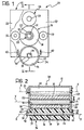
- a device 20 comprises a support casing 21.
- this casing has a substantially inverted U-shape with two facing side walls 22 and 23. Between these walls, in the upper part of the support casing 21, there is mounted a drive roller 24 rotatable about an axis X-X fixed with respect to the casing.
- This drive roller is constituted, at least in its outer parts, by a thermal insulation material, preferably a high hardness elastomeric material.
- a pulley 25 which can be connected to an electric drive motor by means of a belt or chain.
- This heating roller has an essentially tubular form and comprises an inner hub 27 of hard metal, such as nitrided steel, and an outer annular element 28 of material having a high thermal conductivity, preferably aluminium anodised on its outer surface.
- the inner hub 27 of the heating roller 26 is rotatably mounted, substantially without radial play, about a heating device generally indicated 29 and comprising an outer cylindrical cladding 30 of hard metal material, for example nitrided steel fixed about a heater element 31 of type known per se, including within its interior one or more resistors.
- a heating device generally indicated 29 and comprising an outer cylindrical cladding 30 of hard metal material, for example nitrided steel fixed about a heater element 31 of type known per se, including within its interior one or more resistors.
- the inner surface of the hub 27 and the outer surface of the element 30 are lapped for the purpose of reducing the friction between them and ensuring an optimum transmission of heat from the heater element 31 to the outer heat conductive element 28 of the heating roller 26.
- the ends of the heater element 31 are mounted with radial play in corresponding apertures positioned in the side walls 22 and 23 of the support casing 21.
- the heating roller 26, which is rotatably mounted about the heater element 31, is thus rotatable about an axis Y-Y which is movable relative to the support casing 21.
- the heating roller 26 is disposed between a pair of rollers 32 and 33 of thermal insulation material freely rotatably mounted about respective axes which are fixed with respect to the support casing 21.
- a roller pad Beneath the heating roller 26, between the side walls 22 and 23 of the support casing 21, is mounted a roller pad generally indicated 34.
- this roller comprises a shaft 35 on which is fixed a cylindrical layer 36 of thermal insulation material clad by a thin layer 37 of thermally conductive material.
- the thermal insulation layer 36 is constituted for example by a, preferably soft, elastomeric or plastics material.
- the thermally conductive surface layer 37 of the roller pad 34 is constituted for example by a thermally conductive silicone material.
- ends of the shaft 35 of the roller pad 34 extend into corresponding lower slots 38 and 39 of the side walls 22 and 23 of the support casing.
- the diameter of the roller pad 34 is such that it is held in contact with the heating roller 26 without the ends of its shaft 35 engaging the bottom of the associated slots 38 and 39 of the side walls 22 and 23 of the support casing.
- the roller pad 34 is therefore rotatable with respect to the support casing 21 about an axis Z-Z parallel to the axes X-X and Y-Y, this axis Z-Z not however being fixed with respect to the support casing 21.
- the drive roller 24 In operation, when the drive roller 24 is driven to rotate by means of the associated pulley 25, it causes rotation of the heating roller 26 about the heating element 31.
- the heating roller 26 in turn drives the roller pad 34 to rotate. Since the drive roller 24 is (at least superficially) made of thermally insulating material it absorbs almost no heat from the heating roller 26. This latter on the other hand transfers heat to the surface layer 37 of the roller pad 34. This latter can then be applied to an article, with the interposition of a ribbon which, on its face facing the article, carries the image of thermofusible ink, to transfer this image thermally onto the article.
- roller pad 34 To cause application of the roller pad 34 onto an article to achieve the thermal transfer thereto, various arrangements can be adopted.
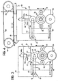
- FIG 3 there is shown an arrangement in which the support casing 21 of the device 20 described above is connected to a supporting structure 50 so as to be movable in an essentially vertical direction with respect thereto.
- the support casing 21 of the device 20 is connected to the supporting structure 50 by means of a pair of articulated arms 43 in such a way as to form an articulated parallelogram.
- the support casing 21 is connected to the rod 44a of a fluid pressure cylinder 44 the body 44b of which is pivotally connected to the supporting structure 50.
- the pulley 25 connected to the drive roll 24 is coupled by means of a belt 45 to a pulley 46 driven to rotate by an electric motor 47 fixed to the supporting structure 50.
- the axes of the pulleys 25 and 47 preferably lie in a plane parallel to. the arms 43.
- FIG 4 there is shown a variant embodiment in which the supporting structure 50 is mounted slidably along one or more guides 51 and is connected to a belt or chain 48 passing over two pulleys 49 one of which, in a manner not illustrated in Figure 4, has a drive motor associated therewith.
- roller pad 34 For a good printing of an image onto an article it is convenient that the speed of rotation of the roller pad 34 is suitably controlled as will be described hereinafter.
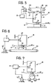
- FIG 5 there is shown a printing station for the thermal transfer of images from a ribbon 4 to an article A, in which the thermal transfer of the image takes place with the ribbon 4 stationary, whilst the article A is stationary.
- the transfer of the image takes place with apparatus of the type previously described with reference to Figure 4.
- an electric motor 52 which, via a control unit 15 is synchronised with the motor 47 which, via the rollers 24 and 26, drives the rotation of the roller pad 34. Synchronisation between the motors 52 and 47 is such that the tangential velocity of the roller pad 34 in the image transfer phase is substantially equal to the speed of advance of the supporting structure of the device.
- Figure 6 there is shown another station for printing an image from a ribbon 4 onto an article A in linear motion on a belt or strip conveyor 53, driven by a motor 52'.
- the printing apparatus of Figure 6 is substantially of the type previously described with reference to Figure 3, with the supporting structure 50 stationary.
- the apparatus of Figure 6 comprises a control unit 15 arranged to synchronise the motors 47 and 52' in such a way that in the thermal transfer phase of an image from the ribbon 4 to the article A the peripheral tangential velocity of the roller pad 34 is substantially equal to the linear velocity of displacement of the article A.
- Figure 7 there is shown a similar apparatus for printing an image from a ribbon 4 to an article A disposed rotatably on a pair of rollers 54 and 55, at least one of which is driven to rotate by a motor 52".
- the apparatus of Figure 7 comprises a device of the type previously described with reference to Figure 3, with the supporting structure 50 stationary.
- the motors 47 and 52" are synchronised by a control unit 15 in such a way that during thermal transfer of an image from the ribbon 4 to the article A the peripheral tangential velocity of the roller pad 34 is substantially equal to the peripheral tangential velocity of the article A.
- the device for the thermal transfer of images according to the invention in the various embodiments described up to now can be utilised in a final station of apparatus for printing onto articles images preliminarily provided on a ribbon according to one of various known methods, for example according to one of the methods known from European patent application EP-A-0 572 999 or according to one of the procedures which will be described hereinafter.
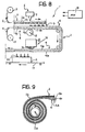
- the reference numeral 1 generally indicates a printing machine for performing a method according to the invention.
- an inked ribbon 2 is unwound from a roll 3 and a receiver ribbon 4 is unwound from a roll 5.
- the inked ribbon 2 comprises a substrate 2a for example of mylar or polyester, on one face of which is applied a thermofusible ink layer 2b.
- the receiver ribbon 4 comprises a substrate 4a, also constituted for example by a film of mylar or polyester, to one face of which is applied a coating or layer 4b of a substantially transparent material.
- the layer 4b is thermofusible at a temperature greater than that of the ink 2b of the inked ribbon 2.
- the material of the layer 4b of the receiver ribbon 4 can be a wax, for example a paraffin wax, or a resin.
- the ribbons 2 and 4 arrive at a first station 6 in which they pass in juxtaposed relation between a thermal print head 7, for example of the dot matrix type, and a counter-roller 8.
- inked layer 2b of the inked ribbon 2 faces the transparent layer 4b of the receiver ribbon 4.
- the thermal print head 7 causes selective transfer of ink 2b from the inked ribbon 2 to the transparent layer 4b of the receiver ribbon 4 in such a way as to form on the receiver ribbon a positive mirror image of the image which it is desired to print onto an article.
- This positive mirror image is indicated 9 in Figure 8.
- the thermal print head 7 is made to operate at a temperature such that it is able to cause selective transfer of ink from the inked ribbon to the receiver ribbon, but lower than the temperature at which the transparent layer 4b separates from the substrate 4a of the receiver ribbon.
- the receiver ribbon 4 is in contact with the counter-roller 8 which "absorbs" a significant quantity of heat maintaining the receiver belt at a lower temperature than that of the inked ribbon 2 which is however in direct contact with the thermal print head 7.
- the receiver ribbon 4 Downstream from the station 6 the receiver ribbon 4 then reaches a further station 10 in which the positive mirror image is thermally transferred onto the surface of an article A carried for example by a conveyor belt 11.
- the station 10 is for example of the type shown in Figure 6.
- the receiver ribbon 4 is now heated by means of a heat transfer device of type previously described, to a temperature such as to cause the transfer onto the surface of the article A both of the image and of a portion 4c of the transparent layer 4b with which the receiver ribbon 4 is coated.
- the contact surface between the ribbon 4 and the article A is relatively rather more extensive than the surface (line of dots) of contact between the head 7 and the ribbon 2 in the station 6.
- there is a transfer of a "mass" of heat to the receiver ribbon 4 which encourages a good transfer onto the article of the image and of part of the transparent coating of the ribbon 4.
- the portion 4c of the transparent material transferred onto the article A provides an effective protection for the image.
- This arrangement allows an easier reloading of new ribbons.
- the transparent layer 4b of the ribbon is thermofusible at a higher temperature of that of the inked layer of the inked ribbon.
- FIGS 10a and 10c there is illustrated an embodiment of the printing machine according to the invention in which real time printing of an image having predetermined characteristics is made possible.
- the positive mirror image is then transferred onto an article A at the station 10, again in the manner previously described with reference to Figure 8.
- the ribbons 2 and 4 are made return, by an amount substantially equal to the distance travelled by the receiver ribbon 4 between the first station 6 and the second station 10, as is shown in Figure 10b, until these ribbons are brought back to the position illustrated in Figure 10c, in which the transfer of ink from ribbon 2 to ribbon 4 commencing from portions of these ribbons utilised for the preceding image print can be recommenced.
Landscapes
- Physics & Mathematics (AREA)
- Optics & Photonics (AREA)
- Electronic Switches (AREA)
- Impression-Transfer Materials And Handling Thereof (AREA)
- Labeling Devices (AREA)
- Rolls And Other Rotary Bodies (AREA)
- Developing Agents For Electrophotography (AREA)
- Printing Methods (AREA)
- Inks, Pencil-Leads, Or Crayons (AREA)
Claims (20)
- Dispositif pour le transfert thermique d'images sur des articles (A), comprenant :caractérisé en ce queune structure support (21),un rouleau chauffant (26) et une garniture de rouleau (34) monté en rotation en contact l'un avec l'autre, etdes moyens moteurs (24, 25, 45 à 47) susceptibles de fonctionner pour provoquer la rotation à la fois du rouleau chauffant (26) et de la garniture de rouleau (34) ;la garniture de rouleau (34) étant prévue pour être appliquée sur un article (A) avec interposition d'un ruban (4) qui, sur la face tournée vers l'article, porte une image en encre thermofusible prévue pour transfert thermique de l'image sur l'article (A) ;
lesdits moyens moteurs comprennent un rouleau d'entraínement (24) motorisé, monté à rotation autour d'un axe (X-X) qui est fixé par rapport à ladite structure (21), en contact avec le rouleau chauffant (26) ;
le rouleau chauffant (26) et la garniture de rouleau (34) étant montés à rotation autour d'axes (Y-Y ; Z-Z) respectifs, déplaçables par rapport à ladite structure (21) ; la garniture de rouleau (34) étant associée à des moyens élastiques (41, 42) visant à le déplacer contre le rouleau chauffant (26) vers le rouleau d'entraínement (24) ; le rouleau chauffant (26) étant associé à des moyens de guidage (32, 33) latéraux susceptibles de fonctionner pour le retenir entre le rouleau d'entraínement (24) et la garniture de rouleau (34). - Dispositif selon la revendication 1, caractérisé en ce que le rouleau d'entraínement (24) est formé au moins sur sa zone radialement la plus à l'extérieur d'un matériau d'isolation thermique, de préférence d'un matériau élastomère.
- Dispositif selon la revendication 1 ou la revendication 2, caractérisé en ce que la garniture de rouleau (34) comprend une partie radialement intérieure (36) en matériau isolant de la chaleur, munie d'un revêtement (37) en matériau conducteur de la chaleur, de préférence en silicone.
- Dispositif selon l'une des revendications précédentes, caractérisé en ce que le rouleau chauffant (26) comprend un corps tubulaire (28) en matériau conducteur de la chaleur, de préférence en aluminium ou en un alliage d'aluminium, monté à rotation autour d'un boítier (30, 31) tubulaire réalisé en matériau conducteur de la chaleur, contenant au moins une résistance de chauffage.
- Dispositif selon l'une quelconque des revendications précédentes, caractérisé en ce que lesdits moyens de guidage comprennent deux rouleaux (32, 33) susceptibles de tourner librement autour d'axes fixés respectifs par rapport à la structure support (21) ; lesdits rouleaux de guidage (32, 33) étant disposés sur des côtés opposés du rouleau chauffant (26).
- Dispositif selon l'une quelconque des revendications précédentes, caractérisé en ce qu'il comprend une structure support (50), à laquelle ladite structure support (21) est connectée de manière à être déplaçable sur une direction prédéterminée, entre lesdits structures (50, 21) étant prévus des moyens actionneurs (44) susceptibles de fonctionner pour provoquer le déplacement de la structure support (21) par rapport à la structure support (50).
- Dispositif selon la revendication 6, caractérisé en ce que la structure support (21) est couplée à la structure support (50) par des moyens de liaison (43) quadrilatéraux articulés.
- Dispositif selon la revendication 6 ou la revendication 7, caractérisé en ce que ledit rouleau d'entraínement (24) est couplé à un moteur (47) fixé sur ladite structure support (50).
- Dispositif selon l'une des revendications précédentes, pour le transfert thermique d'une image sur un article stationnaire (A),
caractérisé en ce que ladite structure support (50, 21) est associée à des deuxièmes moyens moteurs (52) susceptibles de fonctionner pour provoquer un déplacement dans une direction prédéterminée, sensiblement parallèle à la surface de l'article destiné à recevoir l'image ; des moyens de commande (15) étant prévus pour commander lesdits premiers moyens moteurs (47) et lesdits deuxièmes moyens moteurs (52), d'une manière telle que, durant le transfert d'une image, la vitesse tangentielle périphérique de la garniture de rouleau (34) soit sensiblement identique à la vitesse de déplacement de la structure support (50, 21) dans ladite direction. - Dispositif selon l'une quelconque des revendications 1 à 8, pour le transfert d'une image sur un article (A) en déplacement linéaire dans une direction prédéterminée ; caractérisé en ce qu'il comprend des moyens de commande (15) adaptés pour commander lesdits moyens moteurs (47) de manière que, durant le transfert d'une image sur un article (A), la vitesse tangentielle périphérique de la garniture de rouleau (34) soit sensiblement identique à la vitesse de déplacement dudit article (A).
- Dispositif selon l'une quelconque des revendications 1 à 8 pour le transfert d'une image sur un article (A) dans un déplacement rotatif autour d'un axe ;
caractérisé en ce qu'il comprend des moyens de commande (15) susceptibles de fonctionner pour commander lesdits moyens moteurs (47) d'une manière telle que, durant le transfert d'une image sur l'article (A), la vitesse tangentielle périphérique de la garniture de rouleau (A) soit sensiblement identique à la vitesse tangentielle périphérique de l'article (A) . - Utilisation d'un dispositif de transfert thermique selon l'une ou plusieurs des revendications précédentes pour imprimer des images sur un article (A).
- Procédé d'impression d'une image sur un article (A), comprenant
une première phase de transfert thermique sélectif d'une encre thermofusible (2b) depuis un ruban encré (2) flexible, sur une face d'un ruban récepteur (4) flexible, de manière à former sur le ruban récepteur (4) une image positive en miroir (9) d'une image devant être imprimée sur l'article (A), et
une deuxième phase, lors de laquelle l'image positive en miroir (9) est transférée thermiquement du ruban récepteur (4) à l'article (A), à l'aide d'un dispositif selon l'une quelconque des revendications 1 à 11, de manière à former une image souhaitée sur l'article ;
le ruban récepteur (4) ayant un revêtement ou couche (4b) en un matériau sensiblement transparent sur la face prévue pour recevoir l'image positive en miroir (9) ;
l'image positive en miroir (9) étant transférée sur ledit revêtement ou couche (4b) du ruban récepteur lors de la première phase (44) ;
l'image et une partie (4c) dudit revêtement ou couche (4b) du ruban récepteur (4), qui couvre ladite image, étant, les deux, transférés à l'article (A) lors de la deuxième phase. - Procédé selon la revendication 13, caractérisé en ce que le revêtement ou couche (4b) du ruban récepteur (4) est thermofusible à une température plus élevée que celle de l'encre (2b) du ruban encré (2).
- Procédé selon la revendication 13 ou 14, dans lequel le ruban encré (2) comprend un substrat support (2a) sur lequel est appliqué une couche d'encre (2b) avec interposition d'une couche d'un premier agent de détachement et dans laquelle le ruban récepteur (4) comprend un substrat (4a) sur lequel ledit revêtement ou couche (4b) sensiblement transparent est appliqué avec interposition d'une couche du deuxième agent de détachement ;
caractérisé en ce que les couches d'agents de détachement situées sur le ruban encré (2) et le ruban récepteur (4) sont formées de manière que, lors de la première phase, le ruban encré (2) puisse fournir de l'encre au ruban récepteur (4) et que, lors de la deuxième phase, le ruban récepteur (4) puisse fournir à l'article (A) l'encre (9) ayant été reçue, lors de la première phase et une partie dudit revêtement ou couche (4b) sensiblement transparent. - Procédé selon l'une quelconque des revendications 13 à 15, caractérisé en ce que le ruban encré (2) et le ruban récepteur (4) sont déroulés depuis une bobine unique sur laquelle ils ont été préalablement enroulés en un état juxtaposé.
- Procédé selon l'une quelconque des revendications 13 à 15, caractérisé en ce que le ruban encré (2) et le ruban récepteur (4) sont déroulés depuis des rouleaux ou bobines (3, 5) séparés.
- Procédé selon l'une quelconque des revendications 13 à 17, dans lequel, pour imprimer une image en temps réel, l'image en miroir (9) positive est formée, lors de la première phase, sur le ruban récepteur (4) en un premier poste (6), puis au moins le ruban encré (2) est avancé tandis que le premier poste (6) est désactivé, afin de transférer le ruban récepteur (4) à un deuxième poste (10) auquel ladite deuxième phase est exécutée ; après que ladite deuxième ait été exécutée, le ruban récepteur (4) est rétracté d'une distance sensiblement égale à la distance antérieurement parcourue depuis ledit premier audit deuxième poste (6 ; 10) afin de permettre le transfert subséquent de l'encre depuis le ruban encré (2) au ruban récepteur (4) au premier poste (6), en commençant pratiquement depuis des parties de tels rubans immédiatement en amont des parties utilisées pour l'impression de l'image précédente.
- Dispositif d'impression pour exécuter le procédé selon une ou plusieurs des revendications 13 à 18, comprenant un premier poste (6) susceptible de fonctionner pour exécuter un transfert thermique sélectif d'encre thermofusible (2b) depuis un ruban encré (2) flexible à une face d'un ruban récepteur (4) flexible, d'une manière permettant de former sur le ruban récepteur (4) une image en miroir (9) positive de l'image à imprimer sur un article (A), et un deuxième poste (9) susceptible de fonctionner pour effectuer le transfert thermique de l'image en miroir (9) positive du ruban récepteur (4) à l'article (A), de manière à former l'image souhaitée sur lui ; la machine étant caractérisée par le fait que le deuxième poste (10) comprend un dispositif selon une ou plusieurs des revendications 1 à 11, est en mesure d'appliquer au ruban récepteur (4) une température plus élevée que celle appliquée au ruban encré (2) dans le premier poste (6), de manière que l'image et une partie (4c) dudit revêtement ou couche (4b) du ruban récepteur (4) soient, les deux, transférées à l'article (A).
- Dispositif selon la revendication 19, pour la mise en oeuvre du procédé selon la revendication 18, caractérisé en ce qu'il comprend des moyens (15) utilisables pour provoquer l'inversion du déplacement du ruban encré (2) et du ruban récepteur (4).
Applications Claiming Priority (2)
| Application Number | Priority Date | Filing Date | Title |
|---|---|---|---|
| IT96TO001098A IT1289818B1 (it) | 1996-12-30 | 1996-12-30 | Procedimento, apparecchiatura e materiali per la stampa di un'immagine su un articolo. |
| ITTO961098 | 1996-12-30 |
Publications (3)
| Publication Number | Publication Date |
|---|---|
| EP0856416A2 EP0856416A2 (fr) | 1998-08-05 |
| EP0856416A3 EP0856416A3 (fr) | 1998-10-07 |
| EP0856416B1 true EP0856416B1 (fr) | 2003-03-12 |
Family
ID=11415169
Family Applications (1)
| Application Number | Title | Priority Date | Filing Date |
|---|---|---|---|
| EP97122847A Expired - Lifetime EP0856416B1 (fr) | 1996-12-30 | 1997-12-24 | Appareil, méthode et équipement pour transférer une image sur un article par transfert thermique |
Country Status (4)
| Country | Link |
|---|---|
| EP (1) | EP0856416B1 (fr) |
| DE (1) | DE69719718T2 (fr) |
| ES (1) | ES2193322T3 (fr) |
| IT (1) | IT1289818B1 (fr) |
Families Citing this family (1)
| Publication number | Priority date | Publication date | Assignee | Title |
|---|---|---|---|---|
| IT201600081050A1 (it) * | 2016-08-02 | 2018-02-02 | Eidos S R L | Macchina per la stampa di immagini su articoli mediante un rullo a trasferimento termico. |
Family Cites Families (10)
| Publication number | Priority date | Publication date | Assignee | Title |
|---|---|---|---|---|
| JPS59214666A (ja) * | 1983-05-19 | 1984-12-04 | Mitani Denshi Kogyo Kk | 熱転写記録装置 |
| US5264279A (en) * | 1989-09-19 | 1993-11-23 | Dai Nippon Insatsu Kabushiki Kaisha | Composite thermal transfer sheet |
| JPH0577556A (ja) * | 1991-09-18 | 1993-03-30 | Matsushita Electric Ind Co Ltd | 熱転写記録方法、中間媒体及び転写体 |
| US5532724A (en) * | 1992-08-31 | 1996-07-02 | Toppan Printing Co., Ltd. | Image transfer device |
| US5372985A (en) * | 1993-02-09 | 1994-12-13 | Minnesota Mining And Manufacturing Company | Thermal transfer systems having delaminating coatings |
| JPH06255080A (ja) * | 1993-03-04 | 1994-09-13 | Fuji Photo Film Co Ltd | 押圧用ローラ及び挟持搬送ローラ装置 |
| JPH07146627A (ja) * | 1993-11-13 | 1995-06-06 | Asahi Optical Co Ltd | 連続紙を用いるプリンタ |
| JPH07227956A (ja) * | 1994-02-22 | 1995-08-29 | Toppan Printing Co Ltd | 熱転写式カードプリンタの印圧緊急解除装置 |
| JPH07276709A (ja) * | 1994-04-05 | 1995-10-24 | Michiharu Todo | 印刷機 |
| JPH08278669A (ja) * | 1995-04-05 | 1996-10-22 | Tec Corp | 画像形成装置 |
-
1996
- 1996-12-30 IT IT96TO001098A patent/IT1289818B1/it active IP Right Grant
-
1997
- 1997-12-24 DE DE69719718T patent/DE69719718T2/de not_active Expired - Fee Related
- 1997-12-24 EP EP97122847A patent/EP0856416B1/fr not_active Expired - Lifetime
- 1997-12-24 ES ES97122847T patent/ES2193322T3/es not_active Expired - Lifetime
Also Published As
| Publication number | Publication date |
|---|---|
| ES2193322T3 (es) | 2003-11-01 |
| IT1289818B1 (it) | 1998-10-16 |
| DE69719718T2 (de) | 2004-02-05 |
| EP0856416A2 (fr) | 1998-08-05 |
| EP0856416A3 (fr) | 1998-10-07 |
| ITTO961098A1 (it) | 1998-06-30 |
| DE69719718D1 (de) | 2003-04-17 |
Similar Documents
| Publication | Publication Date | Title |
|---|---|---|
| KR100294379B1 (ko) | 열전사인쇄방법및장치 | |
| EP0098033B1 (fr) | Dispositif d'impression thermique par transfert d'encre | |
| JP3428386B2 (ja) | 転写画像形成装置 | |
| GB2089734A (en) | Printing apparatus | |
| EP1363778B1 (fr) | Procede et dispositif pour imprimante a cylindre directe | |
| US4340438A (en) | Roll leaf coating method | |
| US5761597A (en) | Fusing apparatus for a printer | |
| EP1044111A1 (fr) | Procede et appareil de fusion thermique | |
| EP0856416A2 (fr) | Appareil, méthode et équipement pour transférer une image sur un article par transfert thermique | |
| EP0572999B1 (fr) | Procédé et équipement pour imprimer une image sur un article | |
| JP3123554B2 (ja) | リボンカセット | |
| US5583555A (en) | Equipment for printing an image on an article | |
| EP0376170B1 (fr) | Méthode et dispositif d'impression thermique pour grandes surfaces | |
| JPH09156144A (ja) | ライン・サーマルヘッド・プリンタ装置 | |
| JP3200233B2 (ja) | 記録装置 | |
| EP0566161B1 (fr) | Méthode et dispositif d'impression thermique pour grandes surfaces | |
| JPH03232655A (ja) | プリンタ | |
| JPH0325969Y2 (fr) | ||
| JP3483404B2 (ja) | サーマルプリンタ | |
| JPS62146688A (ja) | 転写記録方法 | |
| JPH0365371A (ja) | 熱転写記録媒体への検知用マーク形成方法 | |
| JPH0775915B2 (ja) | 感熱転写記録媒体用検知マーク作製装置 | |
| JPH049171Y2 (fr) | ||
| JPS63205250A (ja) | 感熱転写記録方法及びその装置 | |
| JPS6283156A (ja) | シリアル型熱転写記録装置 |
Legal Events
| Date | Code | Title | Description |
|---|---|---|---|
| PUAI | Public reference made under article 153(3) epc to a published international application that has entered the european phase |
Free format text: ORIGINAL CODE: 0009012 |
|
| AK | Designated contracting states |
Kind code of ref document: A2 Designated state(s): DE ES FR GB |
|
| AX | Request for extension of the european patent |
Free format text: AL;LT;LV;MK;RO;SI |
|
| PUAL | Search report despatched |
Free format text: ORIGINAL CODE: 0009013 |
|
| AK | Designated contracting states |
Kind code of ref document: A3 Designated state(s): AT BE CH DE DK ES FI FR GB GR IE IT LI LU MC NL PT SE |
|
| 17P | Request for examination filed |
Effective date: 19990325 |
|
| AKX | Designation fees paid |
Free format text: AT BE CH DE LI |
|
| RBV | Designated contracting states (corrected) |
Designated state(s): DE ES FR GB |
|
| 17Q | First examination report despatched |
Effective date: 20000803 |
|
| GRAG | Despatch of communication of intention to grant |
Free format text: ORIGINAL CODE: EPIDOS AGRA |
|
| GRAG | Despatch of communication of intention to grant |
Free format text: ORIGINAL CODE: EPIDOS AGRA |
|
| GRAH | Despatch of communication of intention to grant a patent |
Free format text: ORIGINAL CODE: EPIDOS IGRA |
|
| GRAH | Despatch of communication of intention to grant a patent |
Free format text: ORIGINAL CODE: EPIDOS IGRA |
|
| GRAA | (expected) grant |
Free format text: ORIGINAL CODE: 0009210 |
|
| AK | Designated contracting states |
Designated state(s): DE ES FR GB |
|
| REG | Reference to a national code |
Ref country code: GB Ref legal event code: FG4D |
|
| REF | Corresponds to: |
Ref document number: 69719718 Country of ref document: DE Date of ref document: 20030417 Kind code of ref document: P |
|
| ET | Fr: translation filed | ||
| REG | Reference to a national code |
Ref country code: ES Ref legal event code: FG2A Ref document number: 2193322 Country of ref document: ES Kind code of ref document: T3 |
|
| PLBE | No opposition filed within time limit |
Free format text: ORIGINAL CODE: 0009261 |
|
| STAA | Information on the status of an ep patent application or granted ep patent |
Free format text: STATUS: NO OPPOSITION FILED WITHIN TIME LIMIT |
|
| 26N | No opposition filed |
Effective date: 20031215 |
|
| PGFP | Annual fee paid to national office [announced via postgrant information from national office to epo] |
Ref country code: ES Payment date: 20061102 Year of fee payment: 10 |
|
| PGFP | Annual fee paid to national office [announced via postgrant information from national office to epo] |
Ref country code: GB Payment date: 20061114 Year of fee payment: 10 |
|
| PGFP | Annual fee paid to national office [announced via postgrant information from national office to epo] |
Ref country code: DE Payment date: 20061124 Year of fee payment: 10 |
|
| PGFP | Annual fee paid to national office [announced via postgrant information from national office to epo] |
Ref country code: FR Payment date: 20061229 Year of fee payment: 10 |
|
| GBPC | Gb: european patent ceased through non-payment of renewal fee |
Effective date: 20071224 |
|
| PG25 | Lapsed in a contracting state [announced via postgrant information from national office to epo] |
Ref country code: DE Free format text: LAPSE BECAUSE OF NON-PAYMENT OF DUE FEES Effective date: 20080701 |
|
| REG | Reference to a national code |
Ref country code: FR Ref legal event code: ST Effective date: 20081020 |
|
| PG25 | Lapsed in a contracting state [announced via postgrant information from national office to epo] |
Ref country code: GB Free format text: LAPSE BECAUSE OF NON-PAYMENT OF DUE FEES Effective date: 20071224 |
|
| REG | Reference to a national code |
Ref country code: ES Ref legal event code: FD2A Effective date: 20071226 |
|
| PG25 | Lapsed in a contracting state [announced via postgrant information from national office to epo] |
Ref country code: FR Free format text: LAPSE BECAUSE OF NON-PAYMENT OF DUE FEES Effective date: 20071231 Ref country code: ES Free format text: LAPSE BECAUSE OF NON-PAYMENT OF DUE FEES Effective date: 20071226 |