EP0856730A2 - Dispositif compact pour déterminer la consistance d'agglomérés alimentaires - Google Patents
Dispositif compact pour déterminer la consistance d'agglomérés alimentaires Download PDFInfo
- Publication number
- EP0856730A2 EP0856730A2 EP98300032A EP98300032A EP0856730A2 EP 0856730 A2 EP0856730 A2 EP 0856730A2 EP 98300032 A EP98300032 A EP 98300032A EP 98300032 A EP98300032 A EP 98300032A EP 0856730 A2 EP0856730 A2 EP 0856730A2
- Authority
- EP
- European Patent Office
- Prior art keywords
- tester
- hopper
- filter
- pellets
- tester according
- Prior art date
- Legal status (The legal status is an assumption and is not a legal conclusion. Google has not performed a legal analysis and makes no representation as to the accuracy of the status listed.)
- Ceased
Links
Images


Classifications
-
- G—PHYSICS
- G01—MEASURING; TESTING
- G01N—INVESTIGATING OR ANALYSING MATERIALS BY DETERMINING THEIR CHEMICAL OR PHYSICAL PROPERTIES
- G01N3/00—Investigating strength properties of solid materials by application of mechanical stress
- G01N3/56—Investigating resistance to wear or abrasion
- G01N3/565—Investigating resistance to wear or abrasion of granular or particulate material
-
- G—PHYSICS
- G01—MEASURING; TESTING
- G01N—INVESTIGATING OR ANALYSING MATERIALS BY DETERMINING THEIR CHEMICAL OR PHYSICAL PROPERTIES
- G01N33/00—Investigating or analysing materials by specific methods not covered by groups G01N1/00 - G01N31/00
- G01N33/0077—Testing material properties on individual granules or tablets
-
- G—PHYSICS
- G01—MEASURING; TESTING
- G01N—INVESTIGATING OR ANALYSING MATERIALS BY DETERMINING THEIR CHEMICAL OR PHYSICAL PROPERTIES
- G01N2203/00—Investigating strength properties of solid materials by application of mechanical stress
- G01N2203/02—Details not specific for a particular testing method
- G01N2203/026—Specifications of the specimen
- G01N2203/0284—Bulk material, e.g. powders
-
- G—PHYSICS
- G01—MEASURING; TESTING
- G01N—INVESTIGATING OR ANALYSING MATERIALS BY DETERMINING THEIR CHEMICAL OR PHYSICAL PROPERTIES
- G01N33/00—Investigating or analysing materials by specific methods not covered by groups G01N1/00 - G01N31/00
- G01N33/02—Food
Definitions
- the present invention relates to devices for measuring the durability of feed pellets.
- the feed is formed into pellets.
- These pellets are typically anything from a couple of millimetres up to 20 millimetres in diameter.
- EP-B-0,085,507 describes an apparatus in which pellets are repeatedly fed through a section of tubing to simulate the treatment which would occur during transportation from the feed mill to the end user.
- GB-B-2,181,559 describes an alternative feed pellet durability testing apparatus in which the feed pellets are dropped into a hopper having perforated sides and a jet of air is blasted upwards from the bottom of the hopper to agitate the pellets. Any pieces which break off pass through the perforated sides of the hopper and pass out at the bottom of the machine carried along with the airflow.
- Both the above described devices are designed for use on a production line, for continuous testing of the quality of the feed pellets being produced.
- these devices are large and bulky and are thus not easily moved for testing pellets in a different location. This means that if testing of the pellets is to be carried out in more than one location within the factory or outside of the factory (eg. at a distribution centre or at the receiving farm), it is necessary to have dedicated testers at each location.
- a pellet durability tester comprising:
- the tester preferably includes a blow fan timer which, when activated, operates the blower for a preset period of time. This provides a standardised testing period. This preset period of time is preferably 30 seconds.
- the hopper is preferably hinged at one side of the tester to allow it to pivot out of the body of the tester to tip the contents of the hopper into another container for weighing.
- the lid is also preferably hinged to the body of the tester so that it can be pivoted away from the top of the hopper to allow the hopper to be emptied.
- the lid preferably incorporates a filter comprising on air permeable filter pad or sheet to allow air to escape through to the lid.
- the tester is preferably provided with a hood positioned over the filter.
- the hood is preferably hingedly attached to the body of the tester to allow it to be pivoted away from the top of the filter, to allow the filter and hopper to be moved.
- the hood is preferably provided in the form of a truncated pyramid or cone such that when the hopper is pivoted through 180° it forms a funnel portion into which the hopper can be tipped to provide easier collection of the tested pellets.
- the lid may also be pivotably attached to the upper edge of the tester, preferably on a different side to the hopper and the hood.
- the provision of the lid over the top of the hopper allows the tester to be used in any environment, as the filter prevents any of the fines escaping from the tester. This is important where the tester is being used in an environment where the production of large amounts of dust would be unacceptable, such as in an office. Furthermore, with increasingly stricter regulations on dust emissions being introduced, it is important that the tester produces only a minimal amount of dust pollution.
- Locating the filter at the top of the tester means that fewer fines get caught in the filter, increasing the amount of time between filter replacement and/or cleaning.
- the filter is preferably supported above and below by a rigid support.
- This support may be in the form of a perforated plate, cross-members or the like, so as to support the filter without unnecessary impeding the air flow.
- the lower filter support may be provided on the top of the hopper. In order to allow the pellets to be inserted and removed, some or all of such a filter support may be hinged on the hopper, so as to provide an opening flap.
- the filter may include a shield portion comprised of a thin solid disc, a few (approximately 5) centimetres in diameter in the centre of its underside.
- the shield portion which is preferably impervious to air, covers part of the filter above the nozzle.
- the disc deflects pellets and fines projected upward by the air jet, preventing the fines being lodged in the filter. The action of the pellets hitting the disc and the rest of the filter causes vibration in the filter, dislodging any fines which may be lodged in the filter.
- the filter may be used several times before being replaced. Alternatively, the filter may be discarded and replaced after each test. By using a new filter every time a test is conducted, the starting conditions are always the same and thus greater continuity between tests can be achieved.
- the large upper area and overall volume of the hopper allows testing of all sizes of pellets currently available without the need to switch to different hoppers.
- the power supply to the motor is preferably stabilized. By providing voltage stabilising circuitry in the tester itself, the motor always operates at the same speed. This helps to avoid variations in conditions from one test to the next irrespective of the quality of electrical supply to the tester.
- the speed of the blower motor may however be adjustable to compensate for variations in speed of the motor, and hence the pressure and velocity of the air jet, with time, eg. due to aging of the motor and/or clogging of the filter.
- the tester may also be provided with a pressure transducer to monitor the pressure in the testing chamber, to aid in the above mentioned calibration and also to monitor the increase in pressure with time as a result of back-pressure due to clogging of the filter.
- the compact construction of the tester allows it to be carried around whilst still being capable of testing a large range of pellet sizes.
- the tester 1 is provided in a housing which is divided into two parts, a pumping chamber 10 and a testing chamber 11.
- the pumping chamber 10 contains a motorised blower unit 7 for pressurizing the testing chamber 11.
- the pumping chamber is connected to the testing chamber via a nozzle 5 which converts the pressure head inside the pumping chamber into a velocity head.
- the testing chamber 11 has an open top into which is inserted a hopper 2.
- the hopper has a generally conical or pyramidal shape with a rim 16 at the larger end.
- the rim 16 rests on the upper edge 17 of the body of the tester 1 with the body of the hopper 2 contained within the testing chamber 11.
- the hopper is hinged at one edge to the edge of the tester body so that it can be swung out of the body.
- the sides of the hopper are perforated to allow fines to pass into the fine collecting chamber 18.
- the bottom 8 of the hopper is provided with a flat portion which is perforated and which sits in abutment with the nozzle opening. Alternatively the bottom 8 of the hopper may be provided with a hole which is covered by a fine mesh.
- a filter 3 is provided over the hopper to define a tumbling chamber 12 between the hopper and the filter.
- the filter 3 comprises a substantially flat rigid body with a sheet or pad of filter material such as foam provided therein.
- the filter is also hinged to the body of the tester, on the opposite side of the hopper, so that the filter can be swung out of the way of the hopper (see Figure 3).
- the filter sheet or pad is supported from above and below by a rigid perforated plate 27.
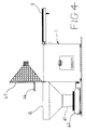
- the lower filter support 43, 44 is provided on the top of the hopper (see Fig. 4). This reduced the number of surfaces which need to be sealed by the filter frame and this minimises the possibility of leaks which can alter the pressure and hence accuracy of the device.
- the filter support comprises a flapped portion 44 which can be hinged open to allow the pellets to be inserted and removed from the hopper.
- a rigid disc 21 of approximately 5cm diameter.
- the disc 21 shields the portion of the filter directly above the nozzle 5 from the air jet. This prevents fines being blasted into the mesh of the filter pad and becoming lodged there, or rupturing the filter sheet where used.
- Rubber strips or the like are provided between the filter and the tester body or between the filter and the hopper and between the hopper and the tester body to form a seal.
- the testing chamber is sealed except for the inlet nozzle and the outlet through the filter.
- the walls of the hopper divide the testing chamber 11 into two regions: the tumbling chamber 12, is provided above the hopper; and the fine collection chamber 18 provided below the hopper.
- a hood 4 Hingedly attached to the upper part of the testing chamber 11 is a hood 4.
- the hood 4 has the shape of a truncated cone or pyramid with a hole 9 provided at the upper part.
- This hole 9 provides two functions. During the tumbling phase of operation, the air from the nozzle passes into the tumbling chamber 12 and through the filter 3 into the volume 14 contained within the hood. The hole therefore provides an exit vent or chimney through which the air can escape.
- the second function of the hole is that once tumbling is complete and the pellets are being removed from the hopper, the hood is pivoted through 180° as shown in Figure 3 such that the hole 9 is now facing downwards.
- the hopper and its contents 6 can be similarly pivoted about the same axis such that the upper portion of the hopper comes to rest on top of the hood portion, tipping the tested pellets 6 into the hood 4, such that they are funnelled out of the hole 9 in the hood into a collection container 41 provided below.
- the user In order to test a sample of pellets 6, the user initially weighs the pellets to establish their starting weight. The hood 4 and filter 3 are then pivoted through 180°, in opposite senses, to expose the hopper. The pellets are then tipped into the hopper and the filter is returned to its position over the top of the hopper. The hood is then similarly returned to its position over the top of the filter and locked down, by locks 20, in position. The user then presses the start button 15 to initiate the test sequence. The blower forces air from the blower chamber into the nozzle, providing a high velocity jet of air directed vertically upward into the pile of test pellets 6 lying at the bottom of the hopper.
- the pellets then slip down the sides of the hopper back to the bottom again and into the air stream where they are again thrown upwards in the air jet.
- This repeated cascading of the pellets in the chamber results in repeated collisions between the pellets and the walls of the tumbling chamber causing small parts of the pellets, called fines 19, to break off.
- the perforations provided in the sides of the hopper allow the fines to drop through into the fine collecting chamber 18 of the testing chamber 11.
- the pressure within increases, causing a flow of air through the filter pad into the hollow part of the hood and out through the chimney at the top.
- the filter pad prevents any fines from passing out of the tester. Any fines in the tumbling chamber will ultimately fall through the hopper perforations and collect in the fine collection chamber. The fines can then be emptied at a later time through the door 13 provided on the side of the tester.
- the door 13 is substantially air-tight to prevent air escaping during testing.
- the controller for the tester will turn off the blower after a predetermined test period. It is important to have a fixed test period to ensure consistency of test results. Typically a test period of about 30 seconds is satisfactory to provide appropriate test results. However, there may be reasons for having an extended test period, for example, if the pellets are particularly durable and require a considerable amount of tumbling before an appreciable amount of material breaks off. Such extended test periods can be simply provided by running the tester for two or more normal (30s) test periods. In order to maintain continuity of test results throughout the life of the tester, calibration can be carried out periodically. As the blower motor 28 ages, it may change its speed and efficiency characteristics. To counter this the tester may be provided with means to carry out small adjustments to the speed of the motor.
- a pressure sensor 25 is provided in the testing chamber 11. This measures the pressure in the chamber 11 to allow calibration of the blower to a set pressure. This sensor can also be used to monitor an increase in pressure due to the build up of filtered material in the filter. By monitoring this pressure, it can be ascertained when it is necessary to clean or replace the filter.
- the user releases and opens the hood.
- the filter is also then pivoted out of position and finally the hopper is pivoted out of the body of the tester so that the remaining pellets are tipped into the hood.
- the pellets drop into the hood and run down the angled sides and out of the bottom of the hole 9. They are then collected in a collection container 41 and reweighed. Alternatively, they may be tipped directly onto the weighing device 42.
- the end weight of the pellets provides an indication of the durability of the pellets. The user normally starts with 100 grams of pellets prior to testing.
- the end weight provides an indication of the durability, or a durability value, eg. 92.
- the dimensions of the hopper opening at the top of the tester is about 280 mm x 280 mm which allows the full range of feed pellets to be accommodated in the hopper whilst providing a tester of a manageable size about 380mm(l) x 280mm(w) x 430mm(h).
Landscapes
- Chemical & Material Sciences (AREA)
- Health & Medical Sciences (AREA)
- Life Sciences & Earth Sciences (AREA)
- General Health & Medical Sciences (AREA)
- Analytical Chemistry (AREA)
- Biochemistry (AREA)
- Physics & Mathematics (AREA)
- General Physics & Mathematics (AREA)
- Immunology (AREA)
- Pathology (AREA)
- Engineering & Computer Science (AREA)
- Food Science & Technology (AREA)
- Medicinal Chemistry (AREA)
- Sampling And Sample Adjustment (AREA)
- Feeding And Watering For Cattle Raising And Animal Husbandry (AREA)
Applications Claiming Priority (2)
| Application Number | Priority Date | Filing Date | Title |
|---|---|---|---|
| GB9700180A GB2320963A (en) | 1997-01-07 | 1997-01-07 | Feed pellet durability tester |
| GB9700180 | 1997-01-07 |
Publications (2)
| Publication Number | Publication Date |
|---|---|
| EP0856730A2 true EP0856730A2 (fr) | 1998-08-05 |
| EP0856730A3 EP0856730A3 (fr) | 1999-04-21 |
Family
ID=10805600
Family Applications (1)
| Application Number | Title | Priority Date | Filing Date |
|---|---|---|---|
| EP98300032A Ceased EP0856730A3 (fr) | 1997-01-07 | 1998-01-06 | Dispositif compact pour déterminer la consistance d'agglomérés alimentaires |
Country Status (4)
| Country | Link |
|---|---|
| US (1) | US5962793A (fr) |
| EP (1) | EP0856730A3 (fr) |
| CA (1) | CA2226326A1 (fr) |
| GB (1) | GB2320963A (fr) |
Families Citing this family (3)
| Publication number | Priority date | Publication date | Assignee | Title |
|---|---|---|---|---|
| US20070014642A1 (en) * | 2005-02-02 | 2007-01-18 | Cristian Teodorescu | Automatic seeds or pellets feeder |
| GB2449700A (en) * | 2007-06-01 | 2008-12-03 | Uni For Miljoe Og Biovitenskap | Determining the Durability of Animal Feed Pellets |
| NO328834B1 (no) * | 2008-09-12 | 2010-05-25 | Fras Technology As | Fluidanalysesystem og metode for drift av et analysesystem |
Family Cites Families (9)
| Publication number | Priority date | Publication date | Assignee | Title |
|---|---|---|---|---|
| DE1066550B (de) * | 1954-12-01 | 1959-10-08 | Esso Research And Engineering Company, Elizabeth, N. J. (V. St. A.) | Verfahren zur Herstellung abriebfester, aus »/-Tonerde bestehender Katalysatorträger |
| GB1343963A (en) * | 1971-11-17 | 1974-01-16 | Procter & Gamble Ltd | Method and apparatus for measuring dust properties of granular materials |
| US3766776A (en) * | 1972-03-31 | 1973-10-23 | Central Soya Co | Method for determining the durability of pellets and apparatus therefor |
| US4143539A (en) * | 1976-02-23 | 1979-03-13 | Atlantic Richfield Company | Apparatus and method for determining the attrition properties of a mass of solid particles |
| DE3368766D1 (en) * | 1982-01-28 | 1987-02-05 | Holmen Chemicals | Pellet durability tester |
| US4582254A (en) * | 1984-06-06 | 1986-04-15 | Eutectic Corporation | Device for the controlled multiple feeding of powder material |
| GB2181559B (en) * | 1985-08-29 | 1989-08-09 | Holmen Chemicals | Pellet durability tester |
| JPH0650761Y2 (ja) * | 1990-09-13 | 1994-12-21 | 日本アルミニウム工業株式会社 | 粉粒体検査装置 |
| DK172867B1 (da) * | 1993-01-22 | 1999-08-23 | Norvidan Overseas As | Fremgangsmåde og måleapparat til kontrol af især foderpiller |
-
1997
- 1997-01-07 GB GB9700180A patent/GB2320963A/en not_active Withdrawn
-
1998
- 1998-01-06 US US09/003,146 patent/US5962793A/en not_active Expired - Fee Related
- 1998-01-06 EP EP98300032A patent/EP0856730A3/fr not_active Ceased
- 1998-01-06 CA CA002226326A patent/CA2226326A1/fr not_active Abandoned
Also Published As
| Publication number | Publication date |
|---|---|
| GB9700180D0 (en) | 1997-02-26 |
| EP0856730A3 (fr) | 1999-04-21 |
| GB2320963A (en) | 1998-07-08 |
| US5962793A (en) | 1999-10-05 |
| CA2226326A1 (fr) | 1998-07-07 |
Similar Documents
| Publication | Publication Date | Title |
|---|---|---|
| JPH02275340A (ja) | 梱入りタバコの葉柄含量を測定するための方法及び装置 | |
| JPH0272020A (ja) | 粉体供給装置 | |
| US5962793A (en) | Compact feed pellet durability tester | |
| GB2235884A (en) | Sieve analysis apparatus | |
| JP2009521370A (ja) | 管を充填するために用いられる任意の充填システムに対する触媒および/または微粒子の自動供給の提供 | |
| JPH09113435A (ja) | バグフィルターの粉塵保持量の測定装置 | |
| JPS62259018A (ja) | 見掛比重測定用計重装置 | |
| KR100932153B1 (ko) | 사이로장치 | |
| EP0608196B1 (fr) | Méthode et appareil de mesure pour tester notamment des pellets de fourage | |
| JP3768341B2 (ja) | 米穀用の計量袋詰め機 | |
| JP3845812B2 (ja) | 穀類選別計量機 | |
| JP4302797B2 (ja) | 籾摺計量装置 | |
| KR100898808B1 (ko) | 사이로장치 | |
| JPH07113680A (ja) | 粉体供給装置 | |
| JP3153674B2 (ja) | 籾あるいは麦の自主検定方法およびその装置 | |
| SU1521367A1 (ru) | Измельчитель грубых кормов | |
| CN220391707U (zh) | 一种玉米全自动包装秤 | |
| CN221908157U (zh) | 一种食品检验检测农药残留物筛选装置 | |
| JP4197793B2 (ja) | 生コンクリート製造装置 | |
| CN117049201B (zh) | 一种给煤机出口防积煤装置 | |
| JPH0699091A (ja) | 米糠等の粉体捕集装置 | |
| JP3458191B2 (ja) | 含水率計内蔵型自動選別計量機 | |
| JPS6353867B2 (fr) | ||
| JPH0776392A (ja) | 粉体ホッパー補助装置 | |
| JPH06301041A (ja) | 微粒子の散布装置および散布方法 |
Legal Events
| Date | Code | Title | Description |
|---|---|---|---|
| PUAI | Public reference made under article 153(3) epc to a published international application that has entered the european phase |
Free format text: ORIGINAL CODE: 0009012 |
|
| AK | Designated contracting states |
Kind code of ref document: A2 Designated state(s): BE DE DK ES FR GB IE IT NL SE |
|
| AX | Request for extension of the european patent |
Free format text: AL;LT;LV;MK;RO;SI |
|
| PUAL | Search report despatched |
Free format text: ORIGINAL CODE: 0009013 |
|
| AK | Designated contracting states |
Kind code of ref document: A3 Designated state(s): AT BE CH DE DK ES FI FR GB GR IE IT LI LU MC NL PT SE |
|
| AX | Request for extension of the european patent |
Free format text: AL;LT;LV;MK;RO;SI |
|
| 17P | Request for examination filed |
Effective date: 19990927 |
|
| AKX | Designation fees paid |
Free format text: DE DK ES FR GB NL |
|
| RBV | Designated contracting states (corrected) |
Designated state(s): BE DE DK ES FR GB IE IT NL SE |
|
| 17Q | First examination report despatched |
Effective date: 20010124 |
|
| GRAG | Despatch of communication of intention to grant |
Free format text: ORIGINAL CODE: EPIDOS AGRA |
|
| STAA | Information on the status of an ep patent application or granted ep patent |
Free format text: STATUS: THE APPLICATION HAS BEEN REFUSED |
|
| 18R | Application refused |
Effective date: 20011228 |