EP0856865A2 - Relais électromagnétique - Google Patents
Relais électromagnétique Download PDFInfo
- Publication number
- EP0856865A2 EP0856865A2 EP98101751A EP98101751A EP0856865A2 EP 0856865 A2 EP0856865 A2 EP 0856865A2 EP 98101751 A EP98101751 A EP 98101751A EP 98101751 A EP98101751 A EP 98101751A EP 0856865 A2 EP0856865 A2 EP 0856865A2
- Authority
- EP
- European Patent Office
- Prior art keywords
- retainer
- movable
- iron member
- electromagnetic relay
- contact element
- Prior art date
- Legal status (The legal status is an assumption and is not a legal conclusion. Google has not performed a legal analysis and makes no representation as to the accuracy of the status listed.)
- Granted
Links
Images


Classifications
-
- H—ELECTRICITY
- H01—ELECTRIC ELEMENTS
- H01H—ELECTRIC SWITCHES; RELAYS; SELECTORS; EMERGENCY PROTECTIVE DEVICES
- H01H50/00—Details of electromagnetic relays
- H01H50/54—Contact arrangements
- H01H50/60—Contact arrangements moving contact being rigidly combined with movable part of magnetic circuit
-
- H—ELECTRICITY
- H01—ELECTRIC ELEMENTS
- H01H—ELECTRIC SWITCHES; RELAYS; SELECTORS; EMERGENCY PROTECTIVE DEVICES
- H01H1/00—Contacts
- H01H1/58—Electric connections to or between contacts; Terminals
- H01H1/5822—Flexible connections between movable contact and terminal
-
- H—ELECTRICITY
- H01—ELECTRIC ELEMENTS
- H01H—ELECTRIC SWITCHES; RELAYS; SELECTORS; EMERGENCY PROTECTIVE DEVICES
- H01H11/00—Apparatus or processes specially adapted for the manufacture of electric switches
- H01H2011/0081—Apparatus or processes specially adapted for the manufacture of electric switches using double shot moulding, e.g. for forming elastomeric sealing elements on form stable casing
-
- H—ELECTRICITY
- H01—ELECTRIC ELEMENTS
- H01H—ELECTRIC SWITCHES; RELAYS; SELECTORS; EMERGENCY PROTECTIVE DEVICES
- H01H50/00—Details of electromagnetic relays
- H01H50/02—Bases; Casings; Covers
- H01H50/04—Mounting complete relay or separate parts of relay on a base or inside a case
- H01H50/047—Details concerning mounting a relays
- H01H50/048—Plug-in mounting or sockets
-
- H—ELECTRICITY
- H01—ELECTRIC ELEMENTS
- H01H—ELECTRIC SWITCHES; RELAYS; SELECTORS; EMERGENCY PROTECTIVE DEVICES
- H01H50/00—Details of electromagnetic relays
- H01H50/08—Indicators; Distinguishing marks
-
- H—ELECTRICITY
- H01—ELECTRIC ELEMENTS
- H01H—ELECTRIC SWITCHES; RELAYS; SELECTORS; EMERGENCY PROTECTIVE DEVICES
- H01H50/00—Details of electromagnetic relays
- H01H50/16—Magnetic circuit arrangements
- H01H50/18—Movable parts of magnetic circuits, e.g. armature
- H01H50/24—Parts rotatable or rockable outside coil
Definitions
- This invention generally relates to electromagnetic relays and, more specifically, to an electromagnetic relay with a movable component in which a movable contact element and a movable iron member are integrally formed but yet isolated from each other.
- Movable component 3 is supported by an upper end of coil block 2 in a way that it is free to rotate; coil block 2 is set on base 1.
- Movable component 3 comprises movable contact element 4 and movable iron member 5, which are held together and isolated from each other by resin retainer 6.
- Movable component 3 has several parallel movable contact elements 4, which are formed integrally to retainer 6 by an insert molding process.
- Movable iron member 5 is securely attached so as to be integral to the same retainer 6.
- An electromagnetic relay of the invention has a movable component comprising a movable contact element and a movable iron member which are held in place by a retainer in a way that they are isolated from each other.
- the movable contact element and the movable iron member are integrally formed with that retainer.
- the movable component is supported on an end of a coil block in a way that it can freely rotate.
- the retainer further comprises a first portion for holding the movable contact element in place, and a second portion for holding the movable iron member in place. The two portions are formed as a single piece.
- a projection to serve as a provisional anchor on one of the two portions of the retainer. This projection then engages in a hole on the other portion to fasten the two portions together prior to postforming.
- Other embodiments of attaching the two portions of the retainer together include: inserting the projection on one of the two portions of the retainer into the hole on the other portion and caulking the projection; thermally caulking a depression provided on a tip of the projection; and inserting a rivet through a hole which has been cut through both portions of the retainer and then caulking the rivet.
- a hole should be provided through the projections in the two portions of the retainer, which hole surrounds and holds an indicator in a way that it can freely rotate.
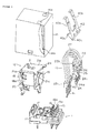
- Figure 1 is an exploded perspective view of an electromagnetic relay in an ideal embodiment of this invention.
- Figure 2 is a perspective drawing illustrating the process of producing the movable block shown in Figure 1.
- Figure 2(a) illustrates the state of the components before the primary molding process.
- Figure 2(b) illustrates their appearance after the primary molding process.
- Figure 2(c) illustrates the movable iron member before the primary molding process.
- Figure 2(d) illustrates the iron member after the primary molding process.
- Figure 2(e) illustrates the completed movable block.
- Figure 3 illustrates a cross section of the mold for the first retainer portion used in the primary molding process.
- Figure 4 illustrates a cross section of the mold for the second retainer portion used in the primary molding process.
- Figure 5(a) is a plan view of the movable block in Figure 1.
- Figure 5(b) illustrates a cross section taken along line A-A in Figure 5(a).
- Figure 6 illustrates a cross section of the electromagnetic relay in the ideal embodiment of this invention.
- Figure 7 illustrates a partial cross section showing another example of how the two retainer portions might be attached.
- Figure 8 illustrates a partial cross section showing still another example of how the two retainer portions might be attached.
- Figure 9 illustrates a cross section of an electromagnetic relay of the prior art.
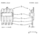
- Figure 10(a) is a frontal view of the movable component in Figure 9.
- Figure 10(b) is a lateral view of the component in Figure 10(a).
- Figure 1 illustrates an ideal embodiment of an electromagnetic relay of the invention. It comprises primarily of base 11, coil block 12, movable block 13 and case 14.
- Base 11 is a rectangular plate. On one end of this plate are four sets of fixed terminals 15 and 16 which are pressed into the base. Fixed contacts 15a and 16a, which are on these terminals, face each other with a prescribed gap between them. On the other end of base 11 are two coil terminals 17, which are pressed into the base close to its edges.
- core 19 is inserted into and through spool 18, and coil 20 is wound around it.
- An end of core 19 which projects beyond flange 18a of spool 18 is caulked to vertical wall 21a of yoke 21, which is attached to the base 11.
- Movable block 13 comprises movable component 22 and terminal 23.
- Movable component 22 comprises four movable contact elements 24 and movable iron member 25, which are formed integrally with retainer 26. Referring to in Figure 2(a), movable contacts 24a are on the corresponding ends of movable contact elements 24. Lead wires 27 are connected to the other ends of the elements.
- movable iron member 25 has a tab 25a protruding from the middle of one end. On either side of this tab are fulcrum ends 25b. Holes 25c are provided in two locations on top of the movable iron member 25. Fulcrum ends 25b of the movable member 25 are supported by tabs 21c on the ends of horizontal wall 21b of yoke 21.
- Retainer 26 comprises first retainer portion 28 and second retainer portion 29 (see Figures 2(b), 2(d) and 2(e)).
- First retainer portion 28 has an array of four movable contact elements 24 at prescribed intervals. These contact elements 24 are insert-molded into the connector portions of lead wires 27 in a primary molding process. Since there are no parts which require a sliding core as in the prior art, the primary molding process can be accomplished using two simply configured molds X 1 and Y 1 , as illustrated in Figure 3. Furthermore, the retainer can be molded with portions of movable contact elements 24 touching the inner surface Y 1 a of the cavity of direct mold Y 1 . Thus the distance x 1 between movable contact element 24 and the surface (surface 28a) of first retainer portion 28 can be kept within the range of allowable error in the molding process (in this embodiment, ⁇ 0.005 mm).
- a protrusion 28c is formed (see Figure 2(b)). Most of this surface is recessed to form depression 30. In the center of depression 30 is resin hole 31. On either side of protrusion 28c are resin holes 32. On either side of resin hole 31 are two connector holes 33. Projections 34 extend from two corners of first retainer portion 28.
- second retainer portion 29 is insert-molded in a primary molding process to form movable iron member 25 as a single piece. There is no need for a sliding core as in the prior art in this primary molding process.
- second retainer portion 29 can be molded with adsorbent surface 25a of movable iron member 25 in direct contact with inner surface Y 2 a of the cavity of mold Y 2 . Thus any variations in the thickness of the sheet or the plating of member 25 will be absorbed in the molding process.
- the distance x 2 between the adsorbent surface 25a of the member 25 and the opposing surface on the other side of member 25 (contacting surface 29a) can be kept within the permissible range of error (in this embodiment, ⁇ 0.005 mm) by the molding process.
- On the opposite edges of second retainer portion 29 are two L-shaped protrusions 37.
- the first and second retainer portions 28 and 29 are then formed into a single piece by means of an insert molding process (postforming).
- the first step in this secondary process is to put surface 28a of the first retainer portion 28 in contact with surface 29a of the second retainer portion 29. Projections 34 on the second retainer portion 29 will engage in holes 33 in the first retainer portion 28 to temporarily anchor the two portions to each other.
- the dimension from movable contact element 24 to surface 28a of the first retainer portion 28, and the dimension from adsorbent surface 26a of the movable iron member 25 to surface 29a of the second retainer portion 29 are determined with a very high degree of precision.
- the dimension from movable contact element 24 to adsorbent surface 25a of movable contact element 25 is also precisely determined.
- the two temporarily anchored portions of the first and second retainer portions 28 and 29 are then placed in a cavity of a mold (not pictured) and the secondary molding process is executed.
- a resin P which is poured into the mold (see Figure 5(b)) fills depression 30 in the first retainer portion 28. It flows through resin hole 31 and then through holes 32 and 36 until it reaches the second retainer portion 29.
- the resin which flows through resin hole 31 goes beyond second retainer portion 29 and spreads wider than the diameter of hole 31. In this way, the first and seccnd retainer portions 28 and 29 are permanently joined together.
- Movable component 22 then, is created by forming the first and second retainer portions 28 and 29 into a single piece. Fulcrum ends 25b (see Figure 1) which support component 22 are themselves supported by tabs 21c of yoke 21 in a way that they are free to rotate. Spring 38 imparts force in the counterclockwise direction as shown in Figure 6.
- Operating indicator 40 is seated in support hole 39, which is formed from projections 34 on the first retainer portion 28 and protrusions 37 on the second retainer portion 29. Indicator 40 can freely rotate about its axis, shaft 40a, as shown in Figure 6. Operating indicator 40 has two arms 40b which extend upward, and a shaft 40c which protrudes to either side on its lower end.
- Terminal 23 has four rotor terminations 41 arranged in a row (see Figure 2(e)). These terminations are connected, respectively, to the other ends of the lead wires 27 which come from the movable contact elements 24. Terminal 23 is formed integraily with retainer component 42 during the primary molding process. Component 42 is pressed into a prescribed location on base 11; rotor terminations 41 protrude beyond the lower surface of base 11.
- case 14 is shaped like a box with no bottom. When it is installed on base 11, it encloses all the above-mentioned structural components. On both sides of the top surface of case 14, near its edges, are windows 14a. These are made of a transparent material so that a user may view arms 40a of operating indicator 40. On the inner surface of one of the side walls of case 14 is a stop 14b for controlling the rotation of the movable component. When the movable component 22 rotates, shaft 40c of operating indicator 40 hits stop 14b so that its position can be controlled.
- operating indicator 40 is moved to the left in Figure 6. Its movement is halted when its shaft 40c comes up against stop 14b on case 14. Indicator 40, then, rotates counterclockwise on shaft 40a, and the tops of arms 40b end up just below windows 15a in case 14, where they are visible from the exterior. This allows the user to determine whether movable component 22 is operating properly.
- first and second retainer portions 28 and 29 are combined in the secondary molding process. It is also possible, however, to attach these retainer portions in the following way.
- a projection 43 is provided on the first retainer portion 28, and a hole 44 is created in the second retainer portion 29 and movable iron member 25, into which this projection is fitted. (Or, alternatively, a hole is provided in the first retainer portion 28 and a projection molded on the second retainer portion 29 and member 25.)
- Projection 43 has a depression 43a on its end so that it can be caulked.
- the first and second retainer portions 28 and 29 are positioned so that their surfaces 28a and 29a are in contact with each other and then attached. Projection 43 is then inserted through hole 44 so that it protrudes beyond the surface on the other side.
- the protruding portion is then thermally caulked to permanently attach the first and second retainer portions 28 and 29.
- the depression 43a has a tip such that when it is thermally caulked, it easily spreads to the edges cf hole 44 to ensure a secure attachment.
- first and second retainer portions 28 and 29 are thermally caulked together to form a single component; it is also possible to fasten the two portions together simply by caulking the tip of projection 43.
- FIG. 8 there is shown a hole 45 going through both the first and second retainer portions 28 and 29.
- the contacting surfaces 28a and 29a of the first and second retainer portions 28 and 29, respectively are placed together and the portions attached to one another.
- a rivet 46 is then inserted through the hole 45, and both its ends are caulked to form the first and second retainer portions 28 and 29 into a single piece.
- the electromagnetic relay according to this invention is constructed using a component which comprises both a movable contact element and a movable iron member.
- This component comprises two portions of a retainer, one of which retains the movable contact element and the other retains the movable iron member.
- This design obviates the need for a sliding core in the molding process, which is a requirement in the prior art. Consequently, a simpler mold can be used, resulting in a lower production cost.
- the molding process which produces the second retainer portion absorbs any imperfections which may have occurred in processing the surface of the movable iron member. As a result, the finished relay has an extremely high degree of precision.
- a small projection is provided on one of the pieces and a small hole is provided on the other to serve as a temporary anchor.
- the projection is engaged in the hole, the pieces cannot slip apart in the secondary molding process, and the quality of the work is improved.
- Support holes are provided through tabs on both retainer portions into which a shaft of an operating indicator is inserted.
- the indicator is seated in the holes in a way that it is free to rotate. This design provides a simple and inexpensive way for the indicator to be made integral to the relay.
Landscapes
- Physics & Mathematics (AREA)
- Electromagnetism (AREA)
- Manufacture Of Switches (AREA)
- Electromagnets (AREA)
- Tumbler Switches (AREA)
Applications Claiming Priority (3)
| Application Number | Priority Date | Filing Date | Title |
|---|---|---|---|
| JP1851397 | 1997-01-31 | ||
| JP18513/97 | 1997-01-31 | ||
| JP01851397A JP3832004B2 (ja) | 1997-01-31 | 1997-01-31 | 電磁継電器 |
Publications (3)
| Publication Number | Publication Date |
|---|---|
| EP0856865A2 true EP0856865A2 (fr) | 1998-08-05 |
| EP0856865A3 EP0856865A3 (fr) | 1999-02-03 |
| EP0856865B1 EP0856865B1 (fr) | 2005-04-27 |
Family
ID=11973718
Family Applications (1)
| Application Number | Title | Priority Date | Filing Date |
|---|---|---|---|
| EP98101751A Expired - Lifetime EP0856865B1 (fr) | 1997-01-31 | 1998-02-02 | Relais électromagnétique |
Country Status (5)
| Country | Link |
|---|---|
| US (1) | US5986529A (fr) |
| EP (1) | EP0856865B1 (fr) |
| JP (1) | JP3832004B2 (fr) |
| CN (1) | CN1175451C (fr) |
| DE (1) | DE69829898T2 (fr) |
Cited By (1)
| Publication number | Priority date | Publication date | Assignee | Title |
|---|---|---|---|---|
| EP1471555A3 (fr) * | 2003-04-24 | 2006-07-05 | Omron Corporation | Relais électromagnétique |
Families Citing this family (14)
| Publication number | Priority date | Publication date | Assignee | Title |
|---|---|---|---|---|
| DE69834273T2 (de) * | 1998-10-20 | 2007-01-18 | Releco, S.A., Alcorcon | Elektromagnetisches relais |
| US6771154B1 (en) * | 1999-11-12 | 2004-08-03 | Taiko Device, Ltd. | Electromagnetic relay |
| JP4140432B2 (ja) * | 2003-04-24 | 2008-08-27 | オムロン株式会社 | 電磁継電器 |
| CN1332407C (zh) * | 2004-01-30 | 2007-08-15 | 厦门宏发电声有限公司 | 低高度小型大功率多组触点交直流电磁继电器 |
| ITPC20050006U1 (it) * | 2005-03-10 | 2006-09-11 | Electrica Srl | Rele' voltmetrico con base sagomata che presenta incavi atti a costituire sedi per l'inserimento di attacchi tipo "faston" |
| JP5864960B2 (ja) * | 2011-09-01 | 2016-02-17 | 富士通コンポーネント株式会社 | 電磁継電器 |
| CN105359243B (zh) * | 2013-06-28 | 2018-06-05 | 松下知识产权经营株式会社 | 触点装置以及搭载有该触点装置的电磁继电器 |
| CN106463281A (zh) * | 2014-01-20 | 2017-02-22 | 赛特勒电子有限公司 | 用于大功率继电器的触头装置 |
| JP2015153564A (ja) * | 2014-02-13 | 2015-08-24 | Necトーキン株式会社 | 電磁継電器 |
| USD772819S1 (en) * | 2014-03-04 | 2016-11-29 | Omron Corporation | Relay |
| JP6414453B2 (ja) * | 2014-12-05 | 2018-10-31 | オムロン株式会社 | 電磁継電器 |
| JP2016110843A (ja) | 2014-12-05 | 2016-06-20 | オムロン株式会社 | 電磁継電器 |
| CN106716588B (zh) | 2014-12-05 | 2020-01-21 | 欧姆龙株式会社 | 电磁继电器 |
| KR101943365B1 (ko) * | 2015-10-14 | 2019-01-29 | 엘에스산전 주식회사 | 직류 릴레이 |
Family Cites Families (2)
| Publication number | Priority date | Publication date | Assignee | Title |
|---|---|---|---|---|
| JP2502989Y2 (ja) * | 1989-11-30 | 1996-06-26 | 自動車電機工業株式会社 | 電磁継電器 |
| DE4309618A1 (de) * | 1993-03-24 | 1994-09-29 | Siemens Ag | Polarisiertes elektromagnetisches Relais |
-
1997
- 1997-01-31 JP JP01851397A patent/JP3832004B2/ja not_active Expired - Lifetime
-
1998
- 1998-01-25 CN CNB981043909A patent/CN1175451C/zh not_active Expired - Lifetime
- 1998-02-02 DE DE69829898T patent/DE69829898T2/de not_active Expired - Lifetime
- 1998-02-02 US US09/017,253 patent/US5986529A/en not_active Expired - Lifetime
- 1998-02-02 EP EP98101751A patent/EP0856865B1/fr not_active Expired - Lifetime
Cited By (1)
| Publication number | Priority date | Publication date | Assignee | Title |
|---|---|---|---|---|
| EP1471555A3 (fr) * | 2003-04-24 | 2006-07-05 | Omron Corporation | Relais électromagnétique |
Also Published As
| Publication number | Publication date |
|---|---|
| US5986529A (en) | 1999-11-16 |
| DE69829898T2 (de) | 2006-02-23 |
| JP3832004B2 (ja) | 2006-10-11 |
| CN1192034A (zh) | 1998-09-02 |
| CN1175451C (zh) | 2004-11-10 |
| JPH10214554A (ja) | 1998-08-11 |
| DE69829898D1 (de) | 2005-06-02 |
| EP0856865B1 (fr) | 2005-04-27 |
| EP0856865A3 (fr) | 1999-02-03 |
Similar Documents
| Publication | Publication Date | Title |
|---|---|---|
| US5986529A (en) | Electromagnetic relay | |
| US20050057332A1 (en) | Complex electromagnetic relay | |
| JP4471859B2 (ja) | 電磁継電器 | |
| US4730176A (en) | Electromagnet having a pivoted polarized armature | |
| US4713638A (en) | Polarized electromagnetic relay | |
| EP0487069B1 (fr) | Relais électromagnétique | |
| JPH02250230A (ja) | 電磁接触器 | |
| GB2214356A (en) | Electromagnetic plunger | |
| JPH01302631A (ja) | 電磁継電器 | |
| JP3826464B2 (ja) | 電磁継電器 | |
| JPS648419B2 (fr) | ||
| JPH06139891A (ja) | 電磁継電器 | |
| JPH08195154A (ja) | 電磁リレー | |
| JP2543903Y2 (ja) | 電磁継電器 | |
| JPH0438495Y2 (fr) | ||
| JPH06267392A (ja) | 電磁継電器 | |
| JP4089188B2 (ja) | 電磁継電器 | |
| JPH086356Y2 (ja) | 電磁継電器 | |
| JPS6235245Y2 (fr) | ||
| JP2724371B2 (ja) | 電磁継電器 | |
| JP4089189B2 (ja) | 電磁継電器 | |
| JPH10188762A (ja) | 電磁リレー | |
| JPH0322834Y2 (fr) | ||
| JPH0718117Y2 (ja) | 電磁継電器 | |
| JP4151248B2 (ja) | 電磁継電器 |
Legal Events
| Date | Code | Title | Description |
|---|---|---|---|
| PUAI | Public reference made under article 153(3) epc to a published international application that has entered the european phase |
Free format text: ORIGINAL CODE: 0009012 |
|
| 17P | Request for examination filed |
Effective date: 19980227 |
|
| AK | Designated contracting states |
Kind code of ref document: A2 Designated state(s): DE FR GB IT |
|
| AX | Request for extension of the european patent |
Free format text: AL;LT;LV;MK;RO;SI |
|
| PUAL | Search report despatched |
Free format text: ORIGINAL CODE: 0009013 |
|
| AK | Designated contracting states |
Kind code of ref document: A3 Designated state(s): AT BE CH DE DK ES FI FR GB GR IE IT LI LU MC NL PT SE |
|
| AX | Request for extension of the european patent |
Free format text: AL;LT;LV;MK;RO;SI |
|
| AKX | Designation fees paid |
Free format text: DE FR GB IT |
|
| 17Q | First examination report despatched |
Effective date: 20030818 |
|
| GRAP | Despatch of communication of intention to grant a patent |
Free format text: ORIGINAL CODE: EPIDOSNIGR1 |
|
| GRAS | Grant fee paid |
Free format text: ORIGINAL CODE: EPIDOSNIGR3 |
|
| GRAA | (expected) grant |
Free format text: ORIGINAL CODE: 0009210 |
|
| AK | Designated contracting states |
Kind code of ref document: B1 Designated state(s): DE FR GB IT |
|
| REG | Reference to a national code |
Ref country code: GB Ref legal event code: FG4D |
|
| REF | Corresponds to: |
Ref document number: 69829898 Country of ref document: DE Date of ref document: 20050602 Kind code of ref document: P |
|
| PLBE | No opposition filed within time limit |
Free format text: ORIGINAL CODE: 0009261 |
|
| STAA | Information on the status of an ep patent application or granted ep patent |
Free format text: STATUS: NO OPPOSITION FILED WITHIN TIME LIMIT |
|
| ET | Fr: translation filed | ||
| 26N | No opposition filed |
Effective date: 20060130 |
|
| REG | Reference to a national code |
Ref country code: DE Ref legal event code: R082 Ref document number: 69829898 Country of ref document: DE Representative=s name: KILIAN KILIAN & PARTNER MBB PATENTANWAELTE, DE Ref country code: DE Ref legal event code: R082 Ref document number: 69829898 Country of ref document: DE Representative=s name: KILIAN KILIAN & PARTNER, DE |
|
| REG | Reference to a national code |
Ref country code: FR Ref legal event code: PLFP Year of fee payment: 19 |
|
| REG | Reference to a national code |
Ref country code: FR Ref legal event code: PLFP Year of fee payment: 20 |
|
| PGFP | Annual fee paid to national office [announced via postgrant information from national office to epo] |
Ref country code: DE Payment date: 20170227 Year of fee payment: 20 Ref country code: FR Payment date: 20170222 Year of fee payment: 20 |
|
| PGFP | Annual fee paid to national office [announced via postgrant information from national office to epo] |
Ref country code: GB Payment date: 20170222 Year of fee payment: 20 |
|
| PGFP | Annual fee paid to national office [announced via postgrant information from national office to epo] |
Ref country code: IT Payment date: 20170206 Year of fee payment: 20 |
|
| REG | Reference to a national code |
Ref country code: DE Ref legal event code: R071 Ref document number: 69829898 Country of ref document: DE |
|
| REG | Reference to a national code |
Ref country code: GB Ref legal event code: PE20 Expiry date: 20180201 |
|
| PG25 | Lapsed in a contracting state [announced via postgrant information from national office to epo] |
Ref country code: GB Free format text: LAPSE BECAUSE OF EXPIRATION OF PROTECTION Effective date: 20180201 |