EP0857767A1 - Encre d'heliogravure durable et utilisations de celle-ci - Google Patents
Encre d'heliogravure durable et utilisations de celle-ci Download PDFInfo
- Publication number
- EP0857767A1 EP0857767A1 EP97937822A EP97937822A EP0857767A1 EP 0857767 A1 EP0857767 A1 EP 0857767A1 EP 97937822 A EP97937822 A EP 97937822A EP 97937822 A EP97937822 A EP 97937822A EP 0857767 A1 EP0857767 A1 EP 0857767A1
- Authority
- EP
- European Patent Office
- Prior art keywords
- pigment
- weather resistance
- alkali resistance
- resistance
- solid particles
- Prior art date
- Legal status (The legal status is an assumption and is not a legal conclusion. Google has not performed a legal analysis and makes no representation as to the accuracy of the status listed.)
- Granted
Links
- 239000000049 pigment Substances 0.000 claims abstract description 62
- 239000003513 alkali Substances 0.000 claims abstract description 50
- 239000000463 material Substances 0.000 claims abstract description 47
- 239000011230 binding agent Substances 0.000 claims abstract description 27
- 238000000034 method Methods 0.000 claims abstract description 12
- 239000002245 particle Substances 0.000 claims description 94
- 239000007787 solid Substances 0.000 claims description 87
- 239000010410 layer Substances 0.000 claims description 53
- -1 polyazo Polymers 0.000 claims description 37
- 239000002585 base Substances 0.000 claims description 23
- 239000001054 red pigment Substances 0.000 claims description 20
- 239000001052 yellow pigment Substances 0.000 claims description 20
- 150000001875 compounds Chemical class 0.000 claims description 9
- 229920002433 Vinyl chloride-vinyl acetate copolymer Polymers 0.000 claims description 8
- MWPLVEDNUUSJAV-UHFFFAOYSA-N anthracene Chemical compound C1=CC=CC2=CC3=CC=CC=C3C=C21 MWPLVEDNUUSJAV-UHFFFAOYSA-N 0.000 claims description 8
- 239000003381 stabilizer Substances 0.000 claims description 8
- 239000004593 Epoxy Substances 0.000 claims description 7
- NRCMAYZCPIVABH-UHFFFAOYSA-N Quinacridone Chemical compound N1C2=CC=CC=C2C(=O)C2=C1C=C1C(=O)C3=CC=CC=C3NC1=C2 NRCMAYZCPIVABH-UHFFFAOYSA-N 0.000 claims description 7
- 125000002080 perylenyl group Chemical group C1(=CC=C2C=CC=C3C4=CC=CC5=CC=CC(C1=C23)=C45)* 0.000 claims description 5
- CSHWQDPOILHKBI-UHFFFAOYSA-N peryrene Natural products C1=CC(C2=CC=CC=3C2=C2C=CC=3)=C3C2=CC=CC3=C1 CSHWQDPOILHKBI-UHFFFAOYSA-N 0.000 claims description 5
- WZSFTHVIIGGDOI-UHFFFAOYSA-N 4,5,6,7-tetrachloro-3-[2-methyl-3-[(4,5,6,7-tetrachloro-3-oxoisoindol-1-yl)amino]anilino]isoindol-1-one Chemical compound ClC1=C(Cl)C(Cl)=C(Cl)C2=C1C(NC1=CC=CC(NC=3C4=C(C(=C(Cl)C(Cl)=C4Cl)Cl)C(=O)N=3)=C1C)=NC2=O WZSFTHVIIGGDOI-UHFFFAOYSA-N 0.000 claims description 4
- 239000012790 adhesive layer Substances 0.000 claims description 4
- 238000004519 manufacturing process Methods 0.000 claims description 2
- 239000000976 ink Substances 0.000 description 57
- 239000012530 fluid Substances 0.000 description 36
- 239000011324 bead Substances 0.000 description 16
- 239000007788 liquid Substances 0.000 description 16
- 239000000203 mixture Substances 0.000 description 15
- NIXOWILDQLNWCW-UHFFFAOYSA-M Acrylate Chemical compound [O-]C(=O)C=C NIXOWILDQLNWCW-UHFFFAOYSA-M 0.000 description 14
- 238000007664 blowing Methods 0.000 description 14
- 239000000123 paper Substances 0.000 description 14
- 238000005422 blasting Methods 0.000 description 11
- 238000010438 heat treatment Methods 0.000 description 11
- 229920005989 resin Polymers 0.000 description 11
- 239000011347 resin Substances 0.000 description 11
- 239000000853 adhesive Substances 0.000 description 10
- 230000001070 adhesive effect Effects 0.000 description 10
- 230000000052 comparative effect Effects 0.000 description 10
- 238000001816 cooling Methods 0.000 description 10
- HEMHJVSKTPXQMS-UHFFFAOYSA-M Sodium hydroxide Chemical compound [OH-].[Na+] HEMHJVSKTPXQMS-UHFFFAOYSA-M 0.000 description 9
- 239000007789 gas Substances 0.000 description 9
- 239000000919 ceramic Substances 0.000 description 8
- 239000004567 concrete Substances 0.000 description 8
- 230000005865 ionizing radiation Effects 0.000 description 8
- 239000004570 mortar (masonry) Substances 0.000 description 8
- 239000000178 monomer Substances 0.000 description 7
- ZWEHNKRNPOVVGH-UHFFFAOYSA-N 2-Butanone Chemical compound CCC(C)=O ZWEHNKRNPOVVGH-UHFFFAOYSA-N 0.000 description 6
- LYCAIKOWRPUZTN-UHFFFAOYSA-N Ethylene glycol Chemical compound OCCO LYCAIKOWRPUZTN-UHFFFAOYSA-N 0.000 description 6
- YXFVVABEGXRONW-UHFFFAOYSA-N Toluene Chemical compound CC1=CC=CC=C1 YXFVVABEGXRONW-UHFFFAOYSA-N 0.000 description 6
- 239000006229 carbon black Substances 0.000 description 6
- 125000002091 cationic group Chemical group 0.000 description 6
- XCJYREBRNVKWGJ-UHFFFAOYSA-N copper(II) phthalocyanine Chemical compound [Cu+2].C12=CC=CC=C2C(N=C2[N-]C(C3=CC=CC=C32)=N2)=NC1=NC([C]1C=CC=CC1=1)=NC=1N=C1[C]3C=CC=CC3=C2[N-]1 XCJYREBRNVKWGJ-UHFFFAOYSA-N 0.000 description 6
- 238000002845 discoloration Methods 0.000 description 6
- 125000000524 functional group Chemical group 0.000 description 6
- XLYOFNOQVPJJNP-UHFFFAOYSA-N water Substances O XLYOFNOQVPJJNP-UHFFFAOYSA-N 0.000 description 6
- RTAQQCXQSZGOHL-UHFFFAOYSA-N Titanium Chemical compound [Ti] RTAQQCXQSZGOHL-UHFFFAOYSA-N 0.000 description 5
- 238000005034 decoration Methods 0.000 description 5
- 238000005562 fading Methods 0.000 description 5
- 229920000728 polyester Polymers 0.000 description 5
- 239000012508 resin bead Substances 0.000 description 5
- 239000002904 solvent Substances 0.000 description 5
- 239000000126 substance Substances 0.000 description 5
- 239000010936 titanium Substances 0.000 description 5
- 229910052719 titanium Inorganic materials 0.000 description 5
- VTYYLEPIZMXCLO-UHFFFAOYSA-L Calcium carbonate Chemical compound [Ca+2].[O-]C([O-])=O VTYYLEPIZMXCLO-UHFFFAOYSA-L 0.000 description 4
- VYPSYNLAJGMNEJ-UHFFFAOYSA-N Silicium dioxide Chemical compound O=[Si]=O VYPSYNLAJGMNEJ-UHFFFAOYSA-N 0.000 description 4
- 229910000831 Steel Inorganic materials 0.000 description 4
- 239000001055 blue pigment Substances 0.000 description 4
- 230000000694 effects Effects 0.000 description 4
- 229920001971 elastomer Polymers 0.000 description 4
- 239000003822 epoxy resin Substances 0.000 description 4
- 239000000835 fiber Substances 0.000 description 4
- 239000010440 gypsum Substances 0.000 description 4
- 229910052602 gypsum Inorganic materials 0.000 description 4
- LNEPOXFFQSENCJ-UHFFFAOYSA-N haloperidol Chemical compound C1CC(O)(C=2C=CC(Cl)=CC=2)CCN1CCCC(=O)C1=CC=C(F)C=C1 LNEPOXFFQSENCJ-UHFFFAOYSA-N 0.000 description 4
- 239000003999 initiator Substances 0.000 description 4
- 229920000647 polyepoxide Polymers 0.000 description 4
- 229920000642 polymer Polymers 0.000 description 4
- 229920000915 polyvinyl chloride Polymers 0.000 description 4
- 239000004800 polyvinyl chloride Substances 0.000 description 4
- 238000007639 printing Methods 0.000 description 4
- 150000003254 radicals Chemical class 0.000 description 4
- 239000005060 rubber Substances 0.000 description 4
- 239000010959 steel Substances 0.000 description 4
- TXBCBTDQIULDIA-UHFFFAOYSA-N 2-[[3-hydroxy-2,2-bis(hydroxymethyl)propoxy]methyl]-2-(hydroxymethyl)propane-1,3-diol Chemical compound OCC(CO)(CO)COCC(CO)(CO)CO TXBCBTDQIULDIA-UHFFFAOYSA-N 0.000 description 3
- 229920000178 Acrylic resin Polymers 0.000 description 3
- 239000004925 Acrylic resin Substances 0.000 description 3
- XEKOWRVHYACXOJ-UHFFFAOYSA-N Ethyl acetate Chemical compound CCOC(C)=O XEKOWRVHYACXOJ-UHFFFAOYSA-N 0.000 description 3
- KFZMGEQAYNKOFK-UHFFFAOYSA-N Isopropanol Chemical compound CC(C)O KFZMGEQAYNKOFK-UHFFFAOYSA-N 0.000 description 3
- 239000004952 Polyamide Substances 0.000 description 3
- 239000004743 Polypropylene Substances 0.000 description 3
- 229910001069 Ti alloy Inorganic materials 0.000 description 3
- QYKIQEUNHZKYBP-UHFFFAOYSA-N Vinyl ether Chemical class C=COC=C QYKIQEUNHZKYBP-UHFFFAOYSA-N 0.000 description 3
- PNEYBMLMFCGWSK-UHFFFAOYSA-N aluminium oxide Inorganic materials [O-2].[O-2].[O-2].[Al+3].[Al+3] PNEYBMLMFCGWSK-UHFFFAOYSA-N 0.000 description 3
- 239000007864 aqueous solution Substances 0.000 description 3
- ISAOCJYIOMOJEB-UHFFFAOYSA-N benzoin Chemical compound C=1C=CC=CC=1C(O)C(=O)C1=CC=CC=C1 ISAOCJYIOMOJEB-UHFFFAOYSA-N 0.000 description 3
- 238000000576 coating method Methods 0.000 description 3
- 239000003086 colorant Substances 0.000 description 3
- MTHSVFCYNBDYFN-UHFFFAOYSA-N diethylene glycol Chemical compound OCCOCCO MTHSVFCYNBDYFN-UHFFFAOYSA-N 0.000 description 3
- 239000005038 ethylene vinyl acetate Substances 0.000 description 3
- 238000007646 gravure printing Methods 0.000 description 3
- 238000002347 injection Methods 0.000 description 3
- 239000007924 injection Substances 0.000 description 3
- 230000001788 irregular Effects 0.000 description 3
- PXZQEOJJUGGUIB-UHFFFAOYSA-N isoindolin-1-one Chemical compound C1=CC=C2C(=O)NCC2=C1 PXZQEOJJUGGUIB-UHFFFAOYSA-N 0.000 description 3
- 229910052751 metal Inorganic materials 0.000 description 3
- 239000002184 metal Substances 0.000 description 3
- NYGZLYXAPMMJTE-UHFFFAOYSA-M metanil yellow Chemical group [Na+].[O-]S(=O)(=O)C1=CC=CC(N=NC=2C=CC(NC=3C=CC=CC=3)=CC=2)=C1 NYGZLYXAPMMJTE-UHFFFAOYSA-M 0.000 description 3
- 229920001200 poly(ethylene-vinyl acetate) Polymers 0.000 description 3
- 229920002647 polyamide Polymers 0.000 description 3
- 229920000570 polyether Polymers 0.000 description 3
- 229920005862 polyol Polymers 0.000 description 3
- 229920001155 polypropylene Polymers 0.000 description 3
- 229920002635 polyurethane Polymers 0.000 description 3
- 239000004814 polyurethane Substances 0.000 description 3
- 230000005855 radiation Effects 0.000 description 3
- 239000007921 spray Substances 0.000 description 3
- 241000251468 Actinopterygii Species 0.000 description 2
- IJGRMHOSHXDMSA-UHFFFAOYSA-N Atomic nitrogen Chemical compound N#N IJGRMHOSHXDMSA-UHFFFAOYSA-N 0.000 description 2
- OKTJSMMVPCPJKN-UHFFFAOYSA-N Carbon Chemical compound [C] OKTJSMMVPCPJKN-UHFFFAOYSA-N 0.000 description 2
- 229920000049 Carbon (fiber) Polymers 0.000 description 2
- CURLTUGMZLYLDI-UHFFFAOYSA-N Carbon dioxide Chemical compound O=C=O CURLTUGMZLYLDI-UHFFFAOYSA-N 0.000 description 2
- VYZAMTAEIAYCRO-UHFFFAOYSA-N Chromium Chemical compound [Cr] VYZAMTAEIAYCRO-UHFFFAOYSA-N 0.000 description 2
- 229910001208 Crucible steel Inorganic materials 0.000 description 2
- LFQSCWFLJHTTHZ-UHFFFAOYSA-N Ethanol Chemical compound CCO LFQSCWFLJHTTHZ-UHFFFAOYSA-N 0.000 description 2
- 229920002430 Fibre-reinforced plastic Polymers 0.000 description 2
- PEDCQBHIVMGVHV-UHFFFAOYSA-N Glycerine Chemical compound OCC(O)CO PEDCQBHIVMGVHV-UHFFFAOYSA-N 0.000 description 2
- XEEYBQQBJWHFJM-UHFFFAOYSA-N Iron Chemical compound [Fe] XEEYBQQBJWHFJM-UHFFFAOYSA-N 0.000 description 2
- UQSXHKLRYXJYBZ-UHFFFAOYSA-N Iron oxide Chemical compound [Fe]=O UQSXHKLRYXJYBZ-UHFFFAOYSA-N 0.000 description 2
- 229920000877 Melamine resin Polymers 0.000 description 2
- LRHPLDYGYMQRHN-UHFFFAOYSA-N N-Butanol Chemical compound CCCCO LRHPLDYGYMQRHN-UHFFFAOYSA-N 0.000 description 2
- 229920002292 Nylon 6 Polymers 0.000 description 2
- 229920002302 Nylon 6,6 Polymers 0.000 description 2
- 239000004698 Polyethylene Substances 0.000 description 2
- 239000004721 Polyphenylene oxide Substances 0.000 description 2
- 244000028419 Styrax benzoin Species 0.000 description 2
- 235000000126 Styrax benzoin Nutrition 0.000 description 2
- 235000008411 Sumatra benzointree Nutrition 0.000 description 2
- MCMNRKCIXSYSNV-UHFFFAOYSA-N Zirconium dioxide Chemical compound O=[Zr]=O MCMNRKCIXSYSNV-UHFFFAOYSA-N 0.000 description 2
- 238000005299 abrasion Methods 0.000 description 2
- 230000001133 acceleration Effects 0.000 description 2
- NIXOWILDQLNWCW-UHFFFAOYSA-N acrylic acid group Chemical group C(C=C)(=O)O NIXOWILDQLNWCW-UHFFFAOYSA-N 0.000 description 2
- 239000010425 asbestos Substances 0.000 description 2
- TZCXTZWJZNENPQ-UHFFFAOYSA-L barium sulfate Chemical compound [Ba+2].[O-]S([O-])(=O)=O TZCXTZWJZNENPQ-UHFFFAOYSA-L 0.000 description 2
- 229960002130 benzoin Drugs 0.000 description 2
- 239000012965 benzophenone Substances 0.000 description 2
- 230000015572 biosynthetic process Effects 0.000 description 2
- 229910000019 calcium carbonate Inorganic materials 0.000 description 2
- 239000000378 calcium silicate Substances 0.000 description 2
- 229910052918 calcium silicate Inorganic materials 0.000 description 2
- OYACROKNLOSFPA-UHFFFAOYSA-N calcium;dioxido(oxo)silane Chemical compound [Ca+2].[O-][Si]([O-])=O OYACROKNLOSFPA-UHFFFAOYSA-N 0.000 description 2
- 229910052799 carbon Inorganic materials 0.000 description 2
- 239000004917 carbon fiber Substances 0.000 description 2
- 229910052804 chromium Inorganic materials 0.000 description 2
- 239000011651 chromium Substances 0.000 description 2
- 238000005253 cladding Methods 0.000 description 2
- 239000011248 coating agent Substances 0.000 description 2
- 239000002131 composite material Substances 0.000 description 2
- 229920001577 copolymer Polymers 0.000 description 2
- 238000004132 cross linking Methods 0.000 description 2
- JHIVVAPYMSGYDF-UHFFFAOYSA-N cyclohexanone Chemical compound O=C1CCCCC1 JHIVVAPYMSGYDF-UHFFFAOYSA-N 0.000 description 2
- 238000001035 drying Methods 0.000 description 2
- 150000002148 esters Chemical class 0.000 description 2
- 229920006242 ethylene acrylic acid copolymer Polymers 0.000 description 2
- 239000011151 fibre-reinforced plastic Substances 0.000 description 2
- 239000011381 foam concrete Substances 0.000 description 2
- 239000011521 glass Substances 0.000 description 2
- 239000011211 glass fiber reinforced concrete Substances 0.000 description 2
- 235000019382 gum benzoic Nutrition 0.000 description 2
- 229930195733 hydrocarbon Natural products 0.000 description 2
- 150000002430 hydrocarbons Chemical group 0.000 description 2
- 238000007654 immersion Methods 0.000 description 2
- 239000010954 inorganic particle Substances 0.000 description 2
- 229920000554 ionomer Polymers 0.000 description 2
- HJOVHMDZYOCNQW-UHFFFAOYSA-N isophorone Chemical compound CC1=CC(=O)CC(C)(C)C1 HJOVHMDZYOCNQW-UHFFFAOYSA-N 0.000 description 2
- 239000002655 kraft paper Substances 0.000 description 2
- 150000002739 metals Chemical class 0.000 description 2
- 239000011088 parchment paper Substances 0.000 description 2
- 229920000573 polyethylene Polymers 0.000 description 2
- 229920000139 polyethylene terephthalate Polymers 0.000 description 2
- 239000005020 polyethylene terephthalate Substances 0.000 description 2
- 229920005672 polyolefin resin Polymers 0.000 description 2
- 150000003077 polyols Chemical class 0.000 description 2
- 238000003825 pressing Methods 0.000 description 2
- 229910052895 riebeckite Inorganic materials 0.000 description 2
- 239000000377 silicon dioxide Substances 0.000 description 2
- 229920002050 silicone resin Polymers 0.000 description 2
- 239000010935 stainless steel Substances 0.000 description 2
- 229910001220 stainless steel Inorganic materials 0.000 description 2
- 125000003396 thiol group Chemical group [H]S* 0.000 description 2
- 125000000391 vinyl group Chemical group [H]C([*])=C([H])[H] 0.000 description 2
- 229920002554 vinyl polymer Polymers 0.000 description 2
- JYEUMXHLPRZUAT-UHFFFAOYSA-N 1,2,3-triazine Chemical compound C1=CN=NN=C1 JYEUMXHLPRZUAT-UHFFFAOYSA-N 0.000 description 1
- OSNILPMOSNGHLC-UHFFFAOYSA-N 1-[4-methoxy-3-(piperidin-1-ylmethyl)phenyl]ethanone Chemical compound COC1=CC=C(C(C)=O)C=C1CN1CCCCC1 OSNILPMOSNGHLC-UHFFFAOYSA-N 0.000 description 1
- KAJBSGLXSREIHP-UHFFFAOYSA-N 2,2-bis[(2-sulfanylacetyl)oxymethyl]butyl 2-sulfanylacetate Chemical compound SCC(=O)OCC(CC)(COC(=O)CS)COC(=O)CS KAJBSGLXSREIHP-UHFFFAOYSA-N 0.000 description 1
- FWLHAQYOFMQTHQ-UHFFFAOYSA-N 2-N-[8-[[8-(4-aminoanilino)-10-phenylphenazin-10-ium-2-yl]amino]-10-phenylphenazin-10-ium-2-yl]-8-N,10-diphenylphenazin-10-ium-2,8-diamine hydroxy-oxido-dioxochromium Chemical compound O[Cr]([O-])(=O)=O.O[Cr]([O-])(=O)=O.O[Cr]([O-])(=O)=O.Nc1ccc(Nc2ccc3nc4ccc(Nc5ccc6nc7ccc(Nc8ccc9nc%10ccc(Nc%11ccccc%11)cc%10[n+](-c%10ccccc%10)c9c8)cc7[n+](-c7ccccc7)c6c5)cc4[n+](-c4ccccc4)c3c2)cc1 FWLHAQYOFMQTHQ-UHFFFAOYSA-N 0.000 description 1
- ZNQVEEAIQZEUHB-UHFFFAOYSA-N 2-ethoxyethanol Chemical compound CCOCCO ZNQVEEAIQZEUHB-UHFFFAOYSA-N 0.000 description 1
- RSROEZYGRKHVMN-UHFFFAOYSA-N 2-ethyl-2-(hydroxymethyl)propane-1,3-diol;oxirane Chemical compound C1CO1.CCC(CO)(CO)CO RSROEZYGRKHVMN-UHFFFAOYSA-N 0.000 description 1
- BQZJOQXSCSZQPS-UHFFFAOYSA-N 2-methoxy-1,2-diphenylethanone Chemical compound C=1C=CC=CC=1C(OC)C(=O)C1=CC=CC=C1 BQZJOQXSCSZQPS-UHFFFAOYSA-N 0.000 description 1
- KXGFMDJXCMQABM-UHFFFAOYSA-N 2-methoxy-6-methylphenol Chemical compound [CH]OC1=CC=CC([CH])=C1O KXGFMDJXCMQABM-UHFFFAOYSA-N 0.000 description 1
- ALYNCZNDIQEVRV-UHFFFAOYSA-N 4-aminobenzoic acid Chemical compound NC1=CC=C(C(O)=O)C=C1 ALYNCZNDIQEVRV-UHFFFAOYSA-N 0.000 description 1
- RSWGJHLUYNHPMX-UHFFFAOYSA-N Abietic-Saeure Natural products C12CCC(C(C)C)=CC2=CCC2C1(C)CCCC2(C)C(O)=O RSWGJHLUYNHPMX-UHFFFAOYSA-N 0.000 description 1
- NLHHRLWOUZZQLW-UHFFFAOYSA-N Acrylonitrile Chemical compound C=CC#N NLHHRLWOUZZQLW-UHFFFAOYSA-N 0.000 description 1
- 229910000838 Al alloy Inorganic materials 0.000 description 1
- DKPFZGUDAPQIHT-UHFFFAOYSA-N Butyl acetate Natural products CCCCOC(C)=O DKPFZGUDAPQIHT-UHFFFAOYSA-N 0.000 description 1
- 229910000975 Carbon steel Inorganic materials 0.000 description 1
- 229920001651 Cyanoacrylate Polymers 0.000 description 1
- 229910000737 Duralumin Inorganic materials 0.000 description 1
- JOYRKODLDBILNP-UHFFFAOYSA-N Ethyl urethane Chemical compound CCOC(N)=O JOYRKODLDBILNP-UHFFFAOYSA-N 0.000 description 1
- 229910000640 Fe alloy Inorganic materials 0.000 description 1
- 239000004606 Fillers/Extenders Substances 0.000 description 1
- PNKUSGQVOMIXLU-UHFFFAOYSA-N Formamidine Chemical compound NC=N PNKUSGQVOMIXLU-UHFFFAOYSA-N 0.000 description 1
- 239000005057 Hexamethylene diisocyanate Substances 0.000 description 1
- 239000004640 Melamine resin Substances 0.000 description 1
- MWCLLHOVUTZFKS-UHFFFAOYSA-N Methyl cyanoacrylate Chemical compound COC(=O)C(=C)C#N MWCLLHOVUTZFKS-UHFFFAOYSA-N 0.000 description 1
- NTIZESTWPVYFNL-UHFFFAOYSA-N Methyl isobutyl ketone Chemical compound CC(C)CC(C)=O NTIZESTWPVYFNL-UHFFFAOYSA-N 0.000 description 1
- UIHCLUNTQKBZGK-UHFFFAOYSA-N Methyl isobutyl ketone Natural products CCC(C)C(C)=O UIHCLUNTQKBZGK-UHFFFAOYSA-N 0.000 description 1
- 239000000020 Nitrocellulose Substances 0.000 description 1
- 239000004677 Nylon Substances 0.000 description 1
- CTQNGGLPUBDAKN-UHFFFAOYSA-N O-Xylene Chemical compound CC1=CC=CC=C1C CTQNGGLPUBDAKN-UHFFFAOYSA-N 0.000 description 1
- 239000002033 PVDF binder Substances 0.000 description 1
- 229920012485 Plasticized Polyvinyl chloride Polymers 0.000 description 1
- 239000004372 Polyvinyl alcohol Substances 0.000 description 1
- KHPCPRHQVVSZAH-HUOMCSJISA-N Rosin Natural products O(C/C=C/c1ccccc1)[C@H]1[C@H](O)[C@@H](O)[C@@H](O)[C@@H](CO)O1 KHPCPRHQVVSZAH-HUOMCSJISA-N 0.000 description 1
- GWEVSGVZZGPLCZ-UHFFFAOYSA-N Titan oxide Chemical compound O=[Ti]=O GWEVSGVZZGPLCZ-UHFFFAOYSA-N 0.000 description 1
- ZJCCRDAZUWHFQH-UHFFFAOYSA-N Trimethylolpropane Chemical compound CCC(CO)(CO)CO ZJCCRDAZUWHFQH-UHFFFAOYSA-N 0.000 description 1
- 229920001807 Urea-formaldehyde Polymers 0.000 description 1
- 229920002978 Vinylon Polymers 0.000 description 1
- HCHKCACWOHOZIP-UHFFFAOYSA-N Zinc Chemical compound [Zn] HCHKCACWOHOZIP-UHFFFAOYSA-N 0.000 description 1
- 239000006096 absorbing agent Substances 0.000 description 1
- 238000006359 acetalization reaction Methods 0.000 description 1
- TUVYSBJZBYRDHP-UHFFFAOYSA-N acetic acid;methoxymethane Chemical compound COC.CC(O)=O TUVYSBJZBYRDHP-UHFFFAOYSA-N 0.000 description 1
- 150000008062 acetophenones Chemical class 0.000 description 1
- 150000001252 acrylic acid derivatives Chemical class 0.000 description 1
- 125000003647 acryloyl group Chemical group O=C([*])C([H])=C([H])[H] 0.000 description 1
- 230000001464 adherent effect Effects 0.000 description 1
- 150000001298 alcohols Chemical class 0.000 description 1
- 125000001931 aliphatic group Chemical group 0.000 description 1
- 150000001336 alkenes Chemical class 0.000 description 1
- 229910052782 aluminium Inorganic materials 0.000 description 1
- XAGFODPZIPBFFR-UHFFFAOYSA-N aluminium Chemical compound [Al] XAGFODPZIPBFFR-UHFFFAOYSA-N 0.000 description 1
- 150000001412 amines Chemical class 0.000 description 1
- 229960004050 aminobenzoic acid Drugs 0.000 description 1
- 150000001454 anthracenes Chemical class 0.000 description 1
- 239000003963 antioxidant agent Substances 0.000 description 1
- 125000003118 aryl group Chemical group 0.000 description 1
- WPYMKLBDIGXBTP-UHFFFAOYSA-N benzoic acid Chemical compound OC(=O)C1=CC=CC=C1 WPYMKLBDIGXBTP-UHFFFAOYSA-N 0.000 description 1
- RWCCWEUUXYIKHB-UHFFFAOYSA-N benzophenone Chemical compound C=1C=CC=CC=1C(=O)C1=CC=CC=C1 RWCCWEUUXYIKHB-UHFFFAOYSA-N 0.000 description 1
- 150000008366 benzophenones Chemical class 0.000 description 1
- QRUDEWIWKLJBPS-UHFFFAOYSA-N benzotriazole Chemical compound C1=CC=C2N[N][N]C2=C1 QRUDEWIWKLJBPS-UHFFFAOYSA-N 0.000 description 1
- 239000012964 benzotriazole Substances 0.000 description 1
- 239000004566 building material Substances 0.000 description 1
- 239000001569 carbon dioxide Substances 0.000 description 1
- 229910002092 carbon dioxide Inorganic materials 0.000 description 1
- 239000010962 carbon steel Substances 0.000 description 1
- 239000004568 cement Substances 0.000 description 1
- 238000010276 construction Methods 0.000 description 1
- 238000005260 corrosion Methods 0.000 description 1
- 230000007797 corrosion Effects 0.000 description 1
- 239000010431 corundum Substances 0.000 description 1
- 229910052593 corundum Inorganic materials 0.000 description 1
- 238000005336 cracking Methods 0.000 description 1
- 238000000354 decomposition reaction Methods 0.000 description 1
- 230000006866 deterioration Effects 0.000 description 1
- 125000000664 diazo group Chemical group [N-]=[N+]=[*] 0.000 description 1
- 239000012954 diazonium Substances 0.000 description 1
- NJLLQSBAHIKGKF-UHFFFAOYSA-N dipotassium dioxido(oxo)titanium Chemical compound [K+].[K+].[O-][Ti]([O-])=O NJLLQSBAHIKGKF-UHFFFAOYSA-N 0.000 description 1
- 238000010894 electron beam technology Methods 0.000 description 1
- 239000000839 emulsion Substances 0.000 description 1
- 238000005516 engineering process Methods 0.000 description 1
- 230000002708 enhancing effect Effects 0.000 description 1
- 125000003700 epoxy group Chemical group 0.000 description 1
- 150000002170 ethers Chemical class 0.000 description 1
- 238000011156 evaluation Methods 0.000 description 1
- 238000001125 extrusion Methods 0.000 description 1
- 239000011094 fiberboard Substances 0.000 description 1
- 239000010419 fine particle Substances 0.000 description 1
- 238000007647 flexography Methods 0.000 description 1
- 238000009408 flooring Methods 0.000 description 1
- NBVXSUQYWXRMNV-UHFFFAOYSA-N fluoromethane Chemical compound FC NBVXSUQYWXRMNV-UHFFFAOYSA-N 0.000 description 1
- 238000009472 formulation Methods 0.000 description 1
- 239000003365 glass fiber Substances 0.000 description 1
- 235000011187 glycerol Nutrition 0.000 description 1
- 230000005484 gravity Effects 0.000 description 1
- 239000001056 green pigment Substances 0.000 description 1
- 150000008282 halocarbons Chemical class 0.000 description 1
- RRAMGCGOFNQTLD-UHFFFAOYSA-N hexamethylene diisocyanate Chemical compound O=C=NCCCCCCN=C=O RRAMGCGOFNQTLD-UHFFFAOYSA-N 0.000 description 1
- FUZZWVXGSFPDMH-UHFFFAOYSA-N hexanoic acid Chemical compound CCCCCC(O)=O FUZZWVXGSFPDMH-UHFFFAOYSA-N 0.000 description 1
- UHOKSCJSTAHBSO-UHFFFAOYSA-N indanthrone blue Chemical compound C1=CC=C2C(=O)C3=CC=C4NC5=C6C(=O)C7=CC=CC=C7C(=O)C6=CC=C5NC4=C3C(=O)C2=C1 UHOKSCJSTAHBSO-UHFFFAOYSA-N 0.000 description 1
- 239000012784 inorganic fiber Substances 0.000 description 1
- 239000001023 inorganic pigment Substances 0.000 description 1
- 229910052742 iron Inorganic materials 0.000 description 1
- DCYOBGZUOMKFPA-UHFFFAOYSA-N iron(2+);iron(3+);octadecacyanide Chemical compound [Fe+2].[Fe+2].[Fe+2].[Fe+3].[Fe+3].[Fe+3].[Fe+3].N#[C-].N#[C-].N#[C-].N#[C-].N#[C-].N#[C-].N#[C-].N#[C-].N#[C-].N#[C-].N#[C-].N#[C-].N#[C-].N#[C-].N#[C-].N#[C-].N#[C-].N#[C-] DCYOBGZUOMKFPA-UHFFFAOYSA-N 0.000 description 1
- JEIPFZHSYJVQDO-UHFFFAOYSA-N iron(III) oxide Inorganic materials O=[Fe]O[Fe]=O JEIPFZHSYJVQDO-UHFFFAOYSA-N 0.000 description 1
- 239000012948 isocyanate Substances 0.000 description 1
- 150000002513 isocyanates Chemical class 0.000 description 1
- 150000002576 ketones Chemical class 0.000 description 1
- 239000006249 magnetic particle Substances 0.000 description 1
- FPYJFEHAWHCUMM-UHFFFAOYSA-N maleic anhydride Chemical compound O=C1OC(=O)C=C1 FPYJFEHAWHCUMM-UHFFFAOYSA-N 0.000 description 1
- JDSHMPZPIAZGSV-UHFFFAOYSA-N melamine Chemical compound NC1=NC(N)=NC(N)=N1 JDSHMPZPIAZGSV-UHFFFAOYSA-N 0.000 description 1
- 238000002844 melting Methods 0.000 description 1
- 230000008018 melting Effects 0.000 description 1
- 239000013528 metallic particle Substances 0.000 description 1
- VNWKTOKETHGBQD-UHFFFAOYSA-N methane Chemical compound C VNWKTOKETHGBQD-UHFFFAOYSA-N 0.000 description 1
- 125000002496 methyl group Chemical group [H]C([H])([H])* 0.000 description 1
- 238000002156 mixing Methods 0.000 description 1
- 229920001220 nitrocellulos Polymers 0.000 description 1
- 229910052757 nitrogen Inorganic materials 0.000 description 1
- 231100000956 nontoxicity Toxicity 0.000 description 1
- 229920003986 novolac Polymers 0.000 description 1
- 229920001778 nylon Polymers 0.000 description 1
- 238000007645 offset printing Methods 0.000 description 1
- JRZJOMJEPLMPRA-UHFFFAOYSA-N olefin Natural products CCCCCCCC=C JRZJOMJEPLMPRA-UHFFFAOYSA-N 0.000 description 1
- 239000011146 organic particle Substances 0.000 description 1
- 229920000620 organic polymer Polymers 0.000 description 1
- 239000003973 paint Substances 0.000 description 1
- 239000011087 paperboard Substances 0.000 description 1
- 238000005192 partition Methods 0.000 description 1
- 235000012736 patent blue V Nutrition 0.000 description 1
- 229920001568 phenolic resin Polymers 0.000 description 1
- 239000005011 phenolic resin Substances 0.000 description 1
- 239000002985 plastic film Substances 0.000 description 1
- 229920006255 plastic film Polymers 0.000 description 1
- 239000004014 plasticizer Substances 0.000 description 1
- 239000011120 plywood Substances 0.000 description 1
- 229920003229 poly(methyl methacrylate) Polymers 0.000 description 1
- 229920000767 polyaniline Polymers 0.000 description 1
- 229920001748 polybutylene Polymers 0.000 description 1
- 229920001707 polybutylene terephthalate Polymers 0.000 description 1
- 239000004417 polycarbonate Substances 0.000 description 1
- 229920000515 polycarbonate Polymers 0.000 description 1
- 229920000151 polyglycol Polymers 0.000 description 1
- 239000010695 polyglycol Substances 0.000 description 1
- 229920001228 polyisocyanate Polymers 0.000 description 1
- 239000005056 polyisocyanate Substances 0.000 description 1
- 238000006116 polymerization reaction Methods 0.000 description 1
- 230000000379 polymerizing effect Effects 0.000 description 1
- 239000004926 polymethyl methacrylate Substances 0.000 description 1
- 229920000306 polymethylpentene Polymers 0.000 description 1
- 239000011116 polymethylpentene Substances 0.000 description 1
- 229920000098 polyolefin Polymers 0.000 description 1
- 229920002451 polyvinyl alcohol Polymers 0.000 description 1
- 229920002620 polyvinyl fluoride Polymers 0.000 description 1
- 229920002981 polyvinylidene fluoride Polymers 0.000 description 1
- 239000000843 powder Substances 0.000 description 1
- 230000001737 promoting effect Effects 0.000 description 1
- QQONPFPTGQHPMA-UHFFFAOYSA-N propylene Natural products CC=C QQONPFPTGQHPMA-UHFFFAOYSA-N 0.000 description 1
- 229960003351 prussian blue Drugs 0.000 description 1
- 239000013225 prussian blue Substances 0.000 description 1
- 239000003507 refrigerant Substances 0.000 description 1
- 238000005488 sandblasting Methods 0.000 description 1
- 238000007127 saponification reaction Methods 0.000 description 1
- 238000007650 screen-printing Methods 0.000 description 1
- 238000007493 shaping process Methods 0.000 description 1
- 238000005480 shot peening Methods 0.000 description 1
- 229920002545 silicone oil Polymers 0.000 description 1
- 239000002893 slag Substances 0.000 description 1
- 239000010454 slate Substances 0.000 description 1
- 238000003860 storage Methods 0.000 description 1
- 229940124530 sulfonamide Drugs 0.000 description 1
- 150000003456 sulfonamides Chemical class 0.000 description 1
- 229920003002 synthetic resin Polymers 0.000 description 1
- 239000000057 synthetic resin Substances 0.000 description 1
- 229920002725 thermoplastic elastomer Polymers 0.000 description 1
- 229920002803 thermoplastic polyurethane Polymers 0.000 description 1
- 229920005992 thermoplastic resin Polymers 0.000 description 1
- OGIDPMRJRNCKJF-UHFFFAOYSA-N titanium oxide Inorganic materials [Ti]=O OGIDPMRJRNCKJF-UHFFFAOYSA-N 0.000 description 1
- KHPCPRHQVVSZAH-UHFFFAOYSA-N trans-cinnamyl beta-D-glucopyranoside Natural products OC1C(O)C(O)C(CO)OC1OCC=CC1=CC=CC=C1 KHPCPRHQVVSZAH-UHFFFAOYSA-N 0.000 description 1
- 238000010023 transfer printing Methods 0.000 description 1
- 239000006097 ultraviolet radiation absorber Substances 0.000 description 1
- 229920006163 vinyl copolymer Polymers 0.000 description 1
- 238000005303 weighing Methods 0.000 description 1
- 239000002023 wood Substances 0.000 description 1
- 239000008096 xylene Substances 0.000 description 1
- 239000011701 zinc Substances 0.000 description 1
- 229910052725 zinc Inorganic materials 0.000 description 1
Images


Classifications
-
- C—CHEMISTRY; METALLURGY
- C09—DYES; PAINTS; POLISHES; NATURAL RESINS; ADHESIVES; COMPOSITIONS NOT OTHERWISE PROVIDED FOR; APPLICATIONS OF MATERIALS NOT OTHERWISE PROVIDED FOR
- C09D—COATING COMPOSITIONS, e.g. PAINTS, VARNISHES OR LACQUERS; FILLING PASTES; CHEMICAL PAINT OR INK REMOVERS; INKS; CORRECTING FLUIDS; WOODSTAINS; PASTES OR SOLIDS FOR COLOURING OR PRINTING; USE OF MATERIALS THEREFOR
- C09D11/00—Inks
- C09D11/02—Printing inks
- C09D11/03—Printing inks characterised by features other than the chemical nature of the binder
- C09D11/037—Printing inks characterised by features other than the chemical nature of the binder characterised by the pigment
-
- B—PERFORMING OPERATIONS; TRANSPORTING
- B32—LAYERED PRODUCTS
- B32B—LAYERED PRODUCTS, i.e. PRODUCTS BUILT-UP OF STRATA OF FLAT OR NON-FLAT, e.g. CELLULAR OR HONEYCOMB, FORM
- B32B13/00—Layered products comprising a a layer of water-setting substance, e.g. concrete, plaster, asbestos cement, or like builders' material
- B32B13/04—Layered products comprising a a layer of water-setting substance, e.g. concrete, plaster, asbestos cement, or like builders' material comprising such water setting substance as the main or only constituent of a layer, which is next to another layer of the same or of a different material
-
- B—PERFORMING OPERATIONS; TRANSPORTING
- B41—PRINTING; LINING MACHINES; TYPEWRITERS; STAMPS
- B41M—PRINTING, DUPLICATING, MARKING, OR COPYING PROCESSES; COLOUR PRINTING
- B41M1/00—Inking and printing with a printer's forme
- B41M1/10—Intaglio printing ; Gravure printing
-
- B—PERFORMING OPERATIONS; TRANSPORTING
- B41—PRINTING; LINING MACHINES; TYPEWRITERS; STAMPS
- B41M—PRINTING, DUPLICATING, MARKING, OR COPYING PROCESSES; COLOUR PRINTING
- B41M3/00—Printing processes to produce particular kinds of printed work, e.g. patterns
- B41M3/12—Transfer pictures or the like, e.g. decalcomanias
-
- B—PERFORMING OPERATIONS; TRANSPORTING
- B41—PRINTING; LINING MACHINES; TYPEWRITERS; STAMPS
- B41M—PRINTING, DUPLICATING, MARKING, OR COPYING PROCESSES; COLOUR PRINTING
- B41M5/00—Duplicating or marking methods; Sheet materials for use therein
- B41M5/26—Thermography ; Marking by high energetic means, e.g. laser otherwise than by burning, and characterised by the material used
- B41M5/40—Thermography ; Marking by high energetic means, e.g. laser otherwise than by burning, and characterised by the material used characterised by the base backcoat, intermediate, or covering layers, e.g. for thermal transfer dye-donor or dye-receiver sheets; Heat, radiation filtering or absorbing means or layers; combined with other image registration layers or compositions; Special originals for reproduction by thermography
- B41M5/42—Intermediate, backcoat, or covering layers
- B41M5/44—Intermediate, backcoat, or covering layers characterised by the macromolecular compounds
-
- B—PERFORMING OPERATIONS; TRANSPORTING
- B44—DECORATIVE ARTS
- B44C—PRODUCING DECORATIVE EFFECTS; MOSAICS; TARSIA WORK; PAPERHANGING
- B44C1/00—Processes, not specifically provided for elsewhere, for producing decorative surface effects
- B44C1/16—Processes, not specifically provided for elsewhere, for producing decorative surface effects for applying transfer pictures or the like
- B44C1/165—Processes, not specifically provided for elsewhere, for producing decorative surface effects for applying transfer pictures or the like for decalcomanias; sheet material therefor
- B44C1/17—Dry transfer
- B44C1/1712—Decalcomanias applied under heat and pressure, e.g. provided with a heat activable adhesive
-
- C—CHEMISTRY; METALLURGY
- C09—DYES; PAINTS; POLISHES; NATURAL RESINS; ADHESIVES; COMPOSITIONS NOT OTHERWISE PROVIDED FOR; APPLICATIONS OF MATERIALS NOT OTHERWISE PROVIDED FOR
- C09D—COATING COMPOSITIONS, e.g. PAINTS, VARNISHES OR LACQUERS; FILLING PASTES; CHEMICAL PAINT OR INK REMOVERS; INKS; CORRECTING FLUIDS; WOODSTAINS; PASTES OR SOLIDS FOR COLOURING OR PRINTING; USE OF MATERIALS THEREFOR
- C09D11/00—Inks
- C09D11/02—Printing inks
- C09D11/10—Printing inks based on artificial resins
-
- B—PERFORMING OPERATIONS; TRANSPORTING
- B41—PRINTING; LINING MACHINES; TYPEWRITERS; STAMPS
- B41M—PRINTING, DUPLICATING, MARKING, OR COPYING PROCESSES; COLOUR PRINTING
- B41M2205/00—Printing methods or features related to printing methods; Location or type of the layers
- B41M2205/02—Dye diffusion thermal transfer printing (D2T2)
-
- B—PERFORMING OPERATIONS; TRANSPORTING
- B41—PRINTING; LINING MACHINES; TYPEWRITERS; STAMPS
- B41M—PRINTING, DUPLICATING, MARKING, OR COPYING PROCESSES; COLOUR PRINTING
- B41M2205/00—Printing methods or features related to printing methods; Location or type of the layers
- B41M2205/06—Printing methods or features related to printing methods; Location or type of the layers relating to melt (thermal) mass transfer
Definitions
- This invention relates to a printing ink for a decorative material such as a floor surface or a wall surface, and a decorative material using the printing ink. More specifically, the invention relates to a durable gravure ink excellent in both of weather resistance, i.e., resistance to wind, rain and direct sunlight when used in an exterior cladding, and alkali resistance, i.e., applicability to a surface of mortar or the like which exudes an alkaline component (hereinafter, the properties such as weather resistance and chemical resistance will be collectively referred to as durability), and a decorative material and a transfer sheet using the gravure ink.
- weather resistance i.e., resistance to wind, rain and direct sunlight when used in an exterior cladding
- alkali resistance i.e., applicability to a surface of mortar or the like which exudes an alkaline component
- a decorative material prepared by gravure printing has so far been given a decoration comprising a gravure ink.
- the gravure ink has been composed of color pigments, including a red pigment of the monoazo type, a yellow pigment of the bisazo type, copper phthalocyanine blue, and carbon black; and a binder for the pigments, such as a rosin derivative or a linear polyester.
- an ordinary ink for architectural materials used as a source of a mixture of primary colors, yellow, red, blue and black, undergoes fading of the red and yellow in the ink, thereby discoloring the inked decorative material into a blue or black tone.
- an ordinary ink for architectural materials as a source of a mixture of primary colors, yellow, red, blue and black, is applied to a surface of mortar or the like from which an alkaline component seeps, the red and yellow fade, producing a decoration with a bluish black tone. Besides, the binder is attacked, whereby the decoration may fall off.
- a red pigment comprising quinacridone and a yellow pigment comprising isoindolinone were very high in weather resistance, but insufficient in alkali resistance.
- Red and yellow pigments of the polyazo type were excellent in alkali resistance, but insufficient in weather resistance.
- an ultraviolet absorber into its topcoat layer and apply several coatings of an acrylic paint having light fastness, or to provide the mortar surface with a primer layer having alkali resistance in order to prevent the seepage of the alkaline component.
- An object of the present invention is to provide a gravure ink and a decorative material for exterior cladding and application to mortar, which simplify the several coating steps required of earlier technologies and have both of weather resistance and alkali resistance in their pigments and binder.
- a first aspect of the present invention for attaining this object is a durable gravure ink composed of a pigment with high weather resistance, a pigment with high alkali resistance, and a binder with both of high weather resistance and high alkali resistance.
- a preferred embodiment of the present invention is the above durable gravure ink of a red color in which the pigment with high weather resistance is at least one pigment selected from among quinacridone, perylene and anthracene red pigments, and the pigment with high alkali resistance is selected from polyazo red pigments.
- the pigment with high weather resistance is an isoindolinone yellow pigment
- the pigment with high alkali resistance is a polyazo yellow pigment
- the binder resin with high weather resistance and high alkali resistance comprises a vinyl chloride-vinyl acetate copolymer and an epoxy compound based stabilizer.
- a second aspect of the present invention is a decorative material having a decorative layer provided on a base, the decorative layer being formed from the above-mentioned durable gravure ink.
- a third aspect of the present invention is a transfer sheet having a pattern transfer layer on a surface of a base sheet having release properties, the pattern transfer layer being formed from a durable gravure ink composed of a pigment with high weather resistance, a pigment with high alkali resistance, and a binder with both of high weather resistance and high alkali resistance.
- the gravure ink of the present invention is composed of a pigment with high weather resistance, a pigment with high alkali resistance, and a binder.
- the present invention forms one color from a mixture of two types of pigments in which the first type of pigment fulfills either weather resistance or alkali resistance, while the second type of pigment fulfills the other resistance.
- the "excellent or high" weather resistance of the pigment or the binder is defined as follows
- the ink having the pigment dispersed in an acrylic resin binder is spread on a polyvinyl chloride sheet.
- the so inked sheet is exposed for 1,000 hours under the conditions, a black panel temperature of 63°C and a water spray time of 12 minutes in a period of 60 minutes, by means of a carbon arc type sunshine weatherometer.
- the tested sample is measured by a 5-grade gray scale for discoloration and fading (JIS-L-0804).
- the color difference between the sample before exposure and the sample after exposure is determined.
- the color difference of 4 or more represents the "excellent or high" weather resistance.
- the "excellent or high” alkali resistance is defined as follows: The ink is printed on a polyvinyl chloride sheet, and the printed sheet is immersed for 720 hours (30 days) in a 10% aqueous solution of sodium hydroxide at 25°C. Then, the sample is dried and evaluated by the same gray scale as described above. The color difference between the sample before immersion and the sample after immersion is determined. The color difference of 4 or more represents the "excellent or high" alkali resistance of the pigment.
- the binder without the pigment is subjected to the same test.
- the tested sample is evaluated as excellent in weather resistance or alkali resistance, if it shows a change in color, defined as a color difference ⁇ E of 1.0 or less when measured with the CIE LAB color space, or it is free from peeling or cracking of the binder.
- Examples of the materials constituting the gravure ink of the present invention are as follows: Examples of pigments high in weather resistance but insufficient in alkali resistance are quinacridone, perylene and anthracene series red pigments, isoindolinone series yellow pigments, blue pigments such as Prussian blue and fast sky blue, and black pigments comprising mixtures of these yellow, red and blue pigments. Examples of pigments high in alkali resistance but insufficient in weather resistance are polyazo yellow pigments or polyazo red pigments which are the condensates of azo pigments, blue pigments such as indanthrene blue, and black pigments such as aniline black. The blue and black pigments may also be mixtures comprising pigments high in weather resistance alone and pigments high in alkali resistance alone.
- pigments excellent in both of weather resistance and alkali resistance are available for blue and black, so that their use is preferred.
- examples of such pigments are chlorinated copper phthalocyanine blue or green pigments, and carbon black as a black pigment.
- Other pigments with both of high weather resistance and high alkali resistance include, for example, inorganic pigments such as titanium oxide and iron oxide, and extender pigments such as calcium carbonate, barium sulfate and silica. Pigments selected from these pigments constitute a gravure ink having the desired tone.
- the binder constituting the gravure ink of the present invention can preferably be selected from vinyl chloride-vinyl acetate copolymers (including those copolymerized with maleic anhydride or ethylene glycol), cyclized rubbers, polyurethanes comprising acrylic polyols or polyether polyols and polyisocyanates, nitrocellulose, epoxy resins, polyvinyl fluoride, and polyvinylidene fluoride. These binders may be used along or in combination of two or more.
- the vinyl chloride-vinyl acetate copolymer in particular, may contain an epoxy compound derived stabilizer.
- a plasticizer based on consideration for alkali resistance is selected from hydrocarbons, halogenated hydrocarbons, polyethers, polyglycols and sulfonamides, and may be used.
- a stabilizer for preventing the decomposition or discoloration of the pigment and binder.
- benzophenone derived, benzotriazole derived, cyanoacrylate derived, benzoate derived, formamidine derived, or hindered amine derived compounds, aminobenzoic acid and its esters may be added as ultraviolet absorbers or antioxidants.
- the binder and stabilizer are dissolved in a solvent suitable for printing to prepare a vehicle.
- the solvent can be selected from ordinary ones usable for gravure printing. Its examples are hydrocarbons such as toluene and xylene, esters such as ethyl acetate, butyl acetate, ethylene glycol and monomethyl ether acetate, ketones such as methyl ethyl ketone, methyl isobutyl ketone, isophorone and cyclohexanone, alcohols such as isopropyl alcohol, ethanol and butyl alcohol, and ethers such as ethylene glycol monoethyl ether. From these solvents, two or more are selected and mixed, where necessary, in view of the solubility of the binder and the drying rate adapted to printing, thereby preparing a vehicle.
- the thus constituted gravure ink of the present invention makes it possible to provide a decorative material having both of high weather resistance and high alkali resistance.
- the material to be printed for decorative material formation comes in various forms such as a sheet and a plate.
- the material to be printed can be determined according to the type of the binder, but preferably, should be capable of sufficiently withstanding use as an ordinary decorative material.
- tissue paper comprising paper or a fibrous sheet similar to paper, kraft paper, titanium paper, linter paper, backed paper for vinyl wall paper, coat paper, art paper, paper board, gypsum board, parchment paper, paper using natural pulp such as Japanese paper, and sheets comprising inorganic fibers such as glass fiber, asbestos fiber, potassium titanate fiber, alumina fiber, silica fiber and carbon fiber, and fibers of polyester, polyamide, the acetalization product of polyvinyl alcohol (trade name: vinylon), and organic polymeric compounds of acrylonitrile, etc.
- plastic film as the material to be printed are films of polyesters such as polyethylene terephthalate and polybutylene terephathalate, polyamides such as nylon 6 and nylon 66, rigid or soft poly(vinyl chloride), vinyl copolymers such as ethylene-vinyl acetate copolymer saponification product, ethylene-vinyl acetate copolymer, ethylene-acrylic acid copolymer and ethylene-acrylic ester copolymer, acrylic resins such as polymethyl methacrylate, polycarbonates, polyolefins such as polyethylene and polypropylene, and ionomers. Any of these films may be printed, or the printed film and a transparent film may be laminated together.
- polyesters such as polyethylene terephthalate and polybutylene terephathalate
- polyamides such as nylon 6 and nylon 66
- vinyl copolymers such as ethylene-vinyl acetate copolymer sapon
- the plate-shaped material to be printed includes, for example, wooden plates such as veneer, plywood, particle board, and medium density fiber board (MDF), gypsum plates such as gypsum board and gypsum slag board, calcium silicate plate, asbestos slate plate, concrete plate, lightweight foamed concrete (ALC) plate, glass fiber reinforced concrete (GRC) plate, ceramics plate, steel plate, resin plate, fiber reinforced plastic (FRP) plate, and a composite plate comprising two or more of these plates laminated together.
- wooden plates such as veneer, plywood, particle board, and medium density fiber board (MDF)
- MDF medium density fiber board
- gypsum plates such as gypsum board and gypsum slag board
- calcium silicate plate such as gypsum board and gypsum slag board
- calcium silicate plate such as gypsum board and gypsum slag board
- asbestos slate plate such as gypsum board and gypsum slag board
- any of the above-described various decorative sheets or decorative plates can be laminated on a base material which will serve as a building material.
- the laminate can be used as a floor covering or a wall surface material.
- the base material is an alkaline one such as lightweight foamed concrete, the durability that the decorative material of the present invention possesses takes effect.
- the base material there can be exemplified plates enumerated as the plate-shaped materials to be printed.
- gravure printing silk screen printing, flexography using a letterpress, gravure-offset printing, or transfer printing can be used.
- the transfer sheet of the present invention has a pattern transfer layer on the surface of a base sheet having release properties, the pattern transfer layer consisting at least of a pattern layer printed using the durable ink of the present invention. If desired, the transfer layer may further have a strippable primer layer and an adhesive layer.
- the base sheet having release properties that constitutes the transfer sheet may be a stretched or unstretched film of polyester such as polyethylene terephthalate or polybutylene terephthalate, a polyolefin resin such as polyethylene, polypropylene, polymethylpentene or an olefin type thermoplastic elastomer, a polyamide such as nylon 6 or nylon 66, or a vinyl resin such as polyvinyl chloride, paper such as parchment paper, kraft paper or coat paper, or a laminated film comprising these materials.
- polyester such as polyethylene terephthalate or polybutylene terephthalate
- a polyolefin resin such as polyethylene, polypropylene, polymethylpentene or an olefin type thermoplastic elastomer
- a polyamide such as nylon 6 or nylon 66
- a vinyl resin such as polyvinyl chloride
- paper such as parchment paper, kraft paper or coat paper, or a laminated film comprising these materials.
- a release layer is provided between the transfer layer and the base material, whereby the release properties and transfer properties of the transfer sheet can be stabilized.
- the release layer is to remain on the base sheet side after the pattern layer is transferred.
- This release layer is formed by coating polyolefin resin, fluororesin, melamine resin, wax, or silicone resin alone or as a mixture with other binder.
- a delusterant from fine particles may be added.
- the release layer may be embossed with the desired irregular pattern to form an irregular pattern on the surface of the transferred image.
- a strippable primer layer may be provided between the base sheet having release properties and the pattern layer.
- the strippable primer layer acts to adjust the strippability between the pattern transfer layer and the base sheet so as not to become nonuniform depending on color or pattern.
- the primer layer has the effect of enhancing the surface properties, scratch resistance, chemical resistance and stain resistance of the transferred pattern layer. This effect is marked, particularly when an ionizing radiation curable resin is used.
- Stripping in this case takes place at the interface between the strippable primer layer and the release layer (or the base film).
- a preferred example of the ionizing radiation curable resin is a composition which comprises a suitable mixture of a prepolymer, a polymer and/or a monomer each having a polymerizable unsaturated bond or a cationic polymerizable functional group in the molecule and which can be cured with ionizing radiation.
- the ionizing radiation herein refers to an electromagnetic wave or a ray of charged particles which has energy quantum capable of polymerizing or crosslinking molecules.
- ultraviolet radiation or an electron beam is used as the ionizing radiation.
- the ionizing radiation curable resin examples include a monomer, a prepolymer and a polymer each having a radical polymerizable unsaturated group such as (meth)acryloyl group or (meth)acryloyloxy group, a cationic polymerizable functional group such as epoxy group, or two or more thiol groups. These components are used alone or as a mixture of several types.
- the prepolymer having a radial polymerizable unsaturated compound examples include polyester (meth)acrylate, urethane (meth)acrylate, epoxy (meth)acrylate, melamine (meth)acrylate, and triazine (meth)acrylate.
- the molecular weight of this prepolymer is usually 250 to 10,000.
- the polymer having a radial polymerizable unsaturated compound is any of these enumerated polymers which has a degree of polymerization of 10,000 or more.
- epoxy resins such as bisphenolic epoxy resins and novolak type epoxy resins, resins derived from vinyl ethers such as aliphatic vinyl ether and aromatic vinyl ether.
- monomeric (meth)acrylate compounds such as methyl (meth)acrylate, 2-ethylhexyl (meth)acrylate, and phenoxyethyl (meth)acrylate.
- polyfunctional monomer having a radical polymerizable unsaturated group examples include diethylene glycol (meth)acrylate, propylene diglycol (meth)acrylate, trimethylolpropane (meth)acrylate, trimethylolpropane ethylene oxide tri(meth)acrylate, dipentaerythritol penta(meth)acrylate, and dipentaerythritol hexa(meth)acrylate.
- the monomer having a cationic polymerizable functional group the monomer for the above prepolymer having a cationic polymerizable functional group can be used.
- the monomer having thiol groups trimethylolpropane trithioglycolate and dipentaerythritol tetrathioglycolate can be exemplified.
- a photopolymerization initiator is preferably added into the ionizing radiation curable resin.
- the photopolymerization initiator for the resin having a radical polymerizable unsaturated group may be acetophenones, benzophenones, thioxanthones, benzoin, or benzoin methyl ether. These substances may be used alone or as a mixture.
- the photopolymerization initiator may be aromatic diazonium salts, aromatic sulfonium salts, aromatic iodonium salts, metallocene compounds, or benzoin sulfonic esters. These substances may be used alone or as a mixture.
- the amount of the photopolymerization initiator added is 0.1 to 10 parts by weight per 100 parts by weight of the ionizing radiation curable resin.
- a heat sensitive adhesive for the transfer sheet of the present invention is determined by the type of the material to receive the transfer layer.
- it may be an ordinary thermoplastic resin having alkali resistance.
- Preferred examples are ethylene-vinyl acetate copolymer, ethylene-acrylic acid copolymer, ethylene-acrylic ester copolymer, ionomer, and vinyl chloride-vinyl acetate copolymer.
- the surface to receive the transfer layer is coated with an adhesive such as isocyanate, two component curable polyurethane, or acrylic emulsion. After volatile components evaporate, the transfer sheet is laminated in an adherent condition on the concrete. After the adhesive solidifies, the base sheet can be peeled off. The release sheet may be left for protection of the decorative layer during construction work.
- an adhesive such as isocyanate, two component curable polyurethane, or acrylic emulsion.
- transfer sheet of the present invention For transferring the transfer sheet of the present invention to the base to receive the transfer layer, various transfer methods can be employed. In the case of an alkaline base of the mortar type, cement type or calcium silicate type, however, a transfer method using solid particle impingement pressure is preferred, because such a base is generally porous and rough-surfaced.
- This transfer method is a novel method, and it is effective particularly for transfer onto an uneven surface.
- this method comprises placing the transfer layer 32 side of a transfer film S on the transfer-imposed side B via an adhesive layer A (Fig. 3A), causing solid particles P to impinge from the support film 31 side, thereby to form the transfer layer 32 according to the shape of the surface of the transfer-imposed body under this impinging pressure, and adhere the transfer layer 32 to the surface of the transfer-imposed body (Fig. 3B), and then stripping off the support sheet 31 only (Fig. 3C).
- the solid particles P are nonmetallic inorganic particles as inorganic powder such as glass beads, ceramic beads, calcium carbonate beads, alumina beads, zirconia beads, Alundum beads and corundum beads, metallic particles such as beads of metals, e.g., iron or iron alloys such as carbon steel and stainless steel, aluminum or aluminum alloys such as duralumin, titanium and zinc, and organic particles such as resin beads, e.g., fluororesin beads, nylon beads, silicone resin beads, urethane resin beads, urea resin beads, phenolic resin beads, and crosslinked rubber beads.
- nonmetallic inorganic particles as inorganic powder such as glass beads, ceramic beads, calcium carbonate beads, alumina beads, zirconia beads, Alundum beads and corundum beads
- metallic particles such as beads of metals, e.g., iron or iron alloys such as carbon steel and stainless steel, aluminum or aluminum alloys such as duralumin, titanium and zinc
- organic particles such as resin beads, e.g.,
- the preferred solid particles are nonmetallic particles which do not corrode or rust with water, such as stainless beads, glass beads, ceramic beads and resin beads.
- the shape of the solid particles is preferably spherical, but may be ellipsoidal, polyhedral, squamous, irregular or any other shape.
- the usual particle size of the solid particles is about 10 to 1,000 ⁇ m.
- the solid particles can concurrently serve as heating means or cooling means.
- heated solid particles makes it possible to heat activate the adhesive, promote its crosslinking and curing, or enhance the stretchability of the transfer sheet upon heating, while pressing the transfer sheet.
- the transfer sheet or the transfer-imposed base may be heated to a certain degree by other heating method before the impingement pressure is applied.
- solid particles of a lower temperature than the temperature of the adhesive at the time of adhesion may be used as cooling solid particles.
- the solid particles may also be partly or totally used as heating solid particles or cooling solid particles, or may be used in a combined manner such that cooling solid particles are caused to impinge after impingement of heating solid particles. It is also permissible to sufficiently heat the transfer sheet, the transfer-imposed base or the adhesive, which requires heating, by other heating method, and then apply cooling solid particle thereto, thereby performing the shaping, adhesion and cooling almost simultaneously.
- the heating or cooling of the solid particles to be stored in a tank shaped like a hopper may be done by heating means or cooling means, such as an electric heater, heating steam or refrigerant, provided in the tank or on the external wall of the tank. These means may be provided on the outer wall of a solid particle transport pipe to heat or cool the solid particles via the transport pipe.
- a cooled or heated fluid may be used to cool or heat the solid particles by heat conduction from the fluid.
- the fluid is also caused to impinge on the transfer sheet, whereby the fluid can also be used as heating or cooling means along with the solid particles.
- the fluid is a liquid and a tank for storing the solid particles together with the liquid is used, the solid particles and the liquid may be cooled or heated during storage.
- the solid particles are ejected from solid particle ejecting means toward the transfer sheet to apply the impinging pressure to the transfer sheet.
- a particle accelerator is used, such as an ejector using a rotating impeller, or an ejector using a blowing nozzle.
- the impeller-based ejector accelerates and jets solid particles by the rotation of the impeller.
- the blowing nozzle-based ejector uses a solid particle accelerating fluid to accelerate and carry solid particles in the high speed stream of the fluid, and jets the solid particles together with the fluid.
- a technique used in the field of blasting can be applied, such as sand blasting, shot blasting or shot peening.
- a centrifugal blasting machine is available; for the blowing nozzle, a pressure or suction blasting machine or a wet blasting machine is available.
- the centrifugal blasting machine accelerates and jets solid particles by the rotating force of an impeller.
- the pressure blasting machine mixes solid particles with compressed air, and forces them out together with the air.
- the suction blasting machine sucks solid particles into a negative pressure area generated by a high velocity stream of compressed air, and directs the solid particles outward along with the air.
- the wet blasting machine mixes solid particles with a liquid, and jets the mixture.
- the solid particle ejecting means employing an impeller, gravity or a magnetic field enables solid particles to be directed at a transfer sheet in vacuum.
- Figs. 4 to 7 are conceptual views of an example of an impeller which can be used as a particle accelerator of an ejector. This device corresponds to a centrifugal blasting machine for use in the blasting field.
- an impeller 812 has a plurality of blades 813 fixed on both sides to two side surface plates 814, and its rotating central portion is a hollow portion 815 without the blade 813.
- a direction controller 816 is housed in the hollow portion 815.
- the direction controller 816 is in the shape of a hollow tube having an outer periphery partly open in the circumferential direction to form an opening 817.
- the direction controller 816 has the same axis of rotation as the axis of rotation of the impeller 812, and can rotate independently of the impeller. When the impeller is actually used, the opening of the direction controller is fixed in a suitable direction.
- a spreader 818 Inside this direction controller, another impeller which is hollow inside and which has the same axis of rotation as the axis of rotation of the impeller 812 is present as a spreader 818 (see Fig. 6).
- the spreader 818 rotates together with the external impeller 812.
- a rotating shaft 819 At the center of rotation of the side surface plate 814, a rotating shaft 819 is fixed.
- the rotating shaft 819 is rotatably supported by a bearing 820, and drivingly rotated by a rotating power source (not shown) such as an electric motor to rotate the impeller 812.
- the rotating shaft 819 does not pass between the two side surface plates 814 having the blades 813 therebetween to form a shaft-free space.
- solid particles P are fed from a hopper, etc. through the transport pipe.
- the solid particles are supplied from above (directly above or obliquely above) the impeller.
- the solid particles fed into the spreader scatter outward under the action of the impeller of the spreader.
- the scattering solid particles are released only in the direction allowed by the opening 817 of the direction controller 816, and are then supplied to the space between the blades 813 of the external impeller 812. Then, the solid particles collide with the blade 813, are accelerated by the rotating force of the impeller 812, and ejected from the impeller.
- Figs. 7A and 7B are concept views of ejection direction control for adjusting the direction of ejection of solid particles by setting the direction of the opening 817 of the direction controller 816 (In Figs. 7A, 7B, the direction controller is fixed in the illustrated positions).
- the direction controller 816 can adjust the amount of ejection of solid particles by adjusting the sizes in the circumferential and axial directions of the opening.
- the rotating shaft 819 extends only on the outside of the side surface plate 814 and does not pass up to the hollow portion 815.
- a rotating shaft having a smaller diameter than the diameter of the hollow portion is passed up to the hollow portion, or the interior of a hollow tubular rotating shaft having an opening for passage of solid particles in the outer periphery thereof may itself be a hollow portion (not shown).
- the blade 813 is typically in the shape of an oblong flat plate (an rectangular parallelopiped). However, a blade in the shape of a curved plate or a screw such as a screw propeller may be used.
- the shape of the blade 813 is selected according to its use and purpose. The number of the blades is plural, but usually up to about 10.
- the shape of the blade, the number of the blades, the revolution speed of the impeller, the mass, feed rate, and feed direction of solid particles, and the size and direction of the opening of the direction controller are combined to adjust the direction of ejection (blowing), ejection velocity, injection density, and ejection spread angle of the accelerated solid particles.
- FIG. 8 is concept views showing another example of the impeller.
- An impeller 812a in the drawings has a structure in which a plurality of flat plate-shaped blades 813a are fixed on both sides to two side surface plates 814a.
- the side surface plates 814a regulate the direction of ejection in the width direction relative to a rotating shaft 819a.
- the shape of the blade, the number of the blades, the revolution speed of the impeller, and the mass, feed rate and feed direction of the solid particles are combined to adjust the direction of ejection (blowing), ejection velocity, injection density, and ejection spread angle of the accelerated solid particles.
- the direction of ejection of the solid particles may be vertically downward (not shown), horizontal (Fig. 8), or obliquely downward (not shown).
- a transfer sheet S is also illustrated in a side view as Fig. 8B.
- the above-described impeller such as 812 or 812a may, if desired, be provided with an ejection guide (not shown) which is open in an ejection withdrawal portion for the solid particles and covers the surroundings of the impeller other than this portion.
- the opening of the ejection guide is, for example, in the shape of a hollow cylinder, a polygonal prism, a cone, a polygonal pyramid, or a fish tail.
- the ejection guide may be one having a single opening, or one having an inside divided like a honeycomb.
- the impeller such as 812 or 812a usually has a diameter of about 5 to 60 cm.
- the width of the blade is about 5 to 20 cm.
- the length of the blade is nearly equal to the diameter of the impeller.
- the revolution speed of the impeller is about 500 to 5,000 rpm.
- the ejection velocity of the solid particles is about 10 to 50 m/s.
- the injection density of the solid particles is 10 to 150 kg/m 2 .
- the material for the blade of the impeller may be suitably selected from ceramics, and metals such as steel, high chromium cast steel, titanium or titanium alloys.
- the solid particles are accelerated upon contact with the blade.
- the use of high chromium cast steel or a ceramic with high abrasion resistance is advisable for the blade.
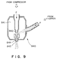
- Fig. 9 is a concept view of an example of an ejector 840 using a blowing nozzle as solid particle ejection means for ejecting solid particles together with a fluid.
- the ejector 840 shown there is an example of an ejector of the type which uses a gas as a solid particle accelerating fluid, and ejects solid particles as a mixture with the gas.
- This ejector 840 comprises a guide chamber 841 for mixing solid particles P with a fluid F, an internal nozzle 842 for injecting the fluid F into the guide chamber 841, and a blowing nozzle portion 844 for ejecting the solid particles P and the fluid F through a nozzle opening 843.
- the fluid F is fed from a compressor or fan (not shown) through a suitable pressure tank (not shown), and injected through the internal nozzle 842. Then, the fluid F is passed through the guide chamber 841, and ejected through the nozzle opening 843 of the nozzle 844.
- a negative pressure is created by the action of a stream of the fluid flowing at a high velocity. This negative pressure guides the solid particles to the fluid stream to mix the solid particles with the stream. The solid particles are accelerated and carried by the fluid stream, and ejected through the nozzle opening 843 of the nozzle 844 along with the fluid stream.
- a blowing nozzle using a liquid as a solid particle accelerating fluid is also available.
- the fluid and solid particles are mixed and stored in a pressure tank (not shown) by, for example, a pump (not shown; the fluid is liquid).
- the mixture is ejected through the nozzle opening of the blowing nozzle.
- the nozzle opening is in the shape of a hollow cylinder, a polygonal prism, a cone, a polygonal pyramid, or a fish tail.
- the blowing nozzle may be one having a single opening, or one having an inside divided like a honeycomb.
- the fluid pressure is usually about 0.1 to 100 kg/cm 2 as a spray pressure.
- the fluid stream is accelerated usually at a rate of about 1 to 80 m/sec for a liquid stream, or at a rate of about 5 to 80 m/sec for a gas stream.
- the material for the ejector such as the guide chamber or nozzle portion, may be suitably selected from ceramics, steel, titanium and titanium alloys according to the type of the fluid.
- the solid particles pass along the inner wall of the ejector.
- the material for the above parts is preferably ceramic, a material with high abrasion resistance, if rigid particles, such as metal beads or inorganic particles, are used as the solid particles.
- the fluid is a liquid, a material free from rusting, melting or corrosion is selected.
- the fluid is water, for instance, stainless steel, titanium, titanium alloy, synthetic resin, or ceramic is used. However, steel may be used, if its surface is waterproofed.
- the fluid F is used as a solid particle accelerating fluid for accelerating and carrying solid particles by its stream, and ejecting the solid particles together with the fluid from solid particle ejection means (e.g., blowing nozzle).
- the fluid F is a solid particle accelerating fluid for accelerating the solid particles.
- a gas or a liquid may be used as the fluid, but usually, a gas easy to handle is used.
- the gas is typically air, but may be carbon dioxide or nitrogen.
- the liquid is not restricted, but water is one of the preferred materials because of its incombustibility, ease of drying, nontoxicity, low price, easy of acquisition, etc.
- Other nonflammable liquid such as fluorocarbon, glycerin or silicone oil may also be used.
- the liquid (or the gas) can be impinged upon a transfer sheet together with the solid particles. Needless to say, the liquid is higher in density than the gas, so that the liquid can be accelerated more easily than the gas when the solid particles are accelerated by a stream of the fluid.
- Example 2 The inks (1) to (4) of Example 1 were mixed in equal weights to prepare a gray ink of Example 2.
- Control red and yellow inks were prepared using ordinary pigments and the same vehicle as in Example 1. (5) Red ink Watchung Red (monoazo type pigment) 5% by weight Vehicle (in accordance with red ink) (6) Yellow ink Benzidine Yellow 5G (monoazo type pigment) 10% by weight Vehicle (in accordance with red ink) 90% by weight
- the single-color inks (1) and (2) of Example 1, the gray ink of Example 2, the inks (5) and (6) of Comparative Example 1, and the gray ink of Comparative Example 2 were each printed on a transparent plasticized polyvinyl chloride sheet to use the printed sheets as samples for durability test.
- the above samples were each immersed in a 5% aqueous solution of sodium hydroxide, and exposed to outdoor sunlight for 120 hours at an average daytime atmospheric temperature of 20°C. After exposure, the samples were measured by the gray scale, and discoloration and fading compared with the samples before exposure were evaluated.
- the samples of the Examples were all at grade 4 to 5, while the samples of the Comparative Examples were all at grade 2 to 3.
- wood free paper 1 weighing 52.3 g/m 2 was melt extrusion coated with 20 ⁇ m of polypropylene as a release layer 2 to prepare a base sheet 3.
- the release layer 2 was coated with a strippable primer layer 4 consisting essentially of chlorinated rubber/acrylic resin to an amount of 3 g/m 2 . Further, a pattern layer 5 using the durable ink prepared in Example 2 was applied. Thus, a transfer sheet 10 of Example 3 having a pattern transfer layer 6 was constructed.
- the surface of a 25 mm thick porous concrete plate 8 shown in Fig. 2 was coated with a two component curable polyurethane type adhesive comprising polyether polyol and hexamethylene diisocyanate.
- a two component curable polyurethane type adhesive comprising polyether polyol and hexamethylene diisocyanate.
- an adhesive layer 7 was provided to close irregularities and holes on the surface to make a smooth surface.
- the pattern transfer layer 6 side of the transfer sheet prepared in Example 3 was superposed, and pressed with a rubber roller from the base sheet 3 side to adhere the pattern transfer layer 6.
- the composite was allowed to stand for 3 days in an atmosphere of 40°C to cure the adhesive. Then, only the base sheet 3 was peeled off to obtain a decorative concrete plate.
- the decorative concrete plate was exposed by a sunshine weatherometer under the same conditions as in Example 1. Then, its discoloration or fading was compared with the gray color after transfer. The samples tested were all visually recognized as being at grade 4 on the aforementioned gray scale.
- a print material (printed matter) formed from the gravure ink of the present invention comprising pigments and a binder with high weather resistance and high alkali resistance is excellent in durability.
- the print material can be used for an external wall or flooring of mortar from which an alkaline substance seeps and which requires weather resistance.
- a transfer sheet using this ink produces a sufficient decorative effect with durability when used on a surface of a porous concrete plate of mortar, with an adhesive selected suitably.
Landscapes
- Chemical & Material Sciences (AREA)
- Engineering & Computer Science (AREA)
- Organic Chemistry (AREA)
- Life Sciences & Earth Sciences (AREA)
- Materials Engineering (AREA)
- Wood Science & Technology (AREA)
- Chemical Kinetics & Catalysis (AREA)
- General Chemical & Material Sciences (AREA)
- Optics & Photonics (AREA)
- Physics & Mathematics (AREA)
- Structural Engineering (AREA)
- Inks, Pencil-Leads, Or Crayons (AREA)
- Laminated Bodies (AREA)
- Thermal Transfer Or Thermal Recording In General (AREA)
Applications Claiming Priority (4)
| Application Number | Priority Date | Filing Date | Title |
|---|---|---|---|
| JP24397996A JP2967515B2 (ja) | 1996-08-28 | 1996-08-28 | 耐久性グラビアインキ並びにそれを用いた化粧材及び転写シート |
| JP24397996 | 1996-08-28 | ||
| JP243979/96 | 1996-08-28 | ||
| PCT/JP1997/002999 WO1998008905A1 (fr) | 1996-08-28 | 1997-08-28 | Encre d'heliogravure durable et utilisations de celle-ci |
Publications (3)
| Publication Number | Publication Date |
|---|---|
| EP0857767A1 true EP0857767A1 (fr) | 1998-08-12 |
| EP0857767A4 EP0857767A4 (fr) | 2001-05-02 |
| EP0857767B1 EP0857767B1 (fr) | 2004-10-27 |
Family
ID=17111905
Family Applications (1)
| Application Number | Title | Priority Date | Filing Date |
|---|---|---|---|
| EP97937822A Expired - Lifetime EP0857767B1 (fr) | 1996-08-28 | 1997-08-28 | Encre d'heliogravure durable et utilisations de celle-ci |
Country Status (6)
| Country | Link |
|---|---|
| EP (1) | EP0857767B1 (fr) |
| JP (1) | JP2967515B2 (fr) |
| KR (1) | KR100301891B1 (fr) |
| DE (1) | DE69731367T2 (fr) |
| TW (2) | TW436513B (fr) |
| WO (1) | WO1998008905A1 (fr) |
Cited By (3)
| Publication number | Priority date | Publication date | Assignee | Title |
|---|---|---|---|---|
| EP1314578A1 (fr) * | 2001-11-27 | 2003-05-28 | Heineken Technical Services B.V. | Marquage à l'encre seule pour étiquettage décoratif |
| WO2020074188A1 (fr) * | 2018-10-12 | 2020-04-16 | Leonhard Kurz Stiftung & Co. Kg | Procédé pour fabriquer un corps composite minéral décoré, corps composite minéral décoré et utilisation d'une feuille multicouche |
| WO2021204503A1 (fr) * | 2020-04-08 | 2021-10-14 | Leonhard Kurz Stiftung & Co. Kg | Procédé de fabrication d'un corps composite minéral décoratif, corps composite minéral décoré et utilisation d'un film multicouche |
Families Citing this family (5)
| Publication number | Priority date | Publication date | Assignee | Title |
|---|---|---|---|---|
| KR100479636B1 (ko) * | 2002-06-29 | 2005-03-30 | 한화종합화학 주식회사 | 그라비아 인쇄용 잉크 조성물 및 이를 이용한 바닥재 |
| JP4957045B2 (ja) * | 2006-03-31 | 2012-06-20 | 東洋インキScホールディングス株式会社 | 包装用印刷インキ組成物および該組成物を用いてなる包装材料 |
| WO2012118916A2 (fr) * | 2011-03-01 | 2012-09-07 | Bayer Materialscience Ag | Procédés de fabrication automatisés pour la production de dispositifs et de films polymères déformables |
| JP2017001119A (ja) * | 2015-06-08 | 2017-01-05 | 株式会社朝日Fr研究所 | マイクロ化学チップ及びその製造方法 |
| JP7440091B2 (ja) * | 2021-02-22 | 2024-02-28 | ヤマックス株式会社 | シート |
Family Cites Families (6)
| Publication number | Priority date | Publication date | Assignee | Title |
|---|---|---|---|---|
| JPH0662886B2 (ja) * | 1986-08-20 | 1994-08-17 | 大日精化工業株式会社 | 顔料組成物 |
| JPH07106625B2 (ja) * | 1989-03-10 | 1995-11-15 | 大日本印刷株式会社 | 化粧シート |
| JPH04135826A (ja) * | 1990-09-28 | 1992-05-11 | Toppan Printing Co Ltd | 化粧板の製造方法 |
| AU693812B2 (en) * | 1993-10-25 | 1998-07-09 | Dainippon Printing Co. Ltd. | Decorative sheet |
| US5547804A (en) * | 1994-03-29 | 1996-08-20 | Dai Nippon Printing Co., Ltd. | Liquid toner, ink composition, and methods of producing the same |
| JP2987072B2 (ja) * | 1995-02-17 | 1999-12-06 | 大日精化工業株式会社 | 顔料組成物 |
-
1996
- 1996-08-28 JP JP24397996A patent/JP2967515B2/ja not_active Expired - Fee Related
-
1997
- 1997-08-28 KR KR1019980703051A patent/KR100301891B1/ko not_active Expired - Fee Related
- 1997-08-28 WO PCT/JP1997/002999 patent/WO1998008905A1/fr not_active Ceased
- 1997-08-28 EP EP97937822A patent/EP0857767B1/fr not_active Expired - Lifetime
- 1997-08-28 DE DE1997631367 patent/DE69731367T2/de not_active Expired - Lifetime
- 1997-09-04 TW TW86112773A patent/TW436513B/zh not_active IP Right Cessation
- 1997-09-04 TW TW88102973A patent/TWI227262B/zh not_active IP Right Cessation
Cited By (7)
| Publication number | Priority date | Publication date | Assignee | Title |
|---|---|---|---|---|
| EP1314578A1 (fr) * | 2001-11-27 | 2003-05-28 | Heineken Technical Services B.V. | Marquage à l'encre seule pour étiquettage décoratif |
| WO2003045705A1 (fr) * | 2001-11-27 | 2003-06-05 | Heineken Technical Services B.V. | Etiquette decorative, graphique a encre seule |
| WO2020074188A1 (fr) * | 2018-10-12 | 2020-04-16 | Leonhard Kurz Stiftung & Co. Kg | Procédé pour fabriquer un corps composite minéral décoré, corps composite minéral décoré et utilisation d'une feuille multicouche |
| TWI829773B (zh) * | 2018-10-12 | 2024-01-21 | 德商利昂哈德 庫爾茲公司 | 裝飾過的礦物複合體的製造方法、裝飾過的礦物複合體以及多層薄膜的用途 |
| US12187654B2 (en) | 2018-10-12 | 2025-01-07 | Leonhard Kurz Stiftung & Co. Kg | Method for producing a decorative mineral composite body |
| WO2021204503A1 (fr) * | 2020-04-08 | 2021-10-14 | Leonhard Kurz Stiftung & Co. Kg | Procédé de fabrication d'un corps composite minéral décoratif, corps composite minéral décoré et utilisation d'un film multicouche |
| US12600684B2 (en) | 2020-04-08 | 2026-04-14 | Leonhard Kurz Stiftung & Co. Kg | Method for producing a decorative mineral composite body |
Also Published As
| Publication number | Publication date |
|---|---|
| JPH1067956A (ja) | 1998-03-10 |
| KR100301891B1 (ko) | 2001-11-22 |
| WO1998008905A1 (fr) | 1998-03-05 |
| KR19990067109A (ko) | 1999-08-16 |
| JP2967515B2 (ja) | 1999-10-25 |
| DE69731367D1 (de) | 2004-12-02 |
| TWI227262B (en) | 2005-02-01 |
| DE69731367T2 (de) | 2006-02-09 |
| EP0857767B1 (fr) | 2004-10-27 |
| EP0857767A4 (fr) | 2001-05-02 |
| TW436513B (en) | 2001-05-28 |
Similar Documents
| Publication | Publication Date | Title |
|---|---|---|
| US6040356A (en) | Durable gravure ink and uses of the same | |
| KR100239312B1 (ko) | 삼차원성형품 그림무늬부착용 전사필름과 이를 이용한 전사방법 | |
| EP0857767B1 (fr) | Encre d'heliogravure durable et utilisations de celle-ci | |
| JP2000246859A (ja) | 化粧材 | |
| JP2005238035A (ja) | 化粧板の製造方法 | |
| JP2000001097A (ja) | 化粧材の製造方法 | |
| JP4074008B2 (ja) | 化粧材及び転写シート | |
| JPH11323263A (ja) | 転写用接着剤、それを用いた転写シートと転写方法 | |
| JP4043588B2 (ja) | 化粧板の製造方法、化粧板および絵柄転写シート | |
| JP3220849B2 (ja) | 曲面転写方法及びそれに用いる転写シート | |
| JP2000185383A (ja) | 転写シート、それを用いた転写方法、及び化粧材 | |
| JP4876305B2 (ja) | インキ組成物、転写シート、転写方法、及び化粧材 | |
| JP2001080293A (ja) | 転写シート、化粧材、及び化粧材の製造方法 | |
| JP2001129956A (ja) | 化粧材の製造方法、及び化粧材 | |
| JP2001030453A (ja) | 化粧材の製造方法 | |
| JPH11216996A (ja) | 転写シート | |
| JP2000318390A (ja) | 曲面転写装置 | |
| JP3802290B2 (ja) | 成形用転写シート及び転写方法 | |
| JP2000318111A (ja) | 化粧材の製造方法 | |
| JP2001080295A (ja) | 転写シート、及び化粧材の製造方法 | |
| JP2000263995A (ja) | 転写方法 | |
| JP2000037994A (ja) | 転写方法 | |
| JP2000218693A (ja) | 曲面転写方法及び曲面転写装置 | |
| JPH11105495A (ja) | 転写シートを用いる化粧板の製造方法 | |
| JP2001018591A (ja) | 凹凸転写用シート |
Legal Events
| Date | Code | Title | Description |
|---|---|---|---|
| PUAI | Public reference made under article 153(3) epc to a published international application that has entered the european phase |
Free format text: ORIGINAL CODE: 0009012 |
|
| 17P | Request for examination filed |
Effective date: 19980528 |
|
| AK | Designated contracting states |
Kind code of ref document: A1 Designated state(s): DE FR GB IT SE |
|
| A4 | Supplementary search report drawn up and despatched |
Effective date: 20010321 |
|
| AK | Designated contracting states |
Kind code of ref document: A4 Designated state(s): DE FR GB IT SE |
|
| 17Q | First examination report despatched |
Effective date: 20020430 |
|
| GRAP | Despatch of communication of intention to grant a patent |
Free format text: ORIGINAL CODE: EPIDOSNIGR1 |
|
| GRAS | Grant fee paid |
Free format text: ORIGINAL CODE: EPIDOSNIGR3 |
|
| GRAA | (expected) grant |
Free format text: ORIGINAL CODE: 0009210 |
|
| AK | Designated contracting states |
Kind code of ref document: B1 Designated state(s): DE FR GB IT SE |
|
| REG | Reference to a national code |
Ref country code: GB Ref legal event code: FG4D |
|
| REF | Corresponds to: |
Ref document number: 69731367 Country of ref document: DE Date of ref document: 20041202 Kind code of ref document: P |
|
| REG | Reference to a national code |
Ref country code: SE Ref legal event code: TRGR |
|
| PLBE | No opposition filed within time limit |
Free format text: ORIGINAL CODE: 0009261 |
|
| STAA | Information on the status of an ep patent application or granted ep patent |
Free format text: STATUS: NO OPPOSITION FILED WITHIN TIME LIMIT |
|
| ET | Fr: translation filed | ||
| 26N | No opposition filed |
Effective date: 20050728 |
|
| REG | Reference to a national code |
Ref country code: FR Ref legal event code: PLFP Year of fee payment: 19 |
|
| PGFP | Annual fee paid to national office [announced via postgrant information from national office to epo] |
Ref country code: FR Payment date: 20150626 Year of fee payment: 19 |
|
| PGFP | Annual fee paid to national office [announced via postgrant information from national office to epo] |
Ref country code: GB Payment date: 20150819 Year of fee payment: 19 Ref country code: DE Payment date: 20150821 Year of fee payment: 19 |
|
| PGFP | Annual fee paid to national office [announced via postgrant information from national office to epo] |
Ref country code: SE Payment date: 20150819 Year of fee payment: 19 |
|
| PGFP | Annual fee paid to national office [announced via postgrant information from national office to epo] |
Ref country code: IT Payment date: 20150824 Year of fee payment: 19 |
|
| REG | Reference to a national code |
Ref country code: DE Ref legal event code: R119 Ref document number: 69731367 Country of ref document: DE |
|
| REG | Reference to a national code |
Ref country code: SE Ref legal event code: EUG |
|
| GBPC | Gb: european patent ceased through non-payment of renewal fee |
Effective date: 20160828 |
|
| PG25 | Lapsed in a contracting state [announced via postgrant information from national office to epo] |
Ref country code: SE Free format text: LAPSE BECAUSE OF NON-PAYMENT OF DUE FEES Effective date: 20160829 |
|
| REG | Reference to a national code |
Ref country code: FR Ref legal event code: ST Effective date: 20170428 |
|
| PG25 | Lapsed in a contracting state [announced via postgrant information from national office to epo] |
Ref country code: FR Free format text: LAPSE BECAUSE OF NON-PAYMENT OF DUE FEES Effective date: 20160831 Ref country code: DE Free format text: LAPSE BECAUSE OF NON-PAYMENT OF DUE FEES Effective date: 20170301 Ref country code: GB Free format text: LAPSE BECAUSE OF NON-PAYMENT OF DUE FEES Effective date: 20160828 |
|
| PG25 | Lapsed in a contracting state [announced via postgrant information from national office to epo] |
Ref country code: IT Free format text: LAPSE BECAUSE OF NON-PAYMENT OF DUE FEES Effective date: 20160828 |