EP0858131A1 - Dispositif de couplage à deux pièces - Google Patents
Dispositif de couplage à deux pièces Download PDFInfo
- Publication number
- EP0858131A1 EP0858131A1 EP98107248A EP98107248A EP0858131A1 EP 0858131 A1 EP0858131 A1 EP 0858131A1 EP 98107248 A EP98107248 A EP 98107248A EP 98107248 A EP98107248 A EP 98107248A EP 0858131 A1 EP0858131 A1 EP 0858131A1
- Authority
- EP
- European Patent Office
- Prior art keywords
- connector
- fitting
- connector housing
- housing
- bolt
- Prior art date
- Legal status (The legal status is an assumption and is not a legal conclusion. Google has not performed a legal analysis and makes no representation as to the accuracy of the status listed.)
- Ceased
Links
Images


Classifications
-
- H—ELECTRICITY
- H01—ELECTRIC ELEMENTS
- H01R—ELECTRICALLY-CONDUCTIVE CONNECTIONS; STRUCTURAL ASSOCIATIONS OF A PLURALITY OF MUTUALLY-INSULATED ELECTRICAL CONNECTING ELEMENTS; COUPLING DEVICES; CURRENT COLLECTORS
- H01R13/00—Details of coupling devices of the kinds covered by groups H01R12/70 or H01R24/00 - H01R33/00
- H01R13/64—Means for preventing incorrect coupling
- H01R13/641—Means for preventing incorrect coupling by indicating incorrect coupling; by indicating correct or full engagement
-
- H—ELECTRICITY
- H01—ELECTRIC ELEMENTS
- H01R—ELECTRICALLY-CONDUCTIVE CONNECTIONS; STRUCTURAL ASSOCIATIONS OF A PLURALITY OF MUTUALLY-INSULATED ELECTRICAL CONNECTING ELEMENTS; COUPLING DEVICES; CURRENT COLLECTORS
- H01R13/00—Details of coupling devices of the kinds covered by groups H01R12/70 or H01R24/00 - H01R33/00
- H01R13/62—Means for facilitating engagement or disengagement of coupling parts or for holding them in engagement
- H01R13/621—Bolt, set screw or screw clamp
- H01R13/6215—Bolt, set screw or screw clamp using one or more bolts
Definitions
- This invention relates to a connector in which two connector housings are fitted together, and more particularly to a connector in which a fitting-completed condition of the two connector housings can be detected by a fitting indicator.
- the bolt tightening operation is carried out using a tool such as an impact wrench. If the bolt is tightened excessively, the bolt may be broken, or the housing may be damaged. Therefore, in recent years, there has been proposed a construction in which a threaded portion of a bolt is provided partially on a distal end portion of a bolt shaft, and in a fitting-completed condition of two connector housings, the threaded portion of the bolt extends forwardly from the nut, thereby freely rotating without engagement with the nut. This prevents excessive tightening of the bolt (for example, Japanese Patent Unexamined Publication No. 63-13283).
- the present invention has been made under the above circumstances, and an object of the invention is to provide a connector in which a fitted condition of two connector housings can be easily perceived.
- the present invention provides a connector wherein a bolt is provided on one connector housing and a nut is provided on the other connector housing. By tightening the bolt relative to the nut, the two connector housings are displaced relative to each other in a connecting direction and fitted together. An indicator is provided on the connector housing to indicate a fitting-completed condition of the two connector housing.
- the present invention according to a first embodiment provides a pressing portion provided on the one connector housing; a pressure sensitive element provided on the other connecting housing and pressed by the pressing portion in a fitting-completed condition of the two connector housings; and fitting detection connection terminals provided on the other connector housing for out-putting a signal from the pressure sensitive element.
- the present invention provides a pair of conductors provided on the connector housing and electrically connected together in a fitting-completed condition of the two connector housings; and fitting detection connection terminals provided on the connector housing for detecting whether or not electrical connection between the conductors is made.
- the pressing portion provided on the one connector housing presses the pressure sensitive element provided on the other connector housing, so that the output of the pressure sensitive element is changed. Therefore, by connecting a detection circuit to the fitting detection connection terminals to output a signal from the pressure sensitive element, the fitting-completed condition can be detected.
- the pair of conductors provided on the connector housing are electrically connected together. Therefore, by connecting the detection circuit to the fitting detection connection terminals, the fitting-completed condition of the two connector housings can be detected.
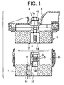
- Fig. 1 shows a condition before two connector housings 1 and 2 are fitted together
- Fig. 2 shows a fitting-completed condition of the two connector housings 1 and 2.
- a female connector housing 1 is in the form of a rectangular block as a whole and has a number of female terminals (not shown) provided therein. An upper surface portion of female connector housing 1 is covered with a cover 3 made, for example, of rubber.
- a bolt insertion hole 1a is formed through a central portion of the female connector housing 1 in a vertical direction, and a bolt 4 is received in the bolt insertion hole 1a.
- a threaded portion 4a is formed only on a distal end portion of a shaft of the bolt 4, and a bolt head 4b is projected from the upper surface of the female connector housing 1.
- the bolt 4 is rotatable relative to the female connector housing 1 and is supplied with a moving force in a direction (vertical direction in the drawings) of forward and backward threaded movement.
- the male connector housing 2 has a tubular hood portion 2b of a square shape with an open top.
- the hood portion is formed on an upper portion of a base 2a (Fig. 3), which is of a rectangular shape.
- the hood portion 2b has such a size that the female connector housing 1 can be fitted therein.
- a number of male terminals (not shown), corresponding respectively to the previously-mentioned female terminals, are provided within the male connector housing 2 and are supported on the base 2a.
- a nut 6 for threaded engagement with the bolt 4 is provided integrally within the boss 5, for example, by insert molding.
- a projection 7'' serving as a pressing portion is formed integrally on a portion of a lower surface of the female connector housing 1 slightly offset to the left of center, as best shown in Fig. 3.
- a pressure-sensitive element 17 is provided at a portion of the upper surface of the base 2a of the male connector housing 2 slightly offset to the left of center, that is, immediately adjacent to the left side of the boss 5.
- the pressure-sensitive element 17 comprises a pressure-sensitive, electrically-conductive rubber that varies in resistance upon application of pressure.
- a mounting recess 18 is formed in the upper surface of the base 2a, and a hole 19 continuous with the mounting recess 18 extends downwardly and is open to the lower surface of the male connector housing 2.
- the pressure sensitive element 17 has a generally hook-shape as viewed from a side thereof, and a pressure detection surface 17a at an upper end portion thereof is disposed in the mounting recess 18.
- a pair of fitting detection connection terminals 20 and 20 are connected at their upper ends to electrodes of the pressure-sensitive element 17.
- the terminals 20 and 20 output a signal from the pressure-sensitive element 17.
- the two connector housings 1 and 2 are fitted together in the following manner.
- the female connector housing 1 is lightly fitted in the male connector housing 2 from the upper side, so that the threaded portion 4a of the bolt 4 can be threaded into the nut 6.
- a detection circuit (not shown) is beforehand connected to the fitting detection connection terminals 20 and 20. Any one of various kinds of detection circuits can be used as such circuits are well known in the art.
- a simple circuit may include a general-purpose meter, a power source such as a battery, and a lamp or a buzzer serially connected together.
- any type may be used in so far as it can detect a change in the electrical resistance of the pressure sensitive element 17 and can indicate the change to the operator.
- the operator tightens the bolt 4 relative to the nut 6, using a tool such as an impact wrench.
- a tool such as an impact wrench.
- the two connector housings 1 and 2 are displaced relative to each other in the connecting direction to be fitted together, as described above.
- the pressure sensitive element 17 is pressed by the projection 7'', so that the electrical resistance of element 17 decreases.
- the detection circuit detects the pressing of the pressure sensitive element 17.
- the operator stops the tightening operation. Therefore, the tightening of the bolt 4 can be stopped in a suitable condition in which the fitting of the two connector housings 1 and 2 is completed without excessive or insufficient tightening of the bolt 4.
- the projection 7'' formed on the female connector housing 1 presses the pressure sensitive element 17 provided on the male connector housing 2.
- the detection circuit By detecting the output of the pressure sensitive element 17 by the detection circuit, the fitting-completed condition of the two connector housings 1 and 2 can be detected.
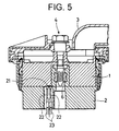
- FIG. 4 A second embodiment of the present invention will now be described with reference to Figs. 4 and 5.
- the present invention is applied to a screw tightening-type connector as in the previous embodiment.
- a metal piece 21 for electrical connection purposes is provided on a lower surface of a female connector housing 1, while a pair of conductors 22 and 22 are provided at an upper portion of a base 2a of a male connector housing 2.
- Fitting detection connection terminals 23 and 23 for determining whether or not electrical connection between the conductors 22 and 22 is established are provided within a hole in the base 2a and are connected to the conductors 22 and 22, respectively.
- a conductor and a fitting detection connection terminal may be provided on each of the two connector housings.
- the conductors provided respectively on the two connector housings can be contacted with each other in the fitting-completed condition.
- the fitting completed condition can be detected during the fitting of the two connector housings 1 and 2 or after the fitting operation.
- the pressure sensitive element 17 and the conductors 22 may be provided on the female connector housing 1.
- the pair of conductors which are electrically connected together in the fitting-completed condition are provided on the connector housing. Therefore, there is achieved an excellent advantage that by detecting whether or not electrical connection between the two conductors is established, the condition of the fitting of the two connector housings can be readily perceived.
Landscapes
- Details Of Connecting Devices For Male And Female Coupling (AREA)
Applications Claiming Priority (7)
| Application Number | Priority Date | Filing Date | Title |
|---|---|---|---|
| JP18644/93 | 1993-03-19 | ||
| JP18645/93 | 1993-03-19 | ||
| JP1864493U JPH0672177U (ja) | 1993-03-19 | 1993-03-19 | コネクタ |
| JP18646/93 | 1993-03-19 | ||
| JP1864693U JPH0672179U (ja) | 1993-03-19 | 1993-03-19 | コネクタ |
| JP1864593U JPH0672178U (ja) | 1993-03-19 | 1993-03-19 | コネクタ |
| EP94103424A EP0616392B1 (fr) | 1993-03-19 | 1994-03-07 | Dispositif de couplage à deux pièces |
Related Parent Applications (1)
| Application Number | Title | Priority Date | Filing Date |
|---|---|---|---|
| EP94103424A Division EP0616392B1 (fr) | 1993-03-19 | 1994-03-07 | Dispositif de couplage à deux pièces |
Publications (1)
| Publication Number | Publication Date |
|---|---|
| EP0858131A1 true EP0858131A1 (fr) | 1998-08-12 |
Family
ID=27282306
Family Applications (2)
| Application Number | Title | Priority Date | Filing Date |
|---|---|---|---|
| EP94103424A Expired - Lifetime EP0616392B1 (fr) | 1993-03-19 | 1994-03-07 | Dispositif de couplage à deux pièces |
| EP98107248A Ceased EP0858131A1 (fr) | 1993-03-19 | 1994-03-07 | Dispositif de couplage à deux pièces |
Family Applications Before (1)
| Application Number | Title | Priority Date | Filing Date |
|---|---|---|---|
| EP94103424A Expired - Lifetime EP0616392B1 (fr) | 1993-03-19 | 1994-03-07 | Dispositif de couplage à deux pièces |
Country Status (3)
| Country | Link |
|---|---|
| US (2) | US5486119A (fr) |
| EP (2) | EP0616392B1 (fr) |
| DE (1) | DE69411302T2 (fr) |
Cited By (2)
| Publication number | Priority date | Publication date | Assignee | Title |
|---|---|---|---|---|
| DE10026968A1 (de) * | 2000-05-31 | 2001-12-06 | Volkswagen Ag | Prüfvorrichtung |
| US10903608B1 (en) | 2019-08-27 | 2021-01-26 | International Business Machines Corporation | Multi-directional motion monitoring of plugged electrical connector |
Families Citing this family (18)
| Publication number | Priority date | Publication date | Assignee | Title |
|---|---|---|---|---|
| US5800201A (en) * | 1995-12-11 | 1998-09-01 | Sumitomo Wiring Systems, Ltd. | Connector assembly for wire harness and method for coupling the same |
| JP3189945B2 (ja) * | 1996-09-30 | 2001-07-16 | 矢崎総業株式会社 | 可動コネクタ |
| US5733152A (en) * | 1996-10-09 | 1998-03-31 | Royal Die & Stamping Co., Inc. | Battery terminal adaptor and connector |
| US5876238A (en) * | 1997-06-17 | 1999-03-02 | International Business Machines Corporation | Device and method for securing integrity of a blind autodock electrical connection |
| DE69833786T2 (de) * | 1997-12-11 | 2006-10-12 | The Furukawa Electric Co., Ltd. | Bolzenartiger verbinder |
| US5971798A (en) * | 1997-12-16 | 1999-10-26 | Sundstrand Corporation | Quick release power connector |
| ES2154240B1 (es) * | 1999-08-10 | 2001-10-16 | Mecanismos Aux Es Ind S L | Dispositivo de montaje de conectores electricos para vehiculos. |
| JP3349484B2 (ja) * | 1999-11-09 | 2002-11-25 | 住友電装株式会社 | ジョイント部の外れ検知システム |
| JP4058902B2 (ja) | 2000-12-18 | 2008-03-12 | 住友電装株式会社 | 防水コネクタ |
| DE10334071B4 (de) * | 2003-07-25 | 2005-07-07 | Siemens Ag | Steckverbindungssystem mit integrierter Verriegelung |
| US6855008B1 (en) | 2003-10-06 | 2005-02-15 | Royal Die & Stamping Co., Inc. | Fuse holder with adjustable terminals |
| US6932650B1 (en) | 2004-03-25 | 2005-08-23 | Royal Die & Stamping Co., Inc. | Fused battery terminal connector |
| US7614897B2 (en) * | 2008-02-15 | 2009-11-10 | Lear Corporation | Electrical connector system and method of assembly |
| JP5378955B2 (ja) * | 2009-11-04 | 2013-12-25 | 矢崎総業株式会社 | コネクタ構造 |
| JP5848647B2 (ja) * | 2012-03-21 | 2016-01-27 | 株式会社小松製作所 | 電動機のインターロック機構及び電動機 |
| CN103902432A (zh) * | 2012-12-29 | 2014-07-02 | 鸿富锦精密工业(深圳)有限公司 | 电子设备及其usb接口连接状况指示电路 |
| US10008789B1 (en) | 2017-07-10 | 2018-06-26 | Royal Die & Stamping, Llc | Angled bolt T-bar battery terminal clamp |
| TWI662218B (zh) * | 2018-06-04 | 2019-06-11 | 訊凱國際股份有限公司 | 連接頭組件 |
Citations (3)
| Publication number | Priority date | Publication date | Assignee | Title |
|---|---|---|---|---|
| DE2843247A1 (de) * | 1978-10-04 | 1980-04-17 | Dornier Gmbh | Elektrische steckvorrichtung |
| US5145391A (en) * | 1991-04-29 | 1992-09-08 | Gte Products Corporation | Switching connector assembly |
| US5174787A (en) * | 1990-09-14 | 1992-12-29 | Hirose Electric Co., Ltd. | Electrical connector with check terminal |
Family Cites Families (9)
| Publication number | Priority date | Publication date | Assignee | Title |
|---|---|---|---|---|
| US4015888A (en) * | 1975-11-05 | 1977-04-05 | Square D Company | Electrical device with retractable grounding pin and indicating means |
| JPS601774A (ja) * | 1983-06-17 | 1985-01-07 | 日産自動車株式会社 | ねじ締め型コネクタハウジングの嵌合表示機構 |
| FR2580434B1 (fr) * | 1985-04-12 | 1987-05-15 | Vibrachoc Sa | Dispositif de visualisation de l'enfichage d'un boitier d'equipement electronique sur un plateau d'aeronef |
| JPS63132383A (ja) * | 1986-11-21 | 1988-06-04 | Toshiba Corp | 図形処理装置における直線ストロ−ク抽出方法 |
| US4907118A (en) * | 1989-03-09 | 1990-03-06 | Curtis Manufacturing Company, Inc. | Visual indicator electrical plug-type surge protector and systems |
| JP2538693B2 (ja) * | 1990-03-23 | 1996-09-25 | 矢崎総業株式会社 | コネクタの結合検知装置 |
| US5192225A (en) * | 1990-11-08 | 1993-03-09 | Yazaki Corporation | Connector locking connection detection device |
| US5228867A (en) * | 1991-12-06 | 1993-07-20 | The Whitaker Corporation | Electrical connector bolt fastening device |
| JP2544953Y2 (ja) * | 1992-03-06 | 1997-08-20 | 日本エー・エム・ピー株式会社 | コネクタ |
-
1994
- 1994-02-18 US US08/198,282 patent/US5486119A/en not_active Expired - Lifetime
- 1994-03-07 EP EP94103424A patent/EP0616392B1/fr not_active Expired - Lifetime
- 1994-03-07 DE DE69411302T patent/DE69411302T2/de not_active Expired - Fee Related
- 1994-03-07 EP EP98107248A patent/EP0858131A1/fr not_active Ceased
-
1995
- 1995-06-07 US US08/478,783 patent/US5601450A/en not_active Expired - Fee Related
Patent Citations (3)
| Publication number | Priority date | Publication date | Assignee | Title |
|---|---|---|---|---|
| DE2843247A1 (de) * | 1978-10-04 | 1980-04-17 | Dornier Gmbh | Elektrische steckvorrichtung |
| US5174787A (en) * | 1990-09-14 | 1992-12-29 | Hirose Electric Co., Ltd. | Electrical connector with check terminal |
| US5145391A (en) * | 1991-04-29 | 1992-09-08 | Gte Products Corporation | Switching connector assembly |
Cited By (2)
| Publication number | Priority date | Publication date | Assignee | Title |
|---|---|---|---|---|
| DE10026968A1 (de) * | 2000-05-31 | 2001-12-06 | Volkswagen Ag | Prüfvorrichtung |
| US10903608B1 (en) | 2019-08-27 | 2021-01-26 | International Business Machines Corporation | Multi-directional motion monitoring of plugged electrical connector |
Also Published As
| Publication number | Publication date |
|---|---|
| EP0616392A3 (en) | 1995-09-06 |
| US5601450A (en) | 1997-02-11 |
| US5486119A (en) | 1996-01-23 |
| DE69411302D1 (de) | 1998-08-06 |
| EP0616392A2 (fr) | 1994-09-21 |
| EP0616392B1 (fr) | 1998-07-01 |
| DE69411302T2 (de) | 1999-01-28 |
Similar Documents
| Publication | Publication Date | Title |
|---|---|---|
| US5486119A (en) | Matable connector | |
| US4915649A (en) | Connector | |
| US6280229B1 (en) | Plug connector | |
| US20010027054A1 (en) | Half-fitting detection connector | |
| EP0645848A1 (fr) | Système de détection pour un connecteur enfichable | |
| EP0790673B1 (fr) | Connecteur électrique avec système de contact à détection | |
| EP0751591A3 (fr) | Connecteur de détection d'engagement | |
| EP1601054A3 (fr) | Système de connecteurs électriques | |
| US3958849A (en) | Electrical plug | |
| JP2590679Y2 (ja) | 分岐接続用コネクタ | |
| JP3264305B2 (ja) | 結合検知装置を備えたコネクタ | |
| EP1089397A3 (fr) | Connecteur électrique ayant des moyens de retenue pour la fixation détachable d' un boítier de composants | |
| EP0762556B1 (fr) | Assemblage de connecteur électrique | |
| JPH0645010A (ja) | 導線接続用電気コネクタ | |
| JP3264297B2 (ja) | コネクタの結合検知装置 | |
| JP3010237B2 (ja) | コネクタの結合確認装置 | |
| EP0926772A3 (fr) | Assemblage de connecteur électrique avec dispositif à assurer la position des terminaux | |
| EP1158619A3 (fr) | Connecteur électrique avec force de contact variable | |
| EP1009075A3 (fr) | Contact électrique et assemblage en cartouchière | |
| JPH03192669A (ja) | コネクタ | |
| US5647762A (en) | Locking structure of short-circuit contact for connectors | |
| EP0634821A2 (fr) | Douille d'ampoule | |
| JP2001159654A (ja) | コネクタ導通検査具 | |
| JP2599849Y2 (ja) | コネクタ | |
| US8357017B2 (en) | Electrical connector with improved contacts |
Legal Events
| Date | Code | Title | Description |
|---|---|---|---|
| PUAI | Public reference made under article 153(3) epc to a published international application that has entered the european phase |
Free format text: ORIGINAL CODE: 0009012 |
|
| 17P | Request for examination filed |
Effective date: 19980421 |
|
| AC | Divisional application: reference to earlier application |
Ref document number: 616392 Country of ref document: EP |
|
| AK | Designated contracting states |
Kind code of ref document: A1 Designated state(s): DE GB |
|
| RIN1 | Information on inventor provided before grant (corrected) |
Inventor name: SABA, TOSHIKAZU, C/OSUMITOMO WIRING SYSTEMS LTD. Inventor name: WATANABE, KAORU, C/OSUMITOMO WIRING SYSTEMS LTD. Inventor name: NABESHIMA, AKIRA, C/OSUMITOMO WIRING SYSTEMS LTD. |
|
| 17Q | First examination report despatched |
Effective date: 19990713 |
|
| GRAG | Despatch of communication of intention to grant |
Free format text: ORIGINAL CODE: EPIDOS AGRA |
|
| STAA | Information on the status of an ep patent application or granted ep patent |
Free format text: STATUS: THE APPLICATION HAS BEEN REFUSED |
|
| 18R | Application refused |
Effective date: 20020610 |