EP0860202B1 - Mischwerkzeug - Google Patents
Mischwerkzeug Download PDFInfo
- Publication number
- EP0860202B1 EP0860202B1 EP98102051A EP98102051A EP0860202B1 EP 0860202 B1 EP0860202 B1 EP 0860202B1 EP 98102051 A EP98102051 A EP 98102051A EP 98102051 A EP98102051 A EP 98102051A EP 0860202 B1 EP0860202 B1 EP 0860202B1
- Authority
- EP
- European Patent Office
- Prior art keywords
- mixing tool
- mixing
- shaft
- tool
- drum
- Prior art date
- Legal status (The legal status is an assumption and is not a legal conclusion. Google has not performed a legal analysis and makes no representation as to the accuracy of the status listed.)
- Expired - Lifetime
Links
Images


Classifications
-
- B—PERFORMING OPERATIONS; TRANSPORTING
- B01—PHYSICAL OR CHEMICAL PROCESSES OR APPARATUS IN GENERAL
- B01F—MIXING, e.g. DISSOLVING, EMULSIFYING OR DISPERSING
- B01F27/00—Mixers with rotary stirring devices in fixed receptacles; Kneaders
- B01F27/05—Stirrers
- B01F27/07—Stirrers characterised by their mounting on the shaft
- B01F27/072—Stirrers characterised by their mounting on the shaft characterised by the disposition of the stirrers with respect to the rotating axis
- B01F27/0726—Stirrers characterised by their mounting on the shaft characterised by the disposition of the stirrers with respect to the rotating axis having stirring elements connected to the stirrer shaft each by a single radial rod, other than open frameworks
Definitions
- the invention relates to a mixing tool for bulk materials and / or similar materials for mounting on a shaft in a drum of a mixer, dryer and / or reactor, with the features of the preamble of claim 1.
- the geometric shapes of the known mixing bodies are in general on the type of processing of the materials to be processed matched, namely whether the materials in the Pile (thrust mixer), in the mechanically generated fluidized bed (Ploughshare mixer) or in the material ring (centrifugal mixer) to be processed. Depending on the type of processing different processing times and material qualities after these processing times.
- a mixing tool is known from DE 29 42 325 C2, which a first mixing tool surface and a second mixing tool surface having. These mixing tool surfaces limit in radial direction directly to each other and extend starting from a mixer shaft up to close to the inside of the drum. With the known mixing tool, a drying Be loosened up so that it is as intense as possible Exchange to heated contact surfaces of the drum or to an elevated temperature gas stream flowing through the drum can be done.
- the mixing surfaces of the known mixing tool are wedge-shaped and with respect to their Areas not coordinated.
- the well-known mixing tools are characterized by the fact that they are from the mixer shaft starting in the radial direction, first rod-shaped are formed and in the area of the drum inner wall pass over a rod parallel to the shaft.
- DE-AS 1 101 113 is a mixing device known, the mixing tools with spaced apart Have tool surfaces. These tool surfaces (in pairs arranged centrifugal blades) move one to be machined Good in opposite directions. different Conveying directions are also defined by US 2,017,116 and FR 2.177.638 A known mixing tools achieved.
- the object of the present invention is the known Mixing tool to further develop the movements of materials to be processed in a drum seen across the drum cross-section regardless of the shaft speed both with regard to an axially directed material exchange as well as a radially oriented material exchange be improved.
- the mixing tool surfaces F 1 , F 2 are defined in cm 2 and the drum radius R is to be specified in the dimension cm.
- the mixing tool according to the invention is in an x-y-z coordinate system shown with the z-axis through the shaft runs (coincides with the shaft axis) and with the x-axis spans a floor plan (see Fig. 1 and Fig. 4 of the description).
- the y axis is perpendicular to Floor plan level, extends with positive values from this and defines the plane of motion with the x-axis of the mixing tool according to the invention.
- the tool profile surfaces F P1 and F P2 are used as further surfaces to describe the mixing tool according to the invention. These are the corresponding surfaces of a section in the xz plane through a penetration body, which is created by moving the mixing tool surfaces formed on the mixing tool through the material to be processed (rotation around the shaft).
- r P1 and r P2 indicate the distance in cm from the z-axis (shaft axis) to the centroids of the tool profile surfaces F P1 and F P2 .
- k is a constant and varies in the range from 0.3 to 1 depending on the surface distribution of the tool profile surfaces F P1 and F P2 .
- the angles ⁇ , ⁇ describe the inclinations of the tool surfaces F 1 , F 2 at an arbitrarily selected surface point in two mutually perpendicular directions.
- the angle ⁇ describes the angle between the positive y direction and the orientation of the mixing tool surface in the positive y direction in the z direction.
- the angle ⁇ denotes the angle between the positive y direction and the orientation of the mixing tool surface in the positive x direction.
- the mixing tool according to the invention has the advantage that it when rotating around the shaft with mixing tool surfaces in immerses the material to be machined, which is directed radially over the entire length of the mixing tool in the direction extend the x-axis. So that one in a drum existing material accumulation with the most varied Shaft speeds effectively processed, i.e. mixed become.
- the processing times are when mixing in the pile, mechanically generated fluidized bed and the mix ring optimized. Even at low speeds (extremely gentle on the product) unified particle movements trigger over the entire amount of material accumulation that too contribute to an improved mixing quality with a shorter mixing time.
- the mixing tool according to the invention extends from the Wave to the inner wall of the drum and holds only a small one Distance to the inside wall surface of the drum.
- the tool profile surfaces F P1 and F P2 as well as their center of gravity coordinates r P1 and r P2 are to be selected so that the material volume flow emerging from the surface F 1 is equal to or greater than k times to preferably equal to that of the material volume flow emerging from the surface F 2 .
- the angles of inclination .alpha. And .beta. Of the mixing tool surfaces F 1 and F 2 are also to be selected such that the material to be machined slides along the mixing tool surfaces and thus prevents bluffing.
- the angles of inclination ⁇ and ⁇ should be chosen such that the material mass flows emerging from the mixing tool surfaces are directed diametrically to one another and preferably axially parallel.
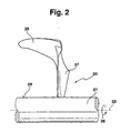
- the axial surface boundary of the first mixing tool surface F 1 ends in the z direction and the second mixing tool surface F 2 follows in the same direction without overlapping the mixing tool surfaces F 1 and F 2 in the z direction (see FIG. 2), see above the material volume flow flowing out of the mixing tool surface F 2 is not detected by the mixing tool surface F 1 .
- the material volume flows flowing into the mixing tool surface F 1 and F 2 when the mixing tool is moved are thus equal to the material volume flows flowing out from the mixing tool surfaces F 1 and F 2 .
- the material volume flow flowing out from the area F 1 is in this case equal to k times the material volume flow flowing out from the area F 2 .
- k 1, the outflowing volume flows are the same size.
- the mixing tool surfaces F 1 and F 2 are arranged such that a material volume flow flowing out of the mixing tool surface F 2 partially flows onto the mixing tool surface F 1 , then the mixing tool surfaces F 1 and F 2 can be designed according to k ⁇ 1.
- the material volume flow flowing out from the area F 1 is then greater than k times and at most equal to that of the material volume flow flowing out from the area F 2 .
- the preferred condition that the outflowing material volume flows are of the same size can be achieved, so that homogeneous mixing of the material is achieved with the shortest processing time.
- the mixing tools are distributed along the shaft over the circumference of the shaft and thus several mixing tools are provided in the drum for processing the material in the drum, these mixing tools can additionally interact with one another, so that, for example, mixing tool surfaces F 2 trigger a material direction deflection which supports the natural flow of material and the mixing tool surfaces F 1 promote the material volume flow flowing onto them against the deflection direction through the mixing tool surfaces F 2 .
- mixing tool surfaces F 2 trigger a material direction deflection which supports the natural flow of material and the mixing tool surfaces F 1 promote the material volume flow flowing onto them against the deflection direction through the mixing tool surfaces F 2 .
- embodiments are also advantageous in which at least one of the two mixing tool surfaces F 1 , F 2 differs from the Extend the shaft or a position further out close to the drum so that the mixing tool surfaces F 1 , F 2 merge into one another in the axial direction.
- the mixing tool surfaces convex and / or concavely curved.
- angles ⁇ and ⁇ at each point on the surface of the mixing tool surfaces F 1 and F 2 to be considered are constant, ie independent of location, then there are flat mixing tool surfaces.
- the mixing tool surfaces F 1 and F 2 are curved. That is, the angles ⁇ and ⁇ are different at each point on the surface of the mixing tool surfaces F 1 and F 2 to be considered (location-dependent angles).
- the so-called lead-angle must ⁇ , the angle that is not be greater between the incoming to the mixing tool faces F 1 and F 2, and of these outgoing material flow rates than a critical angle ⁇ g , which corresponds to the internal friction angle of the material to be processed. If ⁇ is larger, an additional material volume (bluff body) forms in front of the mixing tool surfaces F 1 and F 2 , which leads to an increased power consumption of the mixer. With the tool according to the invention or with the tools according to the invention, this increased power consumption is avoided and the material to be machined does not act with increased resistance on the mixing tool surfaces F 1 and F 2 .
- a mixer the shaft of which is equipped with the tools according to the invention, has drives which can set this shaft and the mixing tools attached to it in rotation.
- the speed n of the shaft is given in sec -1 .
- FIG. 1 shows a mixing tool 10 which is fastened to a shaft 11 is.
- the shaft 11 is in head pieces one not shown in the figure Drum held and rotatably supported there.
- the wave 11 has an axis 15 (axis of rotation) about which the shaft 11 can rotate in the direction of arrow 16.
- the mixing tool 10 is composed of a first mixing tool surface F 1 17 and a second mixing tool surface F 2 18.
- the mixing tool 10 is fastened to a surface 19 of the shaft 11.
- the mixing tool 10 can be screwed to the shaft 11 or welded to the shaft 11.
- a coordinate system xyz is assigned to the mixing tool 10, which is partially indicated in the figure.
- the z-axis is congruent with the axis 15 and the x-axis extends perpendicular to the z-axis in the plane of the figure.
- the y-axis extends out of the figure plane with positive values and is also arranged perpendicular to the x and z axes. If the mixing tool 10 rotates at a speed n around the shaft 11, it rotates in the plane of movement which is spanned by the coordinate axes xy.
- the mixing tool surface F 2 18 extends axially both along the negative and the positive z-axis.
- a certain material volume flow that flows out of the mixing tool surface F 2 is thus also transferred to the mixing tool surface F 1 .
- the mixing tool surface F 1 is chosen such that its axial extent decreases in the radial direction from the shaft 11 to the inner wall of the drum.
- FIG. 2 shows a further embodiment of a mixing tool 20 which is attached to a shaft 21.
- the shaft 21 has an axis 25 which can be rotated in the direction of the arrow 26.
- the mixing tool 20 is immersed in a material to be processed.
- mixing tool surfaces F 1 27 and F 2 28 move the material to be processed.
- the mixing tool surfaces F 1 27 and F 2 28 can be flat and / or curved.
- the mixing tool surface F 1 is chosen so that its axial extension increases in the radial direction from the shaft to the drum.
- the mixing tool 30 is composed of mixing tool surfaces 37, 38, the first mixing tool surface F 1 37 having an axial extent that is constant in the radial direction.
- the first mixing tool surface F 1 37 extends radially to the shaft 31 and at its end merges into the second mixing tool surface F 2 38, which in this embodiment of the mixing tool 30 extends on both sides of the first mixing tool surface F 1 37.
- the mixing tool surface F 2 38 conveys material volume flows flowing in proportion to both the mixing tool surface F 1 37 and the adjacent free space of the mixer drum and material accumulations surrounding the mixing tool.
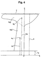
- the 4 shows a mixing tool according to the invention with tool profile surfaces F P1 and F P2 , which represent auxiliary surfaces for the mixing tool surfaces F 1 and F 2 .
- the tool profile surfaces F P1 and F P2 are surfaces which result from a cut of a penetrating body in the xz plane, the cut ending at the axis of the shaft.
- the penetrating body is created by moving the mixing tool surfaces formed on the mixing tool through the material to be processed.
- the coordinate system xyz shown in FIG. 4 runs with the z-axis through the axis of the shaft, the x-axis runs perpendicular to the z-axis and defines the plane of the figure and the y-axis extends perpendicular to both the z and the x axis and runs with positive y values out of the figure plane.
- the xy plane defines the movement plane in which a moving mixing tool rotates.
- the wave radius is indicated with r w .
- R defines the drum radius between the axis of the shaft and the inside wall of the drum.
- the mixing tool which is defined in the figure by tool profile surfaces F P1 and F P2 , is arranged between the shaft and the inner wall of the drum.
- S 1 is the centroid of the tool profile surface F P1 and S 2 is the centroid of the tool profile surface F P2 .
- r P1 and r P2 indicate the distance of the centroid S 1 and S 2 from the z-axis.
- the transition from the tool profile surface F P1 to the tool profile surface F P2 is shown in dashed lines in the drawing.
- the drum wall is identified by T.
- a mixing tool 10 for bulk goods and / or similar materials for mounting on a shaft 11 in a drum of a mixer has mixing tool surfaces F 1 17 and F 2 18 which extend radially from the shaft 11 to close to the inner wall of the mixer.
- the mixing tool surfaces F 1 17 and F 2 18 are characterized by tool profile surfaces F P1 and F P2 , which result from the fact that a cut is made through a penetrating body in the xz plane, which is produced by mixing the mixing tool surfaces F formed on the mixing tool 10 1 17 and F 2 18 moved through the material to be processed.
- the mixing tool surfaces F 1 , F 2 are designed such that, depending on the drum radius, they span surfaces limited by factors c 1 and c 2 and the material volume flows that flow back from the mixing tool surfaces F 1 17 and F 2 18 into the material to be processed are preferred are the same size and oppositely parallel to the axis.
- the mixing tool surfaces F 1 17 and F 2 18 are limited in their inclinations by angles ⁇ and ⁇ .
Landscapes
- Chemical & Material Sciences (AREA)
- Chemical Kinetics & Catalysis (AREA)
- Mixers Of The Rotary Stirring Type (AREA)
- Orthopedics, Nursing, And Contraception (AREA)
- Auxiliary Devices For Machine Tools (AREA)
- Finish Polishing, Edge Sharpening, And Grinding By Specific Grinding Devices (AREA)
Applications Claiming Priority (2)
| Application Number | Priority Date | Filing Date | Title |
|---|---|---|---|
| DE19706364 | 1997-02-19 | ||
| DE19706364A DE19706364C2 (de) | 1997-02-19 | 1997-02-19 | Mischwerkzeug |
Publications (2)
| Publication Number | Publication Date |
|---|---|
| EP0860202A1 EP0860202A1 (de) | 1998-08-26 |
| EP0860202B1 true EP0860202B1 (de) | 2003-07-02 |
Family
ID=7820708
Family Applications (1)
| Application Number | Title | Priority Date | Filing Date |
|---|---|---|---|
| EP98102051A Expired - Lifetime EP0860202B1 (de) | 1997-02-19 | 1998-02-06 | Mischwerkzeug |
Country Status (6)
| Country | Link |
|---|---|
| US (1) | US5899568A (ja) |
| EP (1) | EP0860202B1 (ja) |
| JP (1) | JP3010033B2 (ja) |
| AT (1) | ATE244059T1 (ja) |
| DE (2) | DE19706364C2 (ja) |
| ES (1) | ES2200220T3 (ja) |
Families Citing this family (23)
| Publication number | Priority date | Publication date | Assignee | Title |
|---|---|---|---|---|
| IT1310583B1 (it) * | 1999-04-30 | 2002-02-19 | Wam Spa | Dispositivo mescolatore, in particolare per materiale incoerente, ingranuli o in polvere, o pastoso. |
| CA2445074A1 (en) * | 2001-04-25 | 2002-11-14 | List Ag | Mixer bars cleaning in a radial or axial manner |
| US6805481B2 (en) * | 2001-08-31 | 2004-10-19 | Xerox Corporation | High intensity blending tool with optimized risers for increased intensity when blending toners |
| DE10321350B4 (de) * | 2003-05-13 | 2005-04-21 | Lurgi Ag | Mischvorrichtung |
| ES2325565B1 (es) * | 2007-09-24 | 2010-06-14 | Ingenieria Y Mezclas S.L. | Mezcladora de eje horizontal de palas. |
| DE102013100182A1 (de) * | 2012-09-28 | 2014-06-05 | List Holding Ag | Verfahren zur Durchführung von mechanischen, chemischen und/oder thermischen Prozessen |
| JP6109582B2 (ja) * | 2013-01-17 | 2017-04-05 | Ckd株式会社 | 液体浄化装置 |
| ITPG20130015A1 (it) * | 2013-04-15 | 2014-10-16 | Officine Galletti Omg Srl | Pala di mescolazione |
| US9867738B2 (en) | 2016-05-09 | 2018-01-16 | John J. Lenig | Ear wax remover and cleaner |
| US10328363B2 (en) * | 2016-06-09 | 2019-06-25 | Xianggen Wu | Bioreactor system and method |
| LU101612B1 (de) | 2020-01-20 | 2021-08-05 | Thyssenkrupp Ind Solutions Ag | Vorrichtung und Verfahren zur Herstellung von Zementklinker |
| WO2021148266A1 (de) | 2020-01-20 | 2021-07-29 | Thyssenkrupp Industrial Solutions Ag | Vorrichtung und verfahren zur herstellung von zementklinker |
| LU101613B1 (de) | 2020-01-20 | 2021-08-06 | Thyssenkrupp Ag | Thermische Behandlung von mineralischen Rohstoffen mit einem mechanischen Wirbelbettreaktor |
| DE102020200602A1 (de) | 2020-01-20 | 2021-07-22 | Thyssenkrupp Ag | Thermische Behandlung von mineralischen Rohstoffen mit einem mechanischen Wirbelbettreaktor |
| DE102020200604A1 (de) | 2020-01-20 | 2021-07-22 | Thyssenkrupp Ag | Vorrichtung und Verfahren zur Herstellung von Zementklinker |
| LU101611B1 (de) | 2020-01-20 | 2021-08-05 | Thyssenkrupp Ind Solutions Ag | Vorrichtung und Verfahren zur Herstellung von Zementklinker mit einem mechanischen Wirbelbettreaktor |
| DE102020200605A1 (de) | 2020-01-20 | 2021-07-22 | Thyssenkrupp Ag | Vorrichtung und Verfahren zur Herstellung von Zementklinker mit einem mechanischen Wirbelbettreaktor |
| WO2021148267A1 (de) | 2020-01-20 | 2021-07-29 | Thyssenkrupp Industrial Solutions Ag | Thermische behandlung von mineralischen rohstoffen mit einem mechanischen wirbelbettreaktor |
| EP4680583A1 (de) | 2023-03-13 | 2026-01-21 | thyssenkrupp Polysius GmbH | Zementzusatzstoff aus altbeton |
| DE102023123525A1 (de) | 2023-03-13 | 2024-09-19 | Thyssenkrupp Ag | Zementzusatzstoff aus Altbeton |
| LU103194B1 (de) | 2023-03-13 | 2024-09-13 | thyssenkrupp Polysius GmbH | Zementzusatzstoff aus Altbeton |
| WO2025113916A1 (de) | 2023-11-30 | 2025-06-05 | thyssenkrupp Polysius GmbH | Verfahren und vorrichtung zur effizienten reduktion von kohlendioxidemissionen |
| LU505664B1 (de) | 2023-11-30 | 2025-05-30 | Thyssenkrupp Ag | Verfahren und Vorrichtung zur effizienten Reduktion von Kohlendioxidemissionen |
Family Cites Families (19)
| Publication number | Priority date | Publication date | Assignee | Title |
|---|---|---|---|---|
| DE1070980B (ja) * | 1959-12-10 | |||
| US2017116A (en) * | 1932-04-02 | 1935-10-15 | Harold D Bonnell | Agitating apparatus |
| DE1101113B (de) * | 1952-03-17 | 1961-03-02 | Wilhelm Loedige | Mischeinrichtung |
| US2802650A (en) * | 1955-02-04 | 1957-08-13 | Straight Engineering Co | Pug mill knife |
| DE1082576B (de) * | 1955-03-11 | 1960-06-02 | Draiswerke Ges Mit Beschraenkt | Mischmaschine mit einem Gegenstrommischwerk |
| FR2177638A1 (ja) * | 1972-03-31 | 1973-11-09 | Gerritsen Jan | |
| IT7504823U1 (it) * | 1975-06-27 | 1976-12-27 | Mantovani Lamberto | Benna miscelatrice, applicabile in particolare su macchine o mezzi semoventi per lo scavo e/o caricamento di materiali vari |
| DE2643560C2 (de) * | 1976-09-28 | 1984-08-09 | Fa. Erwin Stelzer, 3530 Warburg | Rührvorrichtung |
| ES471554A1 (es) * | 1977-07-08 | 1979-02-16 | Loedige Maschbau Gmbh Geb | Procedimiento y dispositivo para la desecacion continua y-o granulacion de material a granel |
| DE2801460A1 (de) * | 1978-01-13 | 1979-07-19 | Loedige Maschbau Gmbh Geb | Mischmaschine mit keilfoermigen oder pflugscharartigen mischwerkzeugen |
| DE2942325A1 (de) * | 1979-10-19 | 1981-04-30 | Gebrüder Lödige Maschinenbau-Gesellschaft mbH, 4790 Paderborn | Vorrichtung zum mischen von schuettguetern |
| DE3013663C2 (de) * | 1980-04-09 | 1983-03-31 | BHS-Bayerische Berg-, Hütten- und Salzwerke AG, 8000 München | Mischarm |
| DE3034200A1 (de) * | 1980-09-11 | 1982-04-15 | Kaspar 6800 Mannheim Engels | Mischmaschine mit an mischarmen befestigten pflugscharartigen mischwerkzeugen |
| DE3344531C2 (de) * | 1983-12-09 | 1987-03-19 | Gebrüder Lödige, Maschinenbaugesellschaft mbH, 4790 Paderborn | Mischvorrichtung |
| US4650343A (en) * | 1984-11-06 | 1987-03-17 | Doom Lewis W G | Method of mixing or drying particulate material |
| DE3515318A1 (de) * | 1985-04-27 | 1986-10-30 | Draiswerke Gmbh, 6800 Mannheim | Stiftmuehle fuer mischer |
| US5061082A (en) * | 1989-11-27 | 1991-10-29 | J.C. Steele & Sons, Inc. | Replaceable pug mill blade |
| DE4344995A1 (de) * | 1993-12-30 | 1995-07-06 | Loedige Maschbau Gmbh Geb | Mischwerkzeug |
| DE19636989B4 (de) * | 1995-10-27 | 2010-08-26 | Richard Frisse Gmbh | Scher-/Mischwerkzeug |
-
1997
- 1997-02-19 DE DE19706364A patent/DE19706364C2/de not_active Expired - Fee Related
-
1998
- 1998-01-09 US US09/005,037 patent/US5899568A/en not_active Expired - Fee Related
- 1998-02-06 AT AT98102051T patent/ATE244059T1/de not_active IP Right Cessation
- 1998-02-06 ES ES98102051T patent/ES2200220T3/es not_active Expired - Lifetime
- 1998-02-06 EP EP98102051A patent/EP0860202B1/de not_active Expired - Lifetime
- 1998-02-06 DE DE59808849T patent/DE59808849D1/de not_active Expired - Fee Related
- 1998-02-19 JP JP10054528A patent/JP3010033B2/ja not_active Expired - Fee Related
Also Published As
| Publication number | Publication date |
|---|---|
| ES2200220T3 (es) | 2004-03-01 |
| DE19706364C2 (de) | 1999-06-17 |
| US5899568A (en) | 1999-05-04 |
| ATE244059T1 (de) | 2003-07-15 |
| JP3010033B2 (ja) | 2000-02-14 |
| DE59808849D1 (de) | 2003-08-07 |
| JPH10244141A (ja) | 1998-09-14 |
| EP0860202A1 (de) | 1998-08-26 |
| DE19706364A1 (de) | 1998-09-03 |
Similar Documents
| Publication | Publication Date | Title |
|---|---|---|
| EP0860202B1 (de) | Mischwerkzeug | |
| DE7834517U1 (de) | Schneckenfoerderer mit einem zwischenlager | |
| DE3344531C2 (de) | Mischvorrichtung | |
| DE2626757A1 (de) | Ruehrwerkmuehle, insbesondere kolloidmuehle | |
| EP0232531A2 (de) | Fliehkraftbearbeitungsmaschine | |
| DE69101590T2 (de) | Schüttguthebevorrichtung. | |
| DE69101830T2 (de) | Handhabungsgerät zum Bewegen eines Gegenstandes in Raum, z.B. parallel mit sichselbst. | |
| DE2364619A1 (de) | Kugelhalterung | |
| EP4218494A1 (de) | Bürstenaggregat | |
| DE7903893U1 (de) | Rotations-schleifwerkzeug | |
| DE3203223A1 (de) | Fadenliefervorrichtung fuer textilmaschinen | |
| DE2807373A1 (de) | Bodenbarbeitungsmaschine | |
| DE69105879T2 (de) | Schraubenmischer. | |
| DE69004563T2 (de) | Rotor zum Verstreuen eines teilchenförmigen Stoffes. | |
| DE1657370B2 (de) | Mischer mit einem liegenden mischtrog und auf einer welle befestigten pilzfoermigen mischfluegeln | |
| DE69607030T2 (de) | Messern für die schraubenwinde von misch- und schneidemaschinen | |
| DE1507892C3 (de) | Vorrichtung zum Benetzen pulverförmiger Stoffe mit einer Flüssigkeit | |
| DE2712933C3 (ja) | ||
| DE3304206A1 (de) | Schneidwerkzeug und halter | |
| DE1264412B (de) | Vorrichtung zur Feuchtgranulierung von pulverfoermigem Material | |
| DE1444466C (de) | Vorrichtung zum Mischen von Stoffen | |
| DE8715477U1 (de) | Mahlgerät | |
| AT259452B (de) | Vorrichtung zum Verteilen von schüttfähigem Gut | |
| DE2333032A1 (de) | Vorrichtung an putzmaschinen | |
| DE19718285A1 (de) | Putzmaschine für Gußstücke |
Legal Events
| Date | Code | Title | Description |
|---|---|---|---|
| PUAI | Public reference made under article 153(3) epc to a published international application that has entered the european phase |
Free format text: ORIGINAL CODE: 0009012 |
|
| AK | Designated contracting states |
Kind code of ref document: A1 Designated state(s): AT BE CH DE DK ES FR GB IT LI NL SE |
|
| AX | Request for extension of the european patent |
Free format text: AL;LT;LV;MK;RO;SI |
|
| 17P | Request for examination filed |
Effective date: 19981114 |
|
| AKX | Designation fees paid |
Free format text: AT BE CH DE DK ES FR GB IT LI NL SE |
|
| RBV | Designated contracting states (corrected) |
Designated state(s): AT BE CH DE DK ES FR GB IT LI NL SE |
|
| 17Q | First examination report despatched |
Effective date: 20010702 |
|
| GRAH | Despatch of communication of intention to grant a patent |
Free format text: ORIGINAL CODE: EPIDOS IGRA |
|
| GRAH | Despatch of communication of intention to grant a patent |
Free format text: ORIGINAL CODE: EPIDOS IGRA |
|
| GRAA | (expected) grant |
Free format text: ORIGINAL CODE: 0009210 |
|
| AK | Designated contracting states |
Designated state(s): AT BE CH DE DK ES FR GB IT LI NL SE |
|
| REG | Reference to a national code |
Ref country code: GB Ref legal event code: FG4D Free format text: NOT ENGLISH |
|
| REG | Reference to a national code |
Ref country code: CH Ref legal event code: EP |
|
| REF | Corresponds to: |
Ref document number: 59808849 Country of ref document: DE Date of ref document: 20030807 Kind code of ref document: P |
|
| REG | Reference to a national code |
Ref country code: CH Ref legal event code: NV Representative=s name: IPTO AG |
|
| PG25 | Lapsed in a contracting state [announced via postgrant information from national office to epo] |
Ref country code: SE Free format text: LAPSE BECAUSE OF FAILURE TO SUBMIT A TRANSLATION OF THE DESCRIPTION OR TO PAY THE FEE WITHIN THE PRESCRIBED TIME-LIMIT Effective date: 20031002 Ref country code: DK Free format text: LAPSE BECAUSE OF FAILURE TO SUBMIT A TRANSLATION OF THE DESCRIPTION OR TO PAY THE FEE WITHIN THE PRESCRIBED TIME-LIMIT Effective date: 20031002 |
|
| GBT | Gb: translation of ep patent filed (gb section 77(6)(a)/1977) |
Effective date: 20031028 |
|
| PG25 | Lapsed in a contracting state [announced via postgrant information from national office to epo] |
Ref country code: GB Free format text: LAPSE BECAUSE OF NON-PAYMENT OF DUE FEES Effective date: 20040206 Ref country code: AT Free format text: LAPSE BECAUSE OF NON-PAYMENT OF DUE FEES Effective date: 20040206 |
|
| PG25 | Lapsed in a contracting state [announced via postgrant information from national office to epo] |
Ref country code: ES Free format text: LAPSE BECAUSE OF NON-PAYMENT OF DUE FEES Effective date: 20040207 |
|
| PG25 | Lapsed in a contracting state [announced via postgrant information from national office to epo] |
Ref country code: BE Free format text: LAPSE BECAUSE OF NON-PAYMENT OF DUE FEES Effective date: 20040228 |
|
| PG25 | Lapsed in a contracting state [announced via postgrant information from national office to epo] |
Ref country code: LI Free format text: LAPSE BECAUSE OF NON-PAYMENT OF DUE FEES Effective date: 20040229 Ref country code: CH Free format text: LAPSE BECAUSE OF NON-PAYMENT OF DUE FEES Effective date: 20040229 |
|
| REG | Reference to a national code |
Ref country code: ES Ref legal event code: FG2A Ref document number: 2200220 Country of ref document: ES Kind code of ref document: T3 |
|
| ET | Fr: translation filed | ||
| PLBE | No opposition filed within time limit |
Free format text: ORIGINAL CODE: 0009261 |
|
| STAA | Information on the status of an ep patent application or granted ep patent |
Free format text: STATUS: NO OPPOSITION FILED WITHIN TIME LIMIT |
|
| 26N | No opposition filed |
Effective date: 20040405 |
|
| BERE | Be: lapsed |
Owner name: *GEBRUDER LODIGE MASCHINENBAUG.- M.B.H. Effective date: 20040228 |
|
| PG25 | Lapsed in a contracting state [announced via postgrant information from national office to epo] |
Ref country code: NL Free format text: LAPSE BECAUSE OF NON-PAYMENT OF DUE FEES Effective date: 20040901 Ref country code: DE Free format text: LAPSE BECAUSE OF NON-PAYMENT OF DUE FEES Effective date: 20040901 |
|
| GBPC | Gb: european patent ceased through non-payment of renewal fee |
Effective date: 20040206 |
|
| REG | Reference to a national code |
Ref country code: CH Ref legal event code: PL |
|
| PG25 | Lapsed in a contracting state [announced via postgrant information from national office to epo] |
Ref country code: FR Free format text: LAPSE BECAUSE OF NON-PAYMENT OF DUE FEES Effective date: 20041029 |
|
| NLV4 | Nl: lapsed or anulled due to non-payment of the annual fee |
Effective date: 20040901 |
|
| REG | Reference to a national code |
Ref country code: FR Ref legal event code: ST |
|
| PG25 | Lapsed in a contracting state [announced via postgrant information from national office to epo] |
Ref country code: IT Free format text: LAPSE BECAUSE OF NON-PAYMENT OF DUE FEES Effective date: 20050206 |
|
| REG | Reference to a national code |
Ref country code: ES Ref legal event code: FD2A Effective date: 20040207 |