EP0860217A2 - Tambour de réformation de spires de fil - Google Patents
Tambour de réformation de spires de fil Download PDFInfo
- Publication number
- EP0860217A2 EP0860217A2 EP97310638A EP97310638A EP0860217A2 EP 0860217 A2 EP0860217 A2 EP 0860217A2 EP 97310638 A EP97310638 A EP 97310638A EP 97310638 A EP97310638 A EP 97310638A EP 0860217 A2 EP0860217 A2 EP 0860217A2
- Authority
- EP
- European Patent Office
- Prior art keywords
- reforming chamber
- coil
- stem
- intercepting
- carrier
- Prior art date
- Legal status (The legal status is an assumption and is not a legal conclusion. Google has not performed a legal analysis and makes no representation as to the accuracy of the status listed.)
- Withdrawn
Links
Images




Classifications
-
- B—PERFORMING OPERATIONS; TRANSPORTING
- B21—MECHANICAL METAL-WORKING WITHOUT ESSENTIALLY REMOVING MATERIAL; PUNCHING METAL
- B21C—MANUFACTURE OF METAL SHEETS, WIRE, RODS, TUBES, PROFILES OR LIKE SEMI-MANUFACTURED PRODUCTS OTHERWISE THAN BY ROLLING; AUXILIARY OPERATIONS USED IN CONNECTION WITH METAL-WORKING WITHOUT ESSENTIALLY REMOVING MATERIAL
- B21C47/00—Winding-up, coiling or winding-off metal wire, metal band or other flexible metal material characterised by features relevant to metal processing only
- B21C47/02—Winding-up or coiling
- B21C47/10—Winding-up or coiling by means of a moving guide
- B21C47/14—Winding-up or coiling by means of a moving guide by means of a rotating guide, e.g. laying the material around a stationary reel or drum
Definitions
- This invention relates generally to rolling mills where hot rolled steel rod is formed into rings which are subjected to thermal processing while arranged in an overlapping non-concentric pattern on a conveyor, and is concerned in particular with an improvement in the reforming chamber which receives the rings from the delivery end of the conveyor and gathers them into cylindrical coils.
- an entire billet length of the rod can either be formed in a single large coil, or the rod can be subdivided into two half weight coils. This subdivision is usually effected by a complicated shear mechanism located in the reforming chamber. Such shear mechanisms are prone to malfunction, are difficult to maintain, and the resulting cuts often produce sharp ends which can create a safety hazard.
- the present invention avoids the aforementioned problems by eliminating the shear mechanism in the reforming chamber, and substituting in its place a much simpler arrangement for physically separating the coil into half weight segments connected by a readily accessible strand which can be severed outside the reforming chamber.
- the invention relates to a reforming chamber for a rolling mill wherein the chamber is positioned to receive rings descending along a vertical path from a delivery end of a conveyor onto an underlying carrier, wherein the carrier has an upstanding stem around which rings accumulate to form a cylindrical coil and wherein a first interceptor member operates above the carrier to interrupt the descent of rings, and a second interceptor member supported beneath the first interceptor member operates to divided the coil being formed around the stem into upper and lower segments, with a gap therebetween occupied by the second interceptor member.
- the delivery end of a rolling mill comprising a finishing block 10 having multiple pairs of work rolls offset one from the other by 900 to produce a hot rolled steel rod 12.
- the rod is quenched in one or more water boxes 14 before being directed by driven pinch rolls 16 to a laying head 18.
- the laying head forms the rod into a series of rings 20 which are received in an overlapping non-concentric pattern on a roller conveyor 22.
- the rings are subjected to thermal processing which typically involves controlled cooling on the conveyor before being delivered to a reforming station generally indicated at 24. At the reforming station, the rings are gathered into cylindrical coils.
- the rings 20 descend from the delivery end of the conveyor 22 along a vertical path "P" bounded by a cylindrical chamber wall 26.
- a centrally disposed mandrel 28 provides initial guidance for the descending rings.
- the mandrel is supported on first intercepting members 30.
- the first intercepting members are adjusted by first operating means, herein depicted as piston-cylinder units 32, between operative positions as shown protruding through the chamber wall 26 into the path of ring descent, and retracted positions clear of the path of ring descent.
- first operating means herein depicted as piston-cylinder units 32
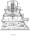
- a carrier generally indicated at 36 is located beneath the chamber 26.
- the carrier includes a pallet 38 defining a coil support surface 40, and a stem 42 protruding vertically from the pallet in axial alignment with the mandrel 28.
- the carrier is movable into and out of its position beneath the reforming chamber 28 on the rollers 44 of a conventional conveyor.
- the carrier 36 is supported on the conveyor rollers 44, as shown in Figure 2, the upper end of the stem 42 is spaced beneath the bottom end of the mandrel 28.
- the mandrel 28 is in turn supported by the first intercepting members 30.
- a coil plate 46 is carried on an elevator 48, the latter being guided for movement along vertical supports 50.
- the elevator is raised and lowered in a conventional manner by a system of chains 52 and sprockets 54.
- the coil plate is subdivided into two segments 46a, 46b which are pivotally attached as at 56 to the elevator 48.
- Piston-cylinder units 58 are employed to pivotally adjust the coil plate segments 46a, 46b between closed positions surrounding the stem 42 as shown by the solid lines in Figure 3, and open positions indicated by the broken lines in the same view.
- the stem 42 carries second intercepting members in the form of arms 60 having laterally extending lingers 62.
- the lowers ends of the arms 60 terminate in collars 64 rotatably supported on pins 66.
- the collars 64 have radially extending crank arms 68 which are connected as at 70 to a sleeve 72 having a depending stem 74.
- the sleeve is biased downwardly by a coiled spring 76, thereby urging the arms 60 into positions inwardly inclined towards the central axis of the stem 42, as shown in Figure 2, with the lingers 62 being inwardly withdrawn within the cross sectional profile of the stem.
- An elevator platform 78 is arranged beneath and provides support for the conveyor rollers 44 at the reforming station.
- the elevator platform carries a second operating means in the form of a piston-cylinder unit 80, and is vertically adjustable by any known mechanism, for example a conventional scissor jack arrangement generally depicted at 82.
- the carrier 36 is supported on the conveyor rollers 44, with the elevator platform 78 in a lowered position.
- the upper end of the stem 42 is spaced beneath the mandrel 28, the latter being supported on the intercepting members 30 with rings temporarily being accumulated thereon around the mandrel and within the chamber wall 26.
- the coil plate 46 has been elevated to a position closely underlying the intercepting members 30.
- the scissor jack 82 is then operated to raise the pallet 38, thereby placing the upper end of the stem 42 in contact with the lower end of the mandrel 28.
- the mandrel is now supported on the stem, clearing the way for retraction of the intercepting members 30, and thereby allowing a coil to continue accumulating on the coil plate 46.
- the coil plate 46 is gradually lowered to accommodate the growing height of the coil. This continues until a half coil C1, has been accumulated on the coil plate. At this juncture, the intercepting members 30 are again advanced into the path of ring descent to interrupt further accumulation of rings therebeneath.
- the coil plate 46 is dropped to its lowermost position and its two half segments 46a, 46b are opened to deposit the half coil C1 on the underlying pallet 38.
- the coil plate 46 is then returned to its raised position, where it is again closed, afier which the intercepting members are 30 retracted to allow the second half of the coil C 2 to begin accumulating on the coil plate.
- the piston-cylinder unit 80 of the second operating means is actuated to raise the stem 74 against the biasing force of the spring 76, thereby pivoting the arms 60 to operative positions extending substantially parallel to the central axis of the stem, with the fingers 62 now protruding radially outwardly beyond the cross-sectional profile of the stem 42.
- the coil plate 46 is again gradually lowered to accommodate formation of the second coil half C 2 .
- the intercepting members 30 are again advanced into the path of ring descent, and the coil plate 46 is lowered further to deposit the second half of the coil C 2 on the radially outwardly protruding fingers 62.
- the fingers 62 establish a physical separation between the two coil halves C 1 ,C 2 , with the only connection therebetween being a single readily accessible strand 82.
- the piston-cylinder unit 80 is then deactivated.
- the stem 74 remains raised against the biasing action of the spring 76 due to the weight of the upper coil segment bearing down on the radially extended fingers 62.
- the scissor jack 82 is then actuated to lower the elevator platform 78.
- the stem 42 drops with the pallet, thereby transferring support of the mandrel 28 back to the intercepting members 30.
- the coil plate 46 is returned to its uppermost position in preparation for receipt to the next coil half.
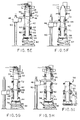
- the loaded carrier 36 is then transferred away from the coil forming station to a remote location where the connecting strand 82 can be severed by any conventional means, one example being a manually operated shear. From here, the loaded carrier is moved along the conveyor to a downending station depicted in Figure 5J.
- the downending station includes a short roller table section 84 mounted for rotatable movement about an axis 86.
- the carrier pallet 38 is held down on the roller table section 84 by powered or stationary clamps 88, and a piston cylinder unit 90 similar to unit 80 at the reforming station 24 acts against the stem 74 of the carrier to insure that the arms 60 remain operatively positioned with the fingers 62 positioned between the two half coil segments C 1 ,C 2 , on the stem 42.
- a piston-cylinder unit 92 then acts to rotate the roller table section 84 about axis 86 to the position indicated by the broken lines, thereby placing the stem 42 in a horizontal attitude.
- Coil half C 2 is removed by any convenient means (not shown), after which the piston cylinder unit 90 is deactivated, allowing the arms 60 to collapse inwardly under the force of spring 76. This retracts fingers 62, clearing the way for removal of coil half C 1 . Thereafter, the roller table section 84 is returned to its original position, and the clamps 88 are released, thereby freeing the carrier to continue along the conveyor back to the reforming station.
- the present invention achieves a marked simplification in the design of the reforming chamber.
- Complicated shears and associated strand locating devices are eliminated in favour of a simple coil dividing and separating mechanism forming part of the coil carrier.
- the single strand connecting the physically separated coil halves is readily accessible by operating personnel at a location remote from the reforming station.
Landscapes
- Engineering & Computer Science (AREA)
- Mechanical Engineering (AREA)
- Winding, Rewinding, Material Storage Devices (AREA)
- Pallets (AREA)
- Catalysts (AREA)
Applications Claiming Priority (2)
| Application Number | Priority Date | Filing Date | Title |
|---|---|---|---|
| US787579 | 1997-01-22 | ||
| US08/787,579 US5735477A (en) | 1997-01-22 | 1997-01-22 | Stem coil pallet for making half weight coils |
Publications (2)
| Publication Number | Publication Date |
|---|---|
| EP0860217A2 true EP0860217A2 (fr) | 1998-08-26 |
| EP0860217A3 EP0860217A3 (fr) | 2000-06-21 |
Family
ID=25141938
Family Applications (1)
| Application Number | Title | Priority Date | Filing Date |
|---|---|---|---|
| EP97310638A Withdrawn EP0860217A3 (fr) | 1997-01-22 | 1997-12-29 | Tambour de réformation de spires de fil |
Country Status (6)
| Country | Link |
|---|---|
| US (1) | US5735477A (fr) |
| EP (1) | EP0860217A3 (fr) |
| CN (1) | CN1066648C (fr) |
| BR (1) | BR9800433A (fr) |
| CA (1) | CA2222353C (fr) |
| TW (1) | TW347352B (fr) |
Cited By (1)
| Publication number | Priority date | Publication date | Assignee | Title |
|---|---|---|---|---|
| WO2022150440A1 (fr) * | 2021-01-11 | 2022-07-14 | Primetals Technologies USA LLC | Systèmes automatisés de découpe de bobine de fil-machine et procédé correspondant |
Families Citing this family (9)
| Publication number | Priority date | Publication date | Assignee | Title |
|---|---|---|---|---|
| US6073873A (en) * | 1997-11-14 | 2000-06-13 | Morgan Construction Company | Coil forming apparatus and method |
| RU2203756C2 (ru) * | 1998-10-30 | 2003-05-10 | Морган Констракшн Компани | Охладительный контейнер с вертикально перемещаемой платформой для бунта |
| US7823431B2 (en) * | 2003-06-13 | 2010-11-02 | Siemens Industry, Inc. | Method and apparatus for temporarily interrupting the passage of long products between upstream and downstream paths in a rolling mill |
| US8388297B2 (en) * | 2010-01-27 | 2013-03-05 | Siemens Industry, Inc. | Coil downender |
| US8540070B2 (en) * | 2011-07-19 | 2013-09-24 | Siemens Industry, Inc. | Coil shift transfer car |
| US9162269B2 (en) * | 2012-11-29 | 2015-10-20 | Primetals Technologies USA LLC | Coil forming apparatus and method |
| CN103433306B (zh) * | 2013-08-21 | 2016-05-25 | 中冶赛迪工程技术股份有限公司 | 双托臂集卷装置 |
| US10087003B2 (en) * | 2015-09-10 | 2018-10-02 | Primetals Technologies USA LLC | Direct coil transfer system |
| CN118289583A (zh) * | 2024-04-12 | 2024-07-05 | 本溪北营钢铁(集团)股份有限公司 | 一种高速线材集卷装置及方法 |
Family Cites Families (9)
| Publication number | Priority date | Publication date | Assignee | Title |
|---|---|---|---|---|
| US553353A (en) * | 1896-01-21 | Machine | ||
| US3088690A (en) * | 1959-06-02 | 1963-05-07 | Delore Sa Geoffroy | Wire coiling apparatus |
| US3054570A (en) * | 1960-12-15 | 1962-09-18 | Vaughn Machinery Co | Wire packaging machine |
| US3618871A (en) * | 1969-08-01 | 1971-11-09 | Morgan Construction Co | Rod-intercepting means in a coil-forming chamber |
| US4451198A (en) * | 1978-07-17 | 1984-05-29 | Sanderson Edward T | Material handling device |
| US4251037A (en) * | 1979-11-13 | 1981-02-17 | Morgan Construction Company | Coil forming apparatus with axially adjustable mandrels |
| JPS57170352A (en) * | 1981-04-13 | 1982-10-20 | Nippon Steel Corp | Method and apparatus for bundling ring-shaped wire rod |
| DD203890A1 (de) * | 1982-03-18 | 1983-11-09 | Norbert Brennecke | Dornpalette zum sammeln von drahtwindungen |
| US5501410A (en) * | 1995-01-27 | 1996-03-26 | Morgan Construction Company | Coil reforming chamber with auxiliary coil plate |
-
1997
- 1997-01-22 US US08/787,579 patent/US5735477A/en not_active Expired - Fee Related
- 1997-11-27 CA CA002222353A patent/CA2222353C/fr not_active Expired - Fee Related
- 1997-12-01 TW TW086118037A patent/TW347352B/zh active
- 1997-12-15 CN CN97109494A patent/CN1066648C/zh not_active Expired - Fee Related
- 1997-12-29 EP EP97310638A patent/EP0860217A3/fr not_active Withdrawn
-
1998
- 1998-01-22 BR BR9800433A patent/BR9800433A/pt not_active Application Discontinuation
Cited By (2)
| Publication number | Priority date | Publication date | Assignee | Title |
|---|---|---|---|---|
| WO2022150440A1 (fr) * | 2021-01-11 | 2022-07-14 | Primetals Technologies USA LLC | Systèmes automatisés de découpe de bobine de fil-machine et procédé correspondant |
| US12569900B2 (en) | 2021-01-11 | 2026-03-10 | Primetals Technologies USA LLC | Automated rod coil cutting station |
Also Published As
| Publication number | Publication date |
|---|---|
| CA2222353C (fr) | 2001-08-28 |
| US5735477A (en) | 1998-04-07 |
| TW347352B (en) | 1998-12-11 |
| CA2222353A1 (fr) | 1998-07-22 |
| BR9800433A (pt) | 1999-07-20 |
| EP0860217A3 (fr) | 2000-06-21 |
| CN1066648C (zh) | 2001-06-06 |
| CN1188692A (zh) | 1998-07-29 |
Similar Documents
| Publication | Publication Date | Title |
|---|---|---|
| US5735477A (en) | Stem coil pallet for making half weight coils | |
| AU733149B2 (en) | Coiling machine for hot rolled stock such as strip or sheet | |
| US20190084023A1 (en) | Reform tub iris to also include coil shear | |
| US4011780A (en) | Apparatus for trimming and/or subdividing mill product at a coil forming station | |
| EP0916422B1 (fr) | Procédé et dispositif de formation de boucles | |
| EP0723825B1 (fr) | Tambour de reformage de bobines avec plateau auxiliaire | |
| US3360842A (en) | Apparatus for collecting and dividing rod into bundles | |
| US5318276A (en) | Apparatus for conveying rolled stock wound into coils in the reeling installation area | |
| US3968671A (en) | Cooling bed method | |
| US4807457A (en) | Line to cool wound bundles of rolled wire and rod | |
| EP2925465B1 (fr) | Appareil et procédé de formation d'enroulement | |
| MXPA98000648A (en) | Rolled load platform with vastago to make rolls of half of p | |
| US2991023A (en) | Apparatus for handling coils of strip material | |
| US3123236A (en) | Apparatus for transferring coils of metallic strip | |
| EP0049621A2 (fr) | Séparation des bâtons ou barres dans des laminoirs | |
| EP1126936B1 (fr) | Dispositif pour retirer des bobines de materiau lamine d'une machine de bobinage correspondante | |
| US3850204A (en) | Product handling apparatus | |
| CN121752372A (zh) | 卷筒成形机和用于形成卷筒的对应方法 | |
| JPS6227288Y2 (fr) | ||
| HU180063B (en) | Device for dataching coil from coil set | |
| US1491566A (en) | Coiling machine | |
| KR100543303B1 (ko) | 코일형 스크랩 제거장치 |
Legal Events
| Date | Code | Title | Description |
|---|---|---|---|
| PUAI | Public reference made under article 153(3) epc to a published international application that has entered the european phase |
Free format text: ORIGINAL CODE: 0009012 |
|
| AK | Designated contracting states |
Kind code of ref document: A2 Designated state(s): DE ES FR GB IT |
|
| AX | Request for extension of the european patent |
Free format text: AL;LT;LV;MK;RO;SI |
|
| PUAL | Search report despatched |
Free format text: ORIGINAL CODE: 0009013 |
|
| AK | Designated contracting states |
Kind code of ref document: A3 Designated state(s): AT BE CH DE DK ES FI FR GB GR IE IT LI LU MC NL PT SE |
|
| AX | Request for extension of the european patent |
Free format text: AL;LT;LV;MK;RO;SI |
|
| RIC1 | Information provided on ipc code assigned before grant |
Free format text: 7B 21C 47/14 A, 7B 21C 47/24 B |
|
| 17P | Request for examination filed |
Effective date: 20000706 |
|
| AKX | Designation fees paid |
Free format text: DE ES FR GB IT |
|
| 17Q | First examination report despatched |
Effective date: 20020206 |
|
| STAA | Information on the status of an ep patent application or granted ep patent |
Free format text: STATUS: THE APPLICATION IS DEEMED TO BE WITHDRAWN |
|
| 18D | Application deemed to be withdrawn |
Effective date: 20020817 |