EP0860703A2 - Dispositif de contrÔle de la continuité du type à verrouillage automatique - Google Patents
Dispositif de contrÔle de la continuité du type à verrouillage automatique Download PDFInfo
- Publication number
- EP0860703A2 EP0860703A2 EP98301184A EP98301184A EP0860703A2 EP 0860703 A2 EP0860703 A2 EP 0860703A2 EP 98301184 A EP98301184 A EP 98301184A EP 98301184 A EP98301184 A EP 98301184A EP 0860703 A2 EP0860703 A2 EP 0860703A2
- Authority
- EP
- European Patent Office
- Prior art keywords
- receiving member
- connector
- connector housing
- test area
- connector receiving
- Prior art date
- Legal status (The legal status is an assumption and is not a legal conclusion. Google has not performed a legal analysis and makes no representation as to the accuracy of the status listed.)
- Withdrawn
Links
- 238000012360 testing method Methods 0.000 claims abstract description 165
- 230000007246 mechanism Effects 0.000 claims abstract description 91
- 238000003780 insertion Methods 0.000 claims abstract description 44
- 230000037431 insertion Effects 0.000 claims abstract description 44
- 239000000523 sample Substances 0.000 claims description 27
- 230000004044 response Effects 0.000 claims description 3
- 238000010998 test method Methods 0.000 claims 3
- 230000006835 compression Effects 0.000 description 20
- 238000007906 compression Methods 0.000 description 20
- 230000008901 benefit Effects 0.000 description 9
- 239000004020 conductor Substances 0.000 description 3
- 238000010586 diagram Methods 0.000 description 3
- 238000000605 extraction Methods 0.000 description 3
- 239000011347 resin Substances 0.000 description 3
- 229920005989 resin Polymers 0.000 description 3
- 230000000717 retained effect Effects 0.000 description 3
- 239000000284 extract Substances 0.000 description 2
- 230000009471 action Effects 0.000 description 1
- 238000000429 assembly Methods 0.000 description 1
- 230000007547 defect Effects 0.000 description 1
- 230000002950 deficient Effects 0.000 description 1
- 230000000994 depressogenic effect Effects 0.000 description 1
- 238000001514 detection method Methods 0.000 description 1
- 230000000694 effects Effects 0.000 description 1
- 239000013013 elastic material Substances 0.000 description 1
- 238000009429 electrical wiring Methods 0.000 description 1
- 230000006872 improvement Effects 0.000 description 1
- 239000012774 insulation material Substances 0.000 description 1
- 239000000463 material Substances 0.000 description 1
- 238000000465 moulding Methods 0.000 description 1
Images


Classifications
-
- G—PHYSICS
- G01—MEASURING; TESTING
- G01R—MEASURING ELECTRIC VARIABLES; MEASURING MAGNETIC VARIABLES
- G01R31/00—Arrangements for testing electric properties; Arrangements for locating electric faults; Arrangements for electrical testing characterised by what is being tested not provided for elsewhere
- G01R31/50—Testing of electric apparatus, lines, cables or components for short-circuits, continuity, leakage current or incorrect line connections
- G01R31/66—Testing of connections, e.g. of plugs or non-disconnectable joints
- G01R31/68—Testing of releasable connections, e.g. of terminals mounted on a printed circuit board
- G01R31/69—Testing of releasable connections, e.g. of terminals mounted on a printed circuit board of terminals at the end of a cable or a wire harness; of plugs; of sockets, e.g. wall sockets or power sockets in appliances
Definitions
- the present invention relates to an auto-lock style continuity test unit, and more specifically relates to continuity testing for automobile wire harnesses, testing of sub-assemblies (hereinafter referred to as "wire assembly") including a wire harness, or testing between electrical devices.
- wire assembly sub-assemblies
- the wire assembly is, in general, an electrical wiring system which forms a predetermined circuit in connection with a plurality of wires.
- Terminal fittings which include a male or female type connected with each electric wire, are incorporated in a connector housing, and are protected by a so-called lance type non-slip element.
- lance type non-slip element By connecting a connector housing which incorporate a male terminal fitting with one which incorporates a female terminal fitting, electrical connection is achieved between both terminal fittings.
- the terminal fittings mentioned above are not permitted to slip off from the connector housing with the external force normally applied during use or to encounter a nonconductive failure.
- continuity test units have conventionally been proposed to test the electrical continuity or mechanical standstill condition of terminal fittings incorporated in the connector housing.
- the continuity test units heretofore proposed have been provided with a housing holder which retains a connector housing, and a test device which carries probe pins to contact the terminal fittings in the retained connector housing.
- a so-called 2 probe-form which has a switch function and is well known in the art
- the above-mentioned housing holder and test device are mutually constructed so as to be relatively movable, and the probe pins are brought into contact with the terminal fittings by relatively moving the housing holder and check device using a manual lever, such as a toggle lever.
- the structure comprises a connector insertion area for inserting a connector housing to be checked, probe pins mounted inside the connector insertion area, and a connecting tool for connecting the back of the inserted connector, and is arranged to allow the connector to fasten to the connector insertion area by shifting the above-mentioned connecting tool in a direction across the axial direction of the connector at a certain time.
- the present invention was made to overcome the above-mentioned inconvenience, and the object is to provide an auto-lock type continuity test unit not limited to a few probe pins.
- the present invention is directed to an auto-lock type continuity test unit which is provided with a connector receiving member into which a connector housing, which becomes a test object, can be inserted.
- a test area is provided which contains probe pins for continuity testing of test terminal fittings of a connector housing inserted into a connector receiving member, and a connecting mechanism is provided to fasten the corresponding connector housing in such a manner capable of testing the continuity against the test area with a connector receiving member being shiftable both to a connected state that connects with the back of the connector housing inserted in the connector receiving member and a released state that permits removal of the connector housing from the connector receiving member.
- a driving mechanism is provided to relatively shift a connector receiving member and test area between an engaged state and a separated state by moving a connector receiving member and a test area to an engaged state in which the test area engages in a continuity testing manner and to a separated state away from the connector housing.
- a control mechanism is provided to control the driving mechanism so that the connector receiving member and the test area move relatively from a separated state at a predetermined time by shifting the connector receiving member relative to the test area to the engaged state as a result of insertion of the connector housing into the connector receiving member.
- the present invention which contains this particular item, when a worker inserts a connector housing into a connector receiving member, insertion of the connector housing can be made without interference between probe pins of the test area and terminal fittings of the connector housing by relatively shifting a connector receiving member and a test area to a separated state.
- the control mechanism since the control mechanism relatively shifts the connector receiving member and test area, the test area engages the retained connector housing and carries out a predetermined continuity test.
- the control mechanism again controls the driving mechanism, and then relatively returns the connector receiving member and check area. Therefore, the worker can easily remove the connector housing from the connector receiving member.
- any structure in which either one is fixed while the other shifted, or both are shifted, may be provided.
- an interlocking mechanism for interlocking the connecting mechanism with the driving mechanism is provided so that the connector housing is locked in the connector receiving member at least when testing, with the connecting mechanism shifted between a connected state and a released state by interlocking with the relative movement between the connector receiving member and the test area.
- an opening and closing action of the connecting mechanism is achieved by interlocking the relative movement between the connector receiving member and the test area by a driving mechanism.
- a link member is included which links the connecting mechanism to the test area so that inserting the connector housing into a connector receiving member is made by maintaining the connecting mechanism in the released state at an initial condition.
- the interlocking mechanism includes a link member which links a connecting mechanism with a testing device so that the connecting mechanism is maintained in a connected state in an initial condition and also the connecting mechanism is allowed to be pushed into a released state by a connector housing to be inserted into the connector receiving member, and a driving mechanism for interlocking capable of driving the link member independently from the driving mechanism.
- the connecting mechanism since the connecting mechanism is maintained in a connected state in an initial condition, a worker inserts a connector housing into a connector receiving member by pushing and widening a connecting mechanism from a connected state to a released state. Therefore, the connecting mechanism cannot shift from a widened state to the connected state unless the connector housing is completely inserted into the connector receiving member.
- the link member in another embodiment is provided in a relatively shiftable manner to the test area, so that the connecting mechanism permits shift to a released state when the test area is in a separated state and also the connecting mechanism controls the shift to a released state when the test area is in an engaged state.
- relatively shifting the link member to the test area allows the connector housing to be detached by shifting the connecting mechanism to a released state in an initial condition.
- the connecting mechanism is controlled to shift to a release state, which protects the connector housing from being inadvertently removed from the connector receiving member.
- Another embodiment of the present invention is provided with an elastic body capable of controlling the connector housing in a removal direction which is inserted into the connector receiving member.
- the present invention which includes this specific feature can eject the connector housing from the connector receiving member by the elastic body.
- This elastic body by being provided in the connector receiving member, is structured in a relatively shiftable manner to the test area. Therefore, the contact force by the elastic body can be set to a sufficient level to exclusively eject the connector housing.
- a connector housing when a connector housing is inserted into a connector receiving member by a worker, insertion of the connector housing is made possible without interference between the probe pins in the test area and the terminal fittings of the connector housing, thus making it possible for the connector housing to be inserted into the connector receiving member without regard to the type of probe pins. Therefore, according to the present invention, either 1 probe-form (which does not have a switch function and which is also well known in the art) style or 2 probe-form style can be easily adopted, thereby achieving remarkable results for minimizing the limitation of probe pins.
- the connecting mechanism allows the insertion of the connector housing onto a connector receiving member by maintaining the connecting mechanism at a released state in the initial condition, there is the advantage of improving the workability because of the capability for easy insertion of the connector housing into the connector receiving member.
- the interlocking mechanism contains an interlocking drive mechanism or the like, because it becomes difficult to shift the connecting mechanism to a connected state, unless the connector housing is completely inserted into the connector receiving member, the worker cannot confirm the shift of the connecting mechanism visually or by actual touch, i.e., whether or not the connector housing is completely inserted into the connector receiving member.
- the link member allows the connecting mechanism to be shifted to a released state in case the test area is in a separated state, while when the test area is in an engaging state, as if by controlling the shift of the connecting mechanism to a released state, and when the link member is provided to the test area in a relatively shiftable manner, the connector housing can easily be detached when a safety level is assumed and stays constant, thereby providing an advantage of both safety and workability.
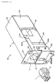
- An auto-lock type continuity test unit 10 in the illustrated embodiment is provided with a connector insertion area or connector receiving member 20 and test area 30 on an external plate 11 which forms an outside housing and which is recessed in an exterior plate of a test board (not illustrated) .
- the above-mentioned outside plate 11 integrally forms a main body 12 which is bent in a substantial U-shape and has mounting flanges 13 formed on opposite sides of the main body 12.
- the main body 12 is housed within an aperture (as shown in phantom by vertical line h in Figures 1 and 2) formed in the above-mentioned exterior plate of the test board, by fitting this flange area 13 on the above-mentioned exterior plate, and also fitting the flange area 13 on the above-mentioned exterior plate by use of small screws, the structure is made in such a way that the connector receiving member 20 is arranged on the surface, with the remainder of the test unit 10 being concealed beneath the exterior plate.
- the above-mentioned connector receiving member 20 may be formed by a resin molding which is attached to the main body 12 of the outer plate 11 (by the use of small screws).
- One side of the connector receiving member 20 includes an insertion opening 21 positioned for receiving the connector housing 1 which is to be a tested object.
- the insertion opening 21 has a depth substantially equal to the longitudinal dimension of the connector housing so that the connector housing 1 is substantially entirely received within the insertion opening 21.
- the connector housing 1 when fully inserted within recess opening 21, has its rear surface positioned substantially flush with the outer surface of the connector receiving member 20 having the insertion opening 21 as seen in Figure 4(B).
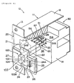
- an upper step area 22 is offset from the outer surface of the connector receiving member 20 which forms the insertion opening 21.
- a groove 23 is provided, the inner surface of which is at the same level as the outer surface of the insertion opening 21.
- the groove 23 extends in the vertical direction as seen in the drawing, and the groove 23 is positioned adjacent the opening of the insertion opening 21 and along a line that intersects therewith.
- a slider 24 is positioned within the groove 23, and is arranged to slide along the longitudinal direction of the sliding groove 23.
- the slider 24 is formed as a substantially rectangular resin plate and is provided on opposite sides thereof with a pair of arms 24A formed integrally therewith.
- a recessed area 25 is provided on opposite sides of the groove 23, in cooperation with each arm 24A, which controls the stroke of up and down movement of the slider 24.
- the slider 24 is movable both to a connected condition which partially closes the upper part of insertion opening 21 as shown in Figure 3(B) by movement toward the upper direction within the range controlled by the recessed area 25 and to a released condition which fully releases the insertion opening 21 as shown in Figure 3(A).
- the upper front area of the slider 24 is chamfered so that the upper edge gradually becomes thinner thereby providing a guide surface 24B. Therefore, with this guide surface 24B, insertion of the connector housing 1 is easily accomplished.
- a compression coil spring 26 is provided between the underside of arms 24A and the bottom of the recessed areas 25.
- the compression coil springs 26 constantly bias the slider 24 toward the connected condition via the arms 24A.
- the front of the above-mentioned step 22 is covered with a plate 27 formed to have a U-shape.
- This cover plate 27 is attached to the connector receiving member 20 by small screws (not numbered, Figure 1) and the cover plate 27 protects steps 22, and prevents removal of the compression coil springs 26 and the slider 24.
- the connector receiving member 20 is integrally formed with a base area 20A which includes the insertion opening 21 and a projection 20B which projects towards the rear of the main body 12 from the upper edge of the base area 20A.
- a rib 28 is formed (refer to Figures 2, 4(A) and 5) for mounting a spring pin unit 51, the description of which will follow.
- a test area 30 is arranged between the rear of the main body 12 of the outer plate 11 and the connector receiving member 20, and is provided with a movable block 31 made of resin which is mounted for movement in the fore and aft directions for engaging and disengaging from the connector receiving member 20, by a rail member 15 (refer to Figures 4(A) and 4(B)) fastened to the outside plate 11.
- a plurality of probe pins 33 project from the forward facing surface 32 of the movable block 31 toward the connector receiving member 20.
- a step 31A is formed at the front of the upper end area of the movable block 31, and is engageable with a projection 20B of the connector receiving member 20.
- a groove 31B is provided at the center of step 31A to avoid interference with a rib 28 formed on the above-mentioned projection 20B ( Figure 2).
- Each probe pin 33 is provided to cooperate with a respective terminal T (only one terminal is shown in Figure 1) of the connector housing 1 which is to be inserted within the insertion opening 21. Each of the pins 33 project to contact a corresponding terminal fitting T arranged in the insertion opening 21 of connector receiving member 20.
- the base of each probe pin 33 is connected with a known test device (not illustrated) via wiring (also not illustrated) allowing the above-mentioned test device to test the electrical continuity condition of the corresponding terminal fittings T.
- a 1 probe-form or 2 probe-form (which are well known in the prior art) may be selected according to the type of connector housing 1 which is subject to testing.
- an air cylinder 40 is provided as a drive mechanism which is arranged between the rear of the main body 12 and the movable block 30 inside the main body 12 and is fixed to the rear of main body 12.
- a rod 41 of air cylinder 40 is fixed to the movable block 31, and with rod 41 contracted, the movable block 31 shifts to a disengaged state, while with the rod 41 extended, the movable block 31 shifts to an engaged state. Accordingly, by setting a push-in load by the air cylinder and a pressure tight load to a predetermined value, continuity tests can be made without any inconvenience even if the probe pin 33 of the check area 30 is of a so-called 2 probe-form.
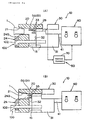
- a sequencer 50 controls the air cylinder 40 and contains a spring pin unit 51 in an insertion opening 21 of connector receiving member 20 and a control circuit 70 for controlling the supply of pressurized air to the above-mentioned air cylinder 40 by connection of spring pin unit 51.
- Figure 5 is a partial cross-sectional view of a sequencer 50 which is built in the auto-lock type continuity test unit in Figure 1.
- the spring pin unit 51 includes a body 52 recessed within the rib 28 which is formed on the connector receiving member 20.
- the body 52 is a tubular member formed of an elastic material and is provided with a flange 53 on the outer end.
- a contact 56 is slidably mounted within an aperture hole 54 in the flange 53.
- the contact 56 includes a cylindrical main body 56A, on part of which slides in the aperture 54, a flange 56B integrally formed on the outer end of the main body 56A, which is formed of a conductive material, is equipped with a stop flange 56C which is press fit onto the main body 56A on the opposite side of flange 56B with respect to the aperture 54.
- a compression coil spring 57 is installed under a compression.
- a control force (for example, 1 kgf/mm) of the compression coil spring 57 constantly biases the contact 56 in a direction towards the connector 1.
- the distance the pin 56 projects from the rib 28 is controlled by engagement of the stop flange 56C with the flange 53.
- a boss cylinder 58 formed of insulation material is press fit within tubular body 52, and on the internal surface of this boss cylinder, a sleeve 59, formed of conductive material and having a bottom 59B, is press fit to a position in which the open end 59A is somewhat contracted by boss cylinder 58.
- the sleeve 59 projects toward the opposite side such that open end 59A is oriented toward the contact 56.
- a compression coil spring 60 is incorporated, and one end thereof engages the bottom 59B of sleeve 59.
- This compression coil spring 60 is provided with a comparatively weak control force (for instance, 0.3 kgf/mm) compared with the above-mentioned compression coil spring 57.
- the other end of the compression coil spring 60 engages a base end of a contact 61.
- the contact 61 is a cylindrical member formed of a conductive material, and is provided substantially at the middle with a flange 61A fixed thereto which slides inside the sleeve 59.
- the outer tip of contact 61 is spaced from the contact 56 via a predetermined gap S.
- the tubular body 52 and the sleeve 59 are electrically connected to a control circuit 70.
- the control circuit 70 contains an electric source 71 and a driving device 72 which drives an air cylinder 40 which is constructed and arranged to drive the air cylinder 40 in a manner to be described later in detail.
- a display member (not shown), which is activated by being connected between contact 56 and contact 61 of the spring pin unit 51, allows visible detection of the existence of connector housing 1 within connector receiving member 20.
- an interlocking mechanism 100 is provided for interlocking a shift of the movable block 32 of test area 30 and a shift of the slide 24 which retains the connector housing within the connector receiving member 20.
- Interlocking mechanism 100 as shown in Figures 1, 2, 4(A) and 4(B) is formed by a link rod 101 which projects from the movable block 31 and by a cam hole 102 which is formed in the slide 24 and which is engaged by the link rod 101.
- the link rod 101 has a base end fastened to the movable block 31 and an outer end 103 which enters into the cam hole 102 and is slidably received within the connector receiving member 20.
- the outer end 103 of link rod 101 is formed in a generally hook shape and has a chamfered cam surface 103A which is formed on its lower surface that slants downwardly.
- a semicircular rib 104 which slides on the cam surface 103A of the link rod 101 is formed on the lower face of the cam hole 102 as seen in Figure 2. Since the slider 24 is biased toward the connected state by the compression coil springs 26 through the arms 24A, the semicircular rib 104 always contacts the cam face 103A of the link rod 101.
- the connector housing 1 when a worker inserts the connector housing 1 into the connector receiving member 20, the connector housing 1 can be inserted by relatively shifting the connector receiving member 20 and the test unit 30 to a separated state without interference of the probe pins 33 of the test unit 30 with the terminal fittings T of the connector housing 1 as shown in Figure 4(A).
- the connector housing 1 When the connector housing 1 is inserted, it engages with the projecting contact 56 of the spring pin unit 51, which is part of the sequencer 50 of the interlocking mechanism, and the contact 56 is depressed. Therefore, the projecting contact 56 connects with the contact 61 (shown in Figure 5) to complete control circuit 70 which operates driving the drive unit 72 and causes the rod 41 of the air cylinder 40 to extend.
- sequencer 50 causes the test unit 30 to shift to the engaged state due to the insertion of the connector housing 1 into the connector receiving member 20, and the test unit 30 engages the connector housing 1 which is retained in position by slider 24 and carries out the predetermined continuity test.
- the interlocking mechanism 100 controls the opening and closing motion of the slider 24 which is carried out in response to the relative movement of the connector receiving member 20 and the test unit 30.
- the slider 24 is positioned in a release state, and when the test unit 30 performed the continuity test, the slider 24 is positioned in the retaining condition, therefore the connector housing 1 is tightly fixed in place.
- sequencer 50 controls the air cylinder 40 by a fixed timing, for example, after completion of the continuity test, and returns the connector receiving member 20 and the test unit 30 to the relative separated condition.
- the worker can easily extract the connector housing 1 from the connector receiving member 20.
- the mechanism for providing the above-mentioned timing to the sequencer 50 can be achieved, for example, by a timer which is installed in the control circuit 70, and the test result signal of the continuity test unit 10 in which the probe pins 33 are connected (not shown in the figures) is sent to the control circuit 70 as a trigger, for example.
- a continuity test of a plurality of connector housings 1 adapted for testing a wire assembly can be carried out by engagement with a plurality of the continuity test units on a board.
- the control circuit may be configured to provide a failure treatment by returning only the continuity test unit 10 which corresponds to the defective connector housing 1 to the initial state as shown in Fig. 4(A).
- the compression coil spring 57 is an elastic body for biasing the inserted connector housing 1 toward the removal direction, wherein the connector housing 1 in a free state is ejected from the insertion opening 21 by the biasing force of the spring, as shown in Figure 4(A). Then, as the compression coil spring 57 is positioned at the connector insertion area 20 and made to be movable relative to the test area 30, the biasing force of the compression coil spring 57 can be established at a level (for example, 1 kgf/mm) sufficient to push the connector housing 1 out of the connector receiving member 20.
- a level for example, 1 kgf/mm
- the connector housing 1 when a worker inserts the connector housing 1 into the connector receiving member 20, the insertion of the connector housing 1 is carried out without interference of the probe pins 33 of the test unit with the terminal fittings T of the connector housing 1. Therefore, the connector housing 1 can be easily inserted into the connector receiving member 20, regardless of the type of the probe pins 33 utilized in the test unit.
- the present invention as 1 probe-forms and 2 probe-forms can be easily utilized, with the remarkable effect that restriction of the probe pins 33 to a particular type is reduced.
- the slider 24 opens and closes automatically. Therefore, there is an advantage that the worker can carry out the continuity testing, irrespective of the slider 24.
- the interlocking mechanism 100 of the embodiment shown in Figure 1 permits the insertion of the connector housing 1 into the connector receiving member 20 while keeping the slider 24 in the release state at the initial state, the connector housing 1 can be easily inserted into the connector receiving member 20, and as a result, there is an advantage that workability is improved.
- the biasing force can be established at a level (for example, 1 kgf/mm) sufficient to push the connector housing 1 out of the connector receiving member 20. Therefore, when the connector housing 1 is pushed out of the connector receiving member 20 by the compression coil spring 57, the compression coil spring 57 which enables the connector housing 1 to be most easily inserted is selected and, as a result, there is an advantage that workability is improved.
- FIGS. 6(A) - 6(D) are schematic cross-sectional views showing the operation of the continuity test unit 10 in a second embodiment of the present invention. Furthermore, the same reference numerals are given to the same elements as in the embodiment of Figure 1 in the discussion which follows.
- the interlocking mechanism 100 of the embodiment shown utilizes a link rod 101, a semicircular rib 104 of slider 24, and other elements as in the embodiment in Figure 1, but the initial position of link rod 101 is changed, and the slider 24 is maintained in the connected state in the initial state as shown in Figure 6(A).
- the slider 24 cooperates with the link rod 101 of test unit 30 so that the slider 24 is permitted to be pushed in.
- an interlocking air cylinder 120 which can be driven independently of the air cylinder 40, is included.
- the interlocking air cylinder 120 extends the rod 41 separately from the air cylinder 40 in the initial state shown in Figure 6(A) and in the continuity test shown in Figure 6(B).
- the air cylinder 120 contracts in synchronization with the air cylinder 40 when the air cylinder 40 extends once and then contracts, the air cylinder 120 extends the rod 41 again independently of the air cylinder 40 after the lapse of a fixed period of time as shown in Figure 6(D), and the interlocking air cylinder 120 is operated to return to the initial position.
- the above-mentioned fixed period of time T can easily be established, for example, by adapting a timer into the sequencer 50.
- FIG 7 is a diagram showing a schematic structure of a control device 50 in relation to the embodiment of Figures 6(A) - 6(D).
- a control device 50 employing a manual switch 73 is provided. Since the driving device 72 in the control device 50 allows each continuity test unit 10 to be driven simultaneously, each continuity test unit 10 operates in response to this control device 50 as follows.
- a continuity test is carried out by operating the switch 73 (refer to Figures 6(B)), and after the test, it returns to the home position (refer to Figure 6(D)) after an elapse of a predetermined prior of time T by having been contacted in harmony with the air cylinder 40 (refer to Figure 6(C)).
- an interlocking mechanism 100 fastens the connector housing 1 when testing, and then by setting the above predetermined time and shifting to a released state at a removal timing (as shown in Figure 6(C)) when both air cylinders 40 and 120 retract the rod 41, the slider 24 releases the connector housing 1 to a free condition.
- the slider 24 returns to a connected state after the connector housing 1 is pushed out by a control force of compressed coil spring 57 provided on the contact 56 of the spring pin unit 51. At least a portion of the connector housing 1 is pushed out from the insertion opening 21 before the slider 24 shifts. Therefore, as shown in Figure 6(D), the connector housing 1 can be extracted without being locked again by the slider 24.
- providing a two-step air cylinder allows the connector housing 1 to be inserted without requiring the spring pin unit 51 to contact the connector housing 1 as a result of not being given the control force of the compression coil spring 57 at insertion, thereby also making it possible to increase the control force of compression coil spring to a level as high as possible.
- Figures 8(A) and 8(B) depict a third embodiment of the invention, and show a modified example of the embodiment of Figures 6(A) - 6(D), wherein Figure 8(A) shows a schematic cross-section during insertion and Figure 8(B) shows a schematic cross-section at testing.
- the relative movement of the connector receiving member 20 and testing area 30 may be provided by any structure in which one is fastened and the other is movable or both of them are movable.
- continuity test unit 10 is not limited to a recessed type alone. Moreover, various design alternatives within the scope of the patent claims of the present invention are possible.
Landscapes
- Physics & Mathematics (AREA)
- General Physics & Mathematics (AREA)
- Testing Of Short-Circuits, Discontinuities, Leakage, Or Incorrect Line Connections (AREA)
- Manufacturing Of Electrical Connectors (AREA)
Applications Claiming Priority (2)
| Application Number | Priority Date | Filing Date | Title |
|---|---|---|---|
| JP03944897A JP3161351B2 (ja) | 1997-02-24 | 1997-02-24 | オートロック式導通検査ユニット |
| JP39448/97 | 1997-02-24 |
Publications (2)
| Publication Number | Publication Date |
|---|---|
| EP0860703A2 true EP0860703A2 (fr) | 1998-08-26 |
| EP0860703A3 EP0860703A3 (fr) | 1998-11-25 |
Family
ID=12553319
Family Applications (1)
| Application Number | Title | Priority Date | Filing Date |
|---|---|---|---|
| EP98301184A Withdrawn EP0860703A3 (fr) | 1997-02-24 | 1998-02-18 | Dispositif de contrÔle de la continuité du type à verrouillage automatique |
Country Status (4)
| Country | Link |
|---|---|
| US (2) | US6157197A (fr) |
| EP (1) | EP0860703A3 (fr) |
| JP (1) | JP3161351B2 (fr) |
| CN (1) | CN1159595C (fr) |
Cited By (4)
| Publication number | Priority date | Publication date | Assignee | Title |
|---|---|---|---|---|
| FR2798736A1 (fr) * | 1999-09-16 | 2001-03-23 | Sylea | Appareil de test electrique de boitier de connecteur |
| EP1199575A1 (fr) * | 2000-10-17 | 2002-04-24 | Sumitomo Wiring Systems, Ltd. | Dispositif de test et testeur de connecteur l'utilisant |
| CN103269006A (zh) * | 2013-05-14 | 2013-08-28 | 罗邦君 | 一种开关插座接线盒连接片自动安装装置 |
| EP3249415A1 (fr) * | 2016-05-26 | 2017-11-29 | TSK Prüfsysteme GmbH | Dispositif de carte de points de mesure pour un banc d'essai incluant la localisation de défauts |
Families Citing this family (15)
| Publication number | Priority date | Publication date | Assignee | Title |
|---|---|---|---|---|
| JP3161351B2 (ja) * | 1997-02-24 | 2001-04-25 | 住友電装株式会社 | オートロック式導通検査ユニット |
| JP3828697B2 (ja) * | 1999-12-03 | 2006-10-04 | 矢崎総業株式会社 | コネクタ導通検査具 |
| US20030125751A1 (en) * | 2001-06-27 | 2003-07-03 | Patrick Griffin | Catheter |
| JP4561461B2 (ja) * | 2005-04-28 | 2010-10-13 | 住友電装株式会社 | ワイヤーハーネスの導通検査器 |
| US7463042B2 (en) * | 2005-06-30 | 2008-12-09 | Northrop Grumman Corporation | Connector probing system |
| CN100573171C (zh) * | 2005-12-26 | 2009-12-23 | 鸿富锦精密工业(深圳)有限公司 | 连接器测试装置 |
| JP2009128216A (ja) * | 2007-11-26 | 2009-06-11 | Yazaki Corp | 導通検査治具、該導通検査治具を備えた導通検査装置、及び導通検査方法 |
| JP5566212B2 (ja) * | 2010-07-20 | 2014-08-06 | 矢崎総業株式会社 | 導通検査治具 |
| CN102147442B (zh) * | 2011-01-14 | 2014-02-26 | 富泰华工业(深圳)有限公司 | 连接器检测治具 |
| CN102944788A (zh) * | 2012-11-13 | 2013-02-27 | 南通昱品通信科技有限公司 | 光伏接线盒测试设备配套测试台 |
| CN103149495A (zh) * | 2013-02-27 | 2013-06-12 | 东莞市融汇机械设备电子有限公司 | 一种用于多路导线\连接器测试的综合测试仪 |
| CN107749538B (zh) * | 2017-11-10 | 2024-03-12 | 江苏特创科技有限公司 | 一种接口端测试组件及接口端测试装置 |
| US11128086B2 (en) * | 2018-05-11 | 2021-09-21 | The Boeing Company | Apparatus for contact insertion and retention testing |
| US12044726B2 (en) * | 2021-04-30 | 2024-07-23 | Xcerra Corporation | Calibration system |
| CN114374117B (zh) * | 2021-12-07 | 2024-04-02 | 北京天玛智控科技股份有限公司 | 电磁阀插接头、电磁阀插接装置和电磁阀测试装置 |
Family Cites Families (16)
| Publication number | Priority date | Publication date | Assignee | Title |
|---|---|---|---|---|
| FR672909A (fr) * | 1929-04-10 | 1930-01-06 | Procédé et dispositif pour la fabrication de boîtes, en particulier de boîtes àfromage | |
| US4232262A (en) * | 1978-10-12 | 1980-11-04 | Emo George C | Connector contact terminal contamination probe |
| GB2169153B (en) * | 1984-12-28 | 1988-08-03 | Sumitomo Wall Systems Ltd | Connector terminal examination device |
| DE3504606A1 (de) * | 1985-02-11 | 1986-08-14 | Helmuth 4952 Porta Westfalica Kahl | Einrichtung zum pruefen von kabeln, die mit steckern versehen sind |
| JPH025383A (ja) * | 1988-06-24 | 1990-01-10 | Yazaki Corp | コネクタ端子検出具 |
| JP2921721B2 (ja) * | 1992-04-07 | 1999-07-19 | 矢崎総業株式会社 | コネクタ端子検査具 |
| JP2908931B2 (ja) * | 1992-04-07 | 1999-06-23 | 矢崎総業株式会社 | ワイヤーハーネス検査装置 |
| JP2682594B2 (ja) * | 1992-07-27 | 1997-11-26 | 矢崎総業株式会社 | コネクタ端子検出具 |
| US5614820A (en) * | 1994-03-10 | 1997-03-25 | Sumitomo Wiring Systems, Ltd. | Connector examination device for determining a connection in a connector |
| FR2717584B1 (fr) * | 1994-03-18 | 1996-05-03 | Sm Contact | Dispositif permettant de tester un ou plusieurs câbles électriques munis de connecteurs. |
| EP0692718A1 (fr) * | 1994-07-11 | 1996-01-17 | SIX TAU S.p.A. | Procédé et appareil pour contrÔler un connecteur électrique |
| FR2726368B3 (fr) * | 1994-11-02 | 1996-12-27 | Amp France | Appareil de controle de l'assemblage de bornes |
| JP3048116B2 (ja) * | 1995-04-13 | 2000-06-05 | 矢崎総業株式会社 | コネクタ端子検査器 |
| JPH0922765A (ja) * | 1995-07-06 | 1997-01-21 | Yazaki Corp | コネクタ導通検査器及びコネクタ導通検査時の端子係止方法 |
| JPH0943299A (ja) * | 1995-08-02 | 1997-02-14 | Yazaki Corp | コネクタ検査具 |
| JP3161351B2 (ja) * | 1997-02-24 | 2001-04-25 | 住友電装株式会社 | オートロック式導通検査ユニット |
-
1997
- 1997-02-24 JP JP03944897A patent/JP3161351B2/ja not_active Expired - Fee Related
-
1998
- 1998-02-18 EP EP98301184A patent/EP0860703A3/fr not_active Withdrawn
- 1998-02-23 US US09/028,094 patent/US6157197A/en not_active Expired - Lifetime
- 1998-02-24 CN CNB981053149A patent/CN1159595C/zh not_active Expired - Fee Related
-
2000
- 2000-07-26 US US09/626,452 patent/US6480004B1/en not_active Expired - Fee Related
Cited By (5)
| Publication number | Priority date | Publication date | Assignee | Title |
|---|---|---|---|---|
| FR2798736A1 (fr) * | 1999-09-16 | 2001-03-23 | Sylea | Appareil de test electrique de boitier de connecteur |
| EP1199575A1 (fr) * | 2000-10-17 | 2002-04-24 | Sumitomo Wiring Systems, Ltd. | Dispositif de test et testeur de connecteur l'utilisant |
| US6657438B2 (en) | 2000-10-17 | 2003-12-02 | Sumitomo Wiring Systems, Ltd. | Testing unit and a connector testing apparatus using the same |
| CN103269006A (zh) * | 2013-05-14 | 2013-08-28 | 罗邦君 | 一种开关插座接线盒连接片自动安装装置 |
| EP3249415A1 (fr) * | 2016-05-26 | 2017-11-29 | TSK Prüfsysteme GmbH | Dispositif de carte de points de mesure pour un banc d'essai incluant la localisation de défauts |
Also Published As
| Publication number | Publication date |
|---|---|
| US6480004B1 (en) | 2002-11-12 |
| CN1159595C (zh) | 2004-07-28 |
| JP3161351B2 (ja) | 2001-04-25 |
| CN1191976A (zh) | 1998-09-02 |
| JPH10239377A (ja) | 1998-09-11 |
| US6157197A (en) | 2000-12-05 |
| EP0860703A3 (fr) | 1998-11-25 |
Similar Documents
| Publication | Publication Date | Title |
|---|---|---|
| US6157197A (en) | Auto-lock type continuity check unit | |
| US6316951B1 (en) | Inspection unit of a connector inspection apparatus | |
| US5203719A (en) | Lock assurance mechanism for connector | |
| US4902968A (en) | Connector terminal checking tool | |
| EP0624925B1 (fr) | Connecteur électrique avec fonction de détection d'enfichage | |
| EP0869371B1 (fr) | Unité d'essai pour tester des connecteurs | |
| US5831438A (en) | Device for testing a connector having multiple terminals therein | |
| US6102726A (en) | Connector fitting structure | |
| JPH0716390U (ja) | コネクタ検査装置 | |
| US10955487B2 (en) | High voltage diagnostic connector with service disconnect | |
| US12224527B2 (en) | Device for inspecting the assembly defect of a connector capable of fixing the position of a wire terminal | |
| KR100741339B1 (ko) | 커넥터, 커넥터 시험 장치 및 방법 | |
| US7294015B2 (en) | Connector and a method for controlling the assembly thereof | |
| EP0710847A2 (fr) | Testeur pour tester l'assemblage correct des bornes dans des connecteurs | |
| WO2006117989A1 (fr) | Testeur de conduction pour faisceau de fils | |
| US6494733B2 (en) | Connector | |
| JP3161352B2 (ja) | オートロック式導通検査ユニット | |
| JP3446675B2 (ja) | 導通検査装置 | |
| EP1199575A1 (fr) | Dispositif de test et testeur de connecteur l'utilisant | |
| JP3608330B2 (ja) | オートロック式導通検査ユニットおよびそれを用いた導通検査装置 | |
| JPH08320355A (ja) | コネクタ検査装置 | |
| JP3446676B2 (ja) | 導通検査装置 | |
| JPH0982444A (ja) | コネクタ検査器 | |
| JP3211760B2 (ja) | リテーナ本係止機構 | |
| CZ298651B6 (cs) | Zarízení k otresuvzdornému zablokování zástrcky vjejí zastrcené poloze |
Legal Events
| Date | Code | Title | Description |
|---|---|---|---|
| PUAI | Public reference made under article 153(3) epc to a published international application that has entered the european phase |
Free format text: ORIGINAL CODE: 0009012 |
|
| 17P | Request for examination filed |
Effective date: 19980305 |
|
| AK | Designated contracting states |
Kind code of ref document: A2 Designated state(s): DE FR GB IT |
|
| AX | Request for extension of the european patent |
Free format text: AL;LT;LV;MK;RO;SI |
|
| PUAL | Search report despatched |
Free format text: ORIGINAL CODE: 0009013 |
|
| AK | Designated contracting states |
Kind code of ref document: A3 Designated state(s): AT BE CH DE DK ES FI FR GB GR IE IT LI LU MC NL PT SE |
|
| AX | Request for extension of the european patent |
Free format text: AL;LT;LV;MK;RO;SI |
|
| AKX | Designation fees paid |
Free format text: DE FR GB IT |
|
| 17Q | First examination report despatched |
Effective date: 20080225 |
|
| STAA | Information on the status of an ep patent application or granted ep patent |
Free format text: STATUS: THE APPLICATION IS DEEMED TO BE WITHDRAWN |
|
| 18D | Application deemed to be withdrawn |
Effective date: 20080708 |