EP0860760B1 - Gerät zum Bearbeiten eines Werkstückes sowie damit zu benutzende Verfahren - Google Patents
Gerät zum Bearbeiten eines Werkstückes sowie damit zu benutzende Verfahren Download PDFInfo
- Publication number
- EP0860760B1 EP0860760B1 EP98200428A EP98200428A EP0860760B1 EP 0860760 B1 EP0860760 B1 EP 0860760B1 EP 98200428 A EP98200428 A EP 98200428A EP 98200428 A EP98200428 A EP 98200428A EP 0860760 B1 EP0860760 B1 EP 0860760B1
- Authority
- EP
- European Patent Office
- Prior art keywords
- tool
- control unit
- workpiece
- axis
- rotation
- Prior art date
- Legal status (The legal status is an assumption and is not a legal conclusion. Google has not performed a legal analysis and makes no representation as to the accuracy of the status listed.)
- Expired - Lifetime
Links
Images


Classifications
-
- G—PHYSICS
- G05—CONTROLLING; REGULATING
- G05B—CONTROL OR REGULATING SYSTEMS IN GENERAL; FUNCTIONAL ELEMENTS OF SUCH SYSTEMS; MONITORING OR TESTING ARRANGEMENTS FOR SUCH SYSTEMS OR ELEMENTS
- G05B19/00—Program-control systems
- G05B19/02—Program-control systems electric
- G05B19/18—Numerical control [NC], i.e. automatically operating machines, in particular machine tools, e.g. in a manufacturing environment, so as to execute positioning, movement or co-ordinated operations by means of program data in numerical form
- G05B19/408—Numerical control [NC], i.e. automatically operating machines, in particular machine tools, e.g. in a manufacturing environment, so as to execute positioning, movement or co-ordinated operations by means of program data in numerical form characterised by data handling or data format, e.g. reading, buffering or conversion of data
- G05B19/4083—Adapting program, configuration
Definitions
- the invention relates to an apparatus for working a workpiece, which apparatus comprises drive means for rotating a carrier about an axis of rotation, a tool for working said workpiece, means for moving said tool in an x-direction and a y-direction with respect to said drive means, and a control unit comprising a memory for one or more control programmes, wherein said control unit is arranged for controlling said moving means in accordance with a control programme, in such a manner that said tool follows one or more desired paths for working the workpiece, and also to a method for storing a control programme for such an apparatus and to a method for controlling such an apparatus.
- Apparatus of the above kind are known in various embodiments thereof, and they may be adapted for working the workpiece, whether or not by removing stock.
- Known apparatus are for example lathes, forming lathes or the like.
- a control programme is stored in the memory in a teaching or programming phase in the known apparatus, after which the control unit controls the moving means in accordance with the control programme in the production phase, so that the tool is moved in the desired path or paths along the workpiece, which is clamped in the apparatus, so as to carry out the desired working step on the workpiece.
- the object of the invention is to provide an apparatus of the kind referred to in the introduction, wherein the above drawbacks have been overcome in a simple and efficient manner.
- the invention is based on the insight that by storing the apparatus parameters, such as the angle between the axis of rotation and one of the directions of movement, and preferably also the tool contour and the position of said contour with respect to the axis of rotation, in the control programme, said control programme is in fact made independent of said parameters.
- the control unit can establish the difference between the values stored at the control programme in question and the measured values, and, if a difference is detected, adapt the control programme so that the tool will follow the desired path or paths in spite of any such deviation. This means that a new teaching or programming phase for continuing the production in accordance with an already stored control programme is no longer necessary when the tool is exchanged or worked.
- a control programme which has been stored in a particular apparatus in a teaching or programming phase together with the associated apparatus parameter(s), can be used in other apparatus without any problem, whereby said control programme can be adapted to the apparatus in question in a simple manner by having the control unit measure the apparatus parameter(s). All apparatus will then have the same production time.
- a teaching or programming phase is only required for one apparatus, after which the control programme can be used for all other apparatus which are used for producing the same product.
- Another advantage of the apparatus according to the invention is furthermore the fact that a user of the apparatus can order a control programme for the manufacture of a particular product from the manufacturer or from another supplier, which programme can be stored in a teaching or programming phase on an available machine by the supplier, and subsequently be made available to the user.
- the invention also provides a method for storing a control programme for an apparatus for working a workpiece, which apparatus comprises drive means for rotating a carrier about an axis of rotation, a tool for working the workpiece, means for moving said tool with respect to said drive means in an x-direction and a y-direction, and a control unit comprising a memory for one or more control programmes, wherein a working step is carried out on the workpiece in a teaching or programming phase, and one or more paths followed by the tool during the working of the workpiece are stored in the memory in the form of a control programme for said moving means, characterized by the characterising portion of claim 13.
- the invention furthermore provides a method for controlling an apparatus for working a workpiece, which apparatus comprises drive means for rotating a carrier about an axis of rotation, a tool for working the workpiece, means for moving said tool with respect to said drive means in an x-direction and a y-direction, and a control unit comprising a memory for storing one or more control programmes and at least one apparatus parameter, wherein said control unit is arranged for controlling said moving means in accordance with a control programme, in such a manner that said tool follows one or more desired paths for working the workpiece, characterized by the characterising portion of claim 15.
- US 5,387,061 discloses a compensation system for a computer-controlled machining apparatus which alters the pre-programmed path of a cutting tool if the actual contour of a workpiece differs from an expected contour.
- Fig. 1 is a plan view of a first embodiment of the apparatus according to the invention.
- Fig. 2 is a very diagrammatic, larger-scale front view of a part of the apparatus of Fig. 1.
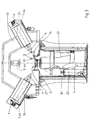
- Fig. 3 is a diagrammatic cross-sectional view of a second embodiment of the apparatus according to the invention, which shows the measuring unit is a first position thereof.
- Fig. 4 shows part of the cross-sectional view of Fig. 3 on a larger scale.
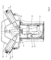
- Fig. 5 is a cross-sectional view which corresponds with Fig. 3, which shows the second measuring unit in a second position thereof.
- Fig. 6 shows part of the cross-sectional view of Fig. 5 on a larger scale.
- Fig. 7 is a plan view of the part of the apparatus shown in Figs. 4 and 6, wherein the measuring unit and the tools are shown in different positions thereof.
- Fig. 8 is a simplified block diagram of the control unit of the apparatus of Figs. 1 and 3.
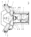
- Fig. 9 is a cross-sectional view corresponding with Fig. 3 of the apparatus according to the invention, wherein a forming tool is mounted on the carrier of the drive means, and wherein an alternative measuring unit is mounted on said forming tool.
- Fig. 1 is a plan view of a forming machine which comprises a machine bed 1, a drive unit 2 for rotating a workpiece (not shown) about an axis of rotation 3, a forming roller 4 for working the workpiece, and means 5, 6 for moving forming roller 4 in an x-direction and a y-direction with respect to drive unit 2.
- Said moving means 5, 6 comprises a bedslide 5, which is capable of movement in x-direction, and a top slide 6, which is capable of movement in y-direction on said bedslide 5 and which supports forming roller 4.
- the x and y-directions or axes extend perpendicularly to each other in this embodiment, but this is not necessary.
- the forming machine that has been discussed so far is known per se, it is described in the applicant's EP-A-0 125 720, and the construction and operation of this machine will not be discussed in detail herein. For a more detailed explanation reference is made to EP-A-0 125 720.
- Drive unit 2 is provided with a rotary carrier 9, on which a forming tool is mounted during normal operation, on which the workpiece, which for example consists of a metal sheet, which may or may not be preformed, is transformed.
- a forming tool which for example consists of a metal sheet, which may or may not be preformed, is transformed.
- Fig. 9 shows an embodiment of the apparatus with a forming tool being mounted on carrier 9. This embodiment will be discussed in more detail hereafter.
- control unit 7 will then control moving means 5, 6, in such a manner that the workpiece is transformed as a result of forming roller 4 following one or more paths on the forming tool.
- the control programme required for this operation is stored in memory 8 in a teaching or programming phase.
- said control programme comprises the x and y-positions of forming roller 4, on the basis of which moving means 5, 6 are controlled by control unit 7. It will be apparent that by controlling the moving means 5, 6 along the indicated x and y-axes, forming roller 4 can be moved along any desired path along axis of rotation 3.
- a similar drawback occurs with the known forming machine when forming roller 4 is to be exchanged or worked, since the contour and/or the position of said contour with respect to axis of rotation 3 will no longer correspond with the contour and/or the position stored during the teaching or programming phase.
- the aforesaid angle and contour and/or position are in fact apparatus parameters which influence the control programme.
- control unit 7 With the forming machine according to the invention the existing control programme may be maintained, in spite of the fact that the apparatus parameter(s) has (have) changed, since control unit 7 is arranged for measuring one or more of these parameters.
- the parameter(s) is (are) stored at the control programme in memory 8 during the teaching or programming phase. In the event of parameters being changed by maintenance work or by another cause, said parameters will be measured anew and be compared with the parameters that are stored in the memory. If there appears to be a difference between a recorded parameter and the measured value, control unit 7 will adapt the control programme in question, in such a manner that forming roller 4 will follow the desired paths all the same.
- the forming machine comprises a measuring unit 11, by means of which the control unit 7 can measure the angle between axis of rotation 3 and the y-direction.
- measuring unit 11 includes two measuring elements 12, which each comprise a laser diode 13 and a receiver 14.
- Measuring unit 11 comprises a mounting unit 15, which is fixed to carrier 9 and which has two U-shaped supporting arms 16, 17, which each support a diode-receiver pair 13, 14.
- Mounting unit 15 furthermore comprises an adjusting arm 18, which is supported on machine bed 1 with an adjusting element 19, whereby adjusting element 19 is adjusted such that the light beam of diode 13 extends exactly perpendicularly to the plane in which axis of rotation 3 and the y-axis lie.
- control unit 7 will control moving means 5, 6 in such a manner that the circumference of the forming roller 4 which is used in this example will be scanned carefully by measuring element 12 of the first U-shaped arm 16, whereby the control unit will store the x and y-positions of moving means 5, 6 that are associated with one or more predetermined points on said circumference, preferably the highest point or several points of forming roller 4. Then the control unit will move forming roller 4 to measuring element 12 of second U-shaped arm 17, which position is schematically illustrated in Fig. 1.
- Control unit 7 will then control moving means 5, 6 again, so that the measuring element in question of arm 17 will scan the circumference of forming roller 4 and store the x and y-positions of the same point or points. Since the control unit 7 will establish the movement of moving means 5, 6 in a usual manner, by means of measuring elements 20, 21, the control unit can simply calculate the angle between the x or y-direction and axis of rotation 3 from the two different x and y-positions of the predetermined point of forming roller 4. This angle will be stored in memory 8 at the control programme which is stored in said memory 8 in the teaching or programming phase.
- control unit 7 When the forming machine is subsequently prepared for a production phase with the forming tool in question, control unit 7 will first measure the angle between axis of rotation 3 and the x or y-direction in the above-described manner, and compare said angle with the angle stored at the control programme in question. If a difference is detected between the stored angle and the measured angle, control unit 7 can adapt the x and y-positions of moving means 5, 6 to the changed angle in a simple manner, so that the stored control programme can be used in spite of a change in said angle.
- This adaptation may for example take place by converting the x and y-positions angle into orthogonal positions with respect to axis of rotation 3 on the basis of the angle that has been measured in the teaching or programming phase. Then said orthogonal positions are converted back into corrected x and y-positions for moving means 5, 6 again on the basis of the changed angle, wherein the changed angle is stored for any future corrections in case changes in the angle should occur again.
- the above-described apparatus and method also have the advantage that the control programme which has been stored in a teaching or programming phase on a first forming machine can be simply used with another forming machine having comparable settings in a particular production phase, because a control unit of this other forming machine will first measure the angle between the axis of rotation and the x or y-direction again, and if a difference is detected between the measured angle and the stored angle, the control unit can adapt the control programme to the associated forming machine.
- This is a significant advantage, since only one control programme needs to be stored in a teaching or programming phase in the case of mass production with several forming machines, after which this control programme can be used on all forming machines.
- Another advantage that is achieved thereby is the fact that the production time will be exactly the same for all forming machines.
- Fig. 3 shows a second embodiment of the apparatus according to the invention, which is described in more detail in the applicant's patent application of the same date, to which reference may be had for a more detailed description.
- a drive unit 22 can be moved in the direction of axis of rotation 3, which extends in horizontal direction in this case, by means of a hydraulic cylinder 23, whereby the movement is measured by a measuring element 24.
- the movement of drive unit 22 in the direction of axis of rotation 3 corresponds with the movement of the bedslide in the y-direction in the forming machine of Fig. 1.
- two forming rollers 4 are disposed on either side of axis of rotation 3, whereby the forming rollers are only capable of movement in y-direction by means of an associated moving means 6.
- the movement of forming rollers 4 in the x-direction is measured by measuring elements 25, 26.
- the operation of the forming machine shown in Fig. 3 corresponds with the operation of the forming machine of Fig. 1.
- a measuring unit 11 comprising two measuring elements 12 is used again, which measuring elements are disposed on U-shaped arms 16 and 17.
- the measuring unit 11 of the forming machine shown in Fig. 3 possesses another mounting unit 27, which can be mounted on rotary carrier 9 of drive unit 22.
- Fig. 3 shows drive unit 22 in a first position thereof, in which position the circumference of forming roller 4 can be scanned by means of measuring element 12 of U-shaped arm 16, all this under the control of control unit 7, which controls moving means 6, 23.
- Said scanning makes it possible to determine the x and y-positions of one or more points on the circumference of forming roller 4, preferably at least the highest point.
- drive unit 22 is moved downwards to the position shown in Fig. 5.
- the circumference of forming roller 4 can be scanned with the measuring element 12 of U-shaped arm 17.
- control unit 7 can determine the angle between the y-direction and axis of rotation 3, which coincides with the x-direction in this embodiment, and store it in the above-described manner at the control programme and/or compare it with the stored angle.
- the control programme can be adapted again, as a result of which the above-described advantages will be obtained.
- mounting unit 27 comprises two diametrically opposite adjusting arms 28, 29, which are capable of cooperation with a stop member 31, which is mounted on a frame part 30.
- Fig. 7 is a schematic plan view of the part shown in Figs. 4 and 6, wherein the forming roller present on either side of axis of rotation 3 is shown in two different positions thereof, and wherein also measuring elements 12 are shown in two different positions thereof. From this plan view it appears that the adjusting arms 28, 29 cooperate with the stop member 31 in such a manner that the light beam of diode 13 extends perpendicularly to the common plane of the axis of rotation and the x-direction. This helps to prevent measuring errors.
- a carrier beam 32 which is fixed to the frame of the forming machine in a manner which is not shown.
- Said carrier beam 32 also carries a clamping unit 10 (not shown), by means of which a workpiece to be worked can be clamped against a forming tool to be mounted on carrier 9.
- Fig. 9 shows an embodiment of the forming machine according to Figs. 3 and 5, wherein a forming tool 33 is mounted on carrier 9 of drive unit 22.
- a measuring unit 34 which comprises a measuring element 12, which, as described above, consists of a laser diode and a receiver, which are carried by a U-shaped arm 16.
- Two adjusting arms 28 are disposed in diametrically opposite relationship in the same manner as with measuring unit 11, which adjusting arms are capable of cooperation with the stop member 31 mounted on frame part 30. This makes it possible to lock measuring unit 34 in a measuring position for measuring the contour and the position of forming rollers 4 shown on the right and on the left in the sectional view according to Fig. 9.
- Control unit 7 can move forming roller 4 and drive unit 22 with respect to each other by controlling hydraulic cylinder and the respective moving means 6, in such a manner that measuring element 12 of measuring unit 34 will scan the contour of forming roller 4, which contour is stored in memory 8 in the form of x and y-positions.
- the x and y-position(s) that have been stored by means of measuring unit 34 may be considered as zero point(s) for the teaching or programming phase.
- measuring unit 34 is first mounted on forming tool 33 again before the control programme is executed in the production phase, after which the contour of forming roller 4 is scanned again.
- the x and y-position obtained thereby which may be considered as zero point(s) for the reproduction phase, are compared by control unit 7 with the x and y-positions which are stored in memory 8, and if differences are detected, control unit 7 will adapt the control programme, so that the correct path/paths will be travelled by the forming roller in spite of changes in the contour and/or the position of forming roller 4 or in the position of the front surface of forming tool 33.
- This adaptation can be achieved in a simple manner in this case, for example by correcting the x and y-positions of moving means 5, 6 for each point of the path/paths stored in the memory in dependence on the differences that have been measured.
- the forming machine according to Figs. 3 and 9 may also comprise more than two forming rollers, whereby the measuring unit may have one adjusting arm for each forming roller.
- the measuring unit may have one adjusting arm for each forming roller.
- the invention has been explained by means of a forming machine in the above, the invention may also be used with other types of apparatus for working a workpiece, for example with a lathe. It is noted that it is also possible to use other types of measuring elements than the above-described measuring elements 12 comprising a laser diode and a receiver, for example mechanical, electronic, electromagnetic, photographic or optical measuring means, or measuring means that operate acoustically or pneumatically.
Landscapes
- Engineering & Computer Science (AREA)
- Human Computer Interaction (AREA)
- Manufacturing & Machinery (AREA)
- Physics & Mathematics (AREA)
- General Physics & Mathematics (AREA)
- Automation & Control Theory (AREA)
- Numerical Control (AREA)
- Turning (AREA)
- Electrical Discharge Machining, Electrochemical Machining, And Combined Machining (AREA)
- Grinding And Polishing Of Tertiary Curved Surfaces And Surfaces With Complex Shapes (AREA)
- Machine Tool Copy Controls (AREA)
- Manipulator (AREA)
Claims (16)
- Vorrichtung zum Bearbeiten eines Werkstücks, welche Vorrichtung Antriebsmittel (2, 22) zum Drehen eines Trägers (9) um eine Drehachse (3) herum aufweist, ein Werkzeug (4) zum Bearbeiten des Werkstücks, Mittel (5, 6, 23) zum Bewegen des Werkstücks (4) in eine X-Richtung und eine Y-Richtung bezüglich der Antriebsmittel (2, 22), sowie eine Steuereinheit (7) mit einem Speicher (8) für zumindest ein Steuerungsprogramm, wobei die Steuerungseinheit (7) so ausgestaltet ist, dass sie die Bewegungsmittel (5, 6, 23) gemäß einem Steuerungsprogramm bewegt, so dass das Werkzeug (4) zumindest einem gewünschten Pfad zum Bearbeiten des Werkstücks folgt, dadurch gekennzeichnet, dass die Steuerungseinheit (7) zum Messen von zumindest dem Winkel zwischen der Drehachse (3) und einem Bewegungsmittel (5, 6) der Vorrichtung als Vorrichtungsparameter ausgestaltet ist, welcher Vorrichtungsparameter in dem zumindest einem Steuerungsprogramm gespeichert wird, wobei die Steuerungseinheit (7) zum Vergleichen des gespeicherten Vorrichtungsparameters mit dem gemessenen Vorrichtungsparameter ausgestaltet ist und wobei die Steuerungseinheit (7), wenn ein Unterschied zwischen dem gespeicherten Vorrichtungsparameter und dem gemessenen festgestellt wird, das zumindest eine Steuerungsprogramm so anpasst, dass das Werkzeug (4) dem zumindest einen gewünschten Pfad folgt.
- Vorrichtung nach Anspruch 1, wobei die Vorrichtung eine Messeinheit (11) zum Messen von zumindest einem bestimmten Punkt am Umfang des Werkzeugs (4) an einer ersten und einer zweiten Position bezüglich der Drehachse aufweist, wobei die Steuerungseinheit (7) das Bewegungsmittel (5, 6, 23) zum Bewegen des Werkzeugs (4) mit dem bestimmten Punkt in die erste und zweite Position aufweist, wobei die Steuerungseinheit (7) die Entfernung bestimmt, welche das Werkzeug (4) in X- und Y-Richtung zurücklegt, und wobei die Steuerungseinheit (7) den Winkel zwischen der Drehachse und einem der Bewegungsmittel (5, 6, 23) auf der Basis dieser Entfernung bestimmt.
- Vorrichtung nach Anspruch 1 oder 2, wobei die Messeinheit (11) ein erstes und ein zweites Messelement (12) zum Messen von zumindest dem bestimmten Punkt in der ersten und zweiten Position aufweist.
- Vorrichtung nach Anspruch 1, 2 oder 3, wobei die Messeinheit (11) mit dem Träger des Antriebsmittels (2) gekoppelt werden kann.
- Vorrichtung nach einem der vorangehenden Ansprüche, wobei die Steuerungseinheit (7) zum Messen des Werkzeugumfangs und der Position dieses Umfangs bezüglich der Drehachse (3) als Vorrichtungsparameter ausgestaltet ist.
- Vorrichtung nach Anspruch 5, wobei die Messeinheit (11) mit dem Antriebsmittelträger gekoppelt werden kann, wobei die Steuerungseinheit (7) die Bewegungsmittel (5, 6, 23) steuert, so dass ein Messelement (12) der Messeinheit (11) die Werkzeugkontur abtastet, und wobei die Steuerungseinheit (7) die zugehörigen X- und Y-Positionen bestimmt und sie mit den X- und Y-Positionen vergleicht, welche in dem Speicher (8) gespeichert sind.
- Vorrichtung nach einem der Ansprüche 2 bis 6, wobei die Messeinheit (11) Anpassmittel (18, 19, 20, 29) zum Anpassen einer Messposition der Messeinheit (11) bezüglich einer gemeinsamen Ebene der Drehachse (3) und einer der Bewegungsrichtungen aufweist.
- Vorrichtung nach Anspruch 7, wobei das Anpassmittel (18, 19) einen Anpassarm (18) aufweist, welcher mit einem Maschinenbett zusammenarbeitet.
- Vorrichtung nach einem der Ansprüche 2 bis 7, wobei zumindest zwei Werkzeuge (4) zum Bearbeiten des Werkstücks und Bewegungsmittel (5, 6, 23) für jedes Werkzeug (4) vorgesehen sind, wobei das Anpassmittel (18, 19) einen Anpassarm (18) für jedes Werkzeug (4) aufweist, welcher mit einem Anschlag (31) zusammenarbeitet, welcher an einem Rahmenteil (30) der Vorrichtung angebracht ist, oder wobei ein Anschlag (31) an dem Rahmenteil (30) für jedes Werkzeug (4) angebracht ist, welcher Anschlag (31) mit einem Anpassarm (18) der Anpassmittel (18, 19) zusammenarbeiten kann.
- Vorrichtung nach einem der Ansprüche 7 bis 9, wobei jedes Messelement (12) eine Laserdiode und einen Empfänger aufweist, wobei der Lichtstrahl der Laserdiode sich senkrecht zu der gemeinsamen Ebene in der Messposition erstreckt.
- Vorrichtung nach einem der vorangehenden Ansprüche, wobei die Vorrichtung eine Werkzeugmaschine ist.
- Vorrichtung nach Anspruch 11, wobei ein formendes Werkzeug (4) an dem Antriebsmittelträger befestigt ist und wobei die Messeinheit (11) an dem formenden Werkzeug (4) angebracht sein kann.
- Verfahren zum Vorbereiten eines Steuerungsprogramms für eine Vorrichtung zum Bearbeiten eines Werkstücks, welche Vorrichtung Antriebsmittel (2, 22) zum Drehen eines Trägers (9) um eine Drehachse (3) herum aufweist, ein Werkzeug (4) zum Bearbeiten des Werkstücks, Mittel zum Bewegen (5, 6, 23) des Werkstücks (4) bezüglich der Antriebsmittel (2, 22) in X- und Y-Richtung, und eine Steuerungseinheit (7) mit einem Speicher (8) für zumindest ein Steuerungsprogramm, wobei ein Arbeitsschritt an dem Werkstück in einer Teach-in- oder Programmierphase ausgeführt wird, und wobei zumindest ein Pfad, welchem das Werkzeug (4) während der Bearbeitung des Werkstücks folgt, in dem Speicher (8) in Form eines Steuerungsprogramms für die Bewegungsmittel (5, 6, 23) gespeichert wird, dadurch gekennzeichnet, dass zumindest der Winkel zwischen der Drehachse (3) und einer der Bewegungsrichtungen des Werkzeugs gemessen und in dem Speicher (8) gespeichert wird.
- Verfahren nach Anspruch 13, wobei die Werkzeugkontur und die Position der Kontur bezüglich der Drehachse (3) gemessen und in dem Speicher (8) gespeichert werden.
- Verfahren zum Steuern einer Vorrichtung zum Bearbeiten eines Werkstücks, welche Vorrichtung Antriebsmittel zum Drehen eines Trägers um eine Drehachse herum aufweist, ein Werkzeug zum Bearbeiten des Werkstücks, Mittel zum Bewegen des Werkzeugs bezüglich der Antriebsmittel in X- und Y-Richtung sowie eine Steuerungseinheit mit einem Speicher zum Speichern von zumindest einem Steuerungsprogramm und zumindest einem Vorrichtungsparameter, wobei die Steuerungseinheit zum Steuern der Bewegungsmittel gemäß einem Steuerungsprogramm ausgestaltet ist, und zwar so, dass das Werkzeug zumindest einem gewünschten Pfad zum Bearbeiten des Werkstücks folgt, dadurch gekennzeichnet, dass zumindest ein Vorrichtungsparameter gemessen und mit dem gespeicherten Vorrichtungsparameter verglichen wird, und, wenn ein Unterschied erfasst wird zwischen dem gespeicherten Vorrichtungsparameter und dem gemessenen, das zumindest eine Steuerungsprogramm so angepasst wird, dass das Werkzeug dem gewünschten Pfad folgt, wobei der Winkel zwischen der Drehachse und einer der Bewegungsrichtungen des Werkzeugs als der Vorrichtungsparameter verwendet werden.
- Verfahren nach Anspruch 15, wobei die Werkzeugkontur und die Position der Kontur bezüglich der Drehachse (3) als Vorrichtungsparameter verwendet werden.
Applications Claiming Priority (2)
| Application Number | Priority Date | Filing Date | Title |
|---|---|---|---|
| NL1005318A NL1005318C2 (nl) | 1997-02-20 | 1997-02-20 | Inrichting voor het bewerken van een werkstuk, alsmede werkwijzen voor toepassing bij een dergelijke inrichting. |
| NL1005318 | 1997-02-20 |
Publications (2)
| Publication Number | Publication Date |
|---|---|
| EP0860760A1 EP0860760A1 (de) | 1998-08-26 |
| EP0860760B1 true EP0860760B1 (de) | 2001-11-21 |
Family
ID=19764453
Family Applications (1)
| Application Number | Title | Priority Date | Filing Date |
|---|---|---|---|
| EP98200428A Expired - Lifetime EP0860760B1 (de) | 1997-02-20 | 1998-02-12 | Gerät zum Bearbeiten eines Werkstückes sowie damit zu benutzende Verfahren |
Country Status (9)
| Country | Link |
|---|---|
| US (1) | US6195595B1 (de) |
| EP (1) | EP0860760B1 (de) |
| AT (1) | ATE209371T1 (de) |
| CA (1) | CA2229897C (de) |
| DE (1) | DE69802576T2 (de) |
| DK (1) | DK0860760T3 (de) |
| ES (1) | ES2168720T3 (de) |
| NL (1) | NL1005318C2 (de) |
| PT (1) | PT860760E (de) |
Families Citing this family (7)
| Publication number | Priority date | Publication date | Assignee | Title |
|---|---|---|---|---|
| US6625866B2 (en) * | 1996-03-22 | 2003-09-30 | The Boeing Company | Determinant passively-located pogo machine |
| US7900352B2 (en) * | 2001-05-18 | 2011-03-08 | Hess Engineering, Inc. | Method and apparatus for manufacturing a catalytic converter |
| CN1274948C (zh) * | 2001-05-18 | 2006-09-13 | 赫斯工程股份有限公司 | 用于制造催化式排气净化器的方法和装置 |
| US6983632B2 (en) * | 2002-11-20 | 2006-01-10 | Hess Engineering, Inc. | Method and apparatus for spinning to a constant length |
| CN100434660C (zh) | 2003-05-13 | 2008-11-19 | 赫斯工程股份有限公司 | 制造催化式排气净化器的方法和装置 |
| JP2009502505A (ja) * | 2005-07-19 | 2009-01-29 | ハンセン,トーマス,シー. | 接線方向製造装置 |
| CN105825050B (zh) * | 2016-03-11 | 2018-04-06 | 四川川大智胜软件股份有限公司 | 一种实现自行高炮多轴线一致性检查的方法 |
Family Cites Families (19)
| Publication number | Priority date | Publication date | Assignee | Title |
|---|---|---|---|---|
| US3605909A (en) * | 1963-01-11 | 1971-09-20 | Jerome H Lemelson | Tooling machine having surface sensing program starting |
| DE2509586C3 (de) * | 1975-03-05 | 1980-03-27 | Gebrueder Boehringer Gmbh, 7320 Goeppingen | Einrichtung zum Einstellen einer Werkzeugschneide an einer spanabhebenden Werkzeugmaschine |
| NL8301678A (nl) * | 1983-05-11 | 1984-12-03 | Johan Massee | Forceermachine. |
| JPS60126709A (ja) * | 1983-12-14 | 1985-07-06 | Fanuc Ltd | 位置制御方法 |
| JPS61109109A (ja) * | 1984-10-31 | 1986-05-27 | Sankyo Seiki Mfg Co Ltd | 平面多関節型ロボツトの位置決め方法 |
| JPS61195407A (ja) * | 1985-02-25 | 1986-08-29 | Hitachi Zosen Corp | 数値制御デ−タ処理方法 |
| US4807145A (en) * | 1986-10-15 | 1989-02-21 | Topre Corporation | Method and apparatus for measuring the shape, size, etc., of a rotary tool |
| JP2673810B2 (ja) | 1988-02-25 | 1997-11-05 | 日本スピンドル製造株式会社 | スピニングマシンによる絞り加工方法 |
| IL89484A (en) * | 1989-03-03 | 1992-08-18 | Nct Ltd Numerical Control Tech | System for automatic finishing of machined parts |
| KR920003740B1 (ko) | 1989-10-24 | 1992-05-09 | 한국과학기술연구원 | 3차원 직교좌표형 고속정밀측정기 |
| JPH03251378A (ja) * | 1990-02-28 | 1991-11-08 | Fanuc Ltd | ロボットのキャリブレーション方式 |
| US5387061A (en) * | 1990-12-14 | 1995-02-07 | The United States Of America As Represented By The United States Department Of Energy | Parameter monitoring compensation system and method |
| US5255199A (en) * | 1990-12-14 | 1993-10-19 | Martin Marietta Energy Systems, Inc. | Cutting tool form compensaton system and method |
| US5419222A (en) * | 1992-10-08 | 1995-05-30 | The United States Of America As Represented By The United States Department Of Energy | Method for measuring the contour of a machined part |
| US5537850A (en) * | 1992-12-18 | 1996-07-23 | Rays Engineering Co., Ltd. | Method of shaping a wheel |
| US5363185A (en) | 1992-12-23 | 1994-11-08 | The United States Of America As Represented By The Secretary Of The Air Force | Method and apparatus for identifying three-dimensional coordinates and orientation to a robot |
| US5457367A (en) * | 1993-08-06 | 1995-10-10 | Cycle Time Corporation | Tool center point calibration apparatus and method |
| NL1003403C2 (nl) * | 1996-06-24 | 1998-01-07 | Johan Massee | Inrichting voor het bewerken van een werkstuk. |
| NL1005319C2 (nl) * | 1997-02-20 | 1998-08-24 | Johan Massee | Inrichting voor het bewerken van een werkstuk. |
-
1997
- 1997-02-20 NL NL1005318A patent/NL1005318C2/nl not_active IP Right Cessation
-
1998
- 1998-02-12 ES ES98200428T patent/ES2168720T3/es not_active Expired - Lifetime
- 1998-02-12 DK DK98200428T patent/DK0860760T3/da active
- 1998-02-12 PT PT98200428T patent/PT860760E/pt unknown
- 1998-02-12 AT AT98200428T patent/ATE209371T1/de active
- 1998-02-12 DE DE69802576T patent/DE69802576T2/de not_active Expired - Lifetime
- 1998-02-12 EP EP98200428A patent/EP0860760B1/de not_active Expired - Lifetime
- 1998-02-18 CA CA002229897A patent/CA2229897C/en not_active Expired - Fee Related
- 1998-02-18 US US09/025,497 patent/US6195595B1/en not_active Expired - Lifetime
Also Published As
| Publication number | Publication date |
|---|---|
| DE69802576T2 (de) | 2002-08-01 |
| DK0860760T3 (da) | 2002-03-11 |
| ATE209371T1 (de) | 2001-12-15 |
| ES2168720T3 (es) | 2002-06-16 |
| CA2229897C (en) | 2006-07-25 |
| DE69802576D1 (de) | 2002-01-03 |
| NL1005318C2 (nl) | 1998-08-24 |
| CA2229897A1 (en) | 1998-08-20 |
| US6195595B1 (en) | 2001-02-27 |
| EP0860760A1 (de) | 1998-08-26 |
| PT860760E (pt) | 2002-05-31 |
Similar Documents
| Publication | Publication Date | Title |
|---|---|---|
| EP0816958B1 (de) | Gerät zum Bearbeiten eines Werkstückes | |
| US6593541B1 (en) | Method for machining workpieces and machine tool | |
| US5095788A (en) | Method for compensating thermally induced displacement in machine tools | |
| US5513113A (en) | Method of and device for correcting position of cutting-edge of tool in numerically controlled machine tool | |
| US5088181A (en) | Sheet metal part machining system | |
| US5399049A (en) | V-shaped groove forming machine and its control method | |
| CA2045600A1 (en) | Dynamic correction of servo following errors in a computer-numerically-controlled system and fixed cycle utilizing same | |
| US5689988A (en) | CNC-controlled pipe bending machine | |
| EP0341968B1 (de) | Numerisch gesteuerte Werkzeugmaschine | |
| GB2056897A (en) | Machine tool with laser cutting device | |
| EP0860760B1 (de) | Gerät zum Bearbeiten eines Werkstückes sowie damit zu benutzende Verfahren | |
| JP7268158B2 (ja) | レーザビームによりパイプまたは成形材を切断するパイプ加工機械 | |
| CN114918526A (zh) | 一种基于线激光扫描的数控机床焊接轨迹修正系统及方法 | |
| US6745101B2 (en) | Deflection compensation for numerical controlled manufacturing | |
| JPH10133728A (ja) | 製品検査データの自動フィードバック装置及びこの装置を用いた自動プログラム修正方法 | |
| JP2000504867A (ja) | ワークピースおよびツールキャリッジの運動用の改良されたモニタシステム | |
| US6470776B1 (en) | Clamping device and method of operation for a CNC machine | |
| US5435360A (en) | Method for positioning a machine element having a reference point relative to a reference point provided at an abutment | |
| JP2020015130A (ja) | ワーク移動位置決め装置 | |
| CZ87798A3 (cs) | Způsob přesného určení nulového bodu jehly šicího stroje šicího automatu a zařízení k provádění tohoto způsobu | |
| JP3730313B2 (ja) | 折曲げ加工機による加工方法及びその方法を用いた折曲げ加工機 | |
| EP0618520A1 (de) | Verzahnungsmaschine | |
| JPH01262085A (ja) | レーザ加工装置 | |
| JPS63295152A (ja) | 旋盤の工具芯出し装置 | |
| JP3701436B2 (ja) | 突当の位置ずれ補正方法及びその装置 |
Legal Events
| Date | Code | Title | Description |
|---|---|---|---|
| PUAI | Public reference made under article 153(3) epc to a published international application that has entered the european phase |
Free format text: ORIGINAL CODE: 0009012 |
|
| AK | Designated contracting states |
Kind code of ref document: A1 Designated state(s): AT BE CH DE DK ES FI FR GB IE IT LI LU NL PT SE |
|
| AX | Request for extension of the european patent |
Free format text: AL;LT;LV;MK;RO;SI |
|
| 17P | Request for examination filed |
Effective date: 19981116 |
|
| AKX | Designation fees paid |
Free format text: AT BE CH DE DK ES FI FR GB GR IE IT LI LU MC NL |
|
| AXX | Extension fees paid |
Free format text: LT PAYMENT 19981116;LV PAYMENT 19981116;RO PAYMENT 19981116;SI PAYMENT 19981116 |
|
| RBV | Designated contracting states (corrected) |
Designated state(s): AT BE CH DE DK ES FI FR GB GR IE IT LI LU MC NL |
|
| RBV | Designated contracting states (corrected) |
Designated state(s): AT BE CH DE DK ES FI FR GB IE IT LI LU NL PT SE |
|
| 17Q | First examination report despatched |
Effective date: 20000113 |
|
| GRAG | Despatch of communication of intention to grant |
Free format text: ORIGINAL CODE: EPIDOS AGRA |
|
| GRAG | Despatch of communication of intention to grant |
Free format text: ORIGINAL CODE: EPIDOS AGRA |
|
| GRAH | Despatch of communication of intention to grant a patent |
Free format text: ORIGINAL CODE: EPIDOS IGRA |
|
| GRAH | Despatch of communication of intention to grant a patent |
Free format text: ORIGINAL CODE: EPIDOS IGRA |
|
| GRAA | (expected) grant |
Free format text: ORIGINAL CODE: 0009210 |
|
| AK | Designated contracting states |
Kind code of ref document: B1 Designated state(s): AT BE CH DE DK ES FI FR GB IE IT LI LU NL PT SE |
|
| AX | Request for extension of the european patent |
Free format text: LT PAYMENT 19981116;LV PAYMENT 19981116;RO PAYMENT 19981116;SI PAYMENT 19981116 |
|
| LTIE | Lt: invalidation of european patent or patent extension | ||
| PG25 | Lapsed in a contracting state [announced via postgrant information from national office to epo] |
Ref country code: FI Free format text: LAPSE BECAUSE OF FAILURE TO SUBMIT A TRANSLATION OF THE DESCRIPTION OR TO PAY THE FEE WITHIN THE PRESCRIBED TIME-LIMIT Effective date: 20011121 |
|
| REF | Corresponds to: |
Ref document number: 209371 Country of ref document: AT Date of ref document: 20011215 Kind code of ref document: T |
|
| REG | Reference to a national code |
Ref country code: CH Ref legal event code: EP |
|
| REG | Reference to a national code |
Ref country code: IE Ref legal event code: FG4D |
|
| REG | Reference to a national code |
Ref country code: GB Ref legal event code: IF02 |
|
| REF | Corresponds to: |
Ref document number: 69802576 Country of ref document: DE Date of ref document: 20020103 |
|
| PG25 | Lapsed in a contracting state [announced via postgrant information from national office to epo] |
Ref country code: LU Free format text: LAPSE BECAUSE OF NON-PAYMENT OF DUE FEES Effective date: 20020212 |
|
| REG | Reference to a national code |
Ref country code: DK Ref legal event code: T3 |
|
| REG | Reference to a national code |
Ref country code: CH Ref legal event code: NV Representative=s name: OK PAT AG PATENTE MARKEN LIZENZEN |
|
| ET | Fr: translation filed | ||
| REG | Reference to a national code |
Ref country code: PT Ref legal event code: SC4A Free format text: AVAILABILITY OF NATIONAL TRANSLATION Effective date: 20020220 |
|
| REG | Reference to a national code |
Ref country code: ES Ref legal event code: FG2A Ref document number: 2168720 Country of ref document: ES Kind code of ref document: T3 |
|
| PLBE | No opposition filed within time limit |
Free format text: ORIGINAL CODE: 0009261 |
|
| STAA | Information on the status of an ep patent application or granted ep patent |
Free format text: STATUS: NO OPPOSITION FILED WITHIN TIME LIMIT |
|
| 26N | No opposition filed | ||
| PGFP | Annual fee paid to national office [announced via postgrant information from national office to epo] |
Ref country code: IT Payment date: 20120224 Year of fee payment: 15 |
|
| PGFP | Annual fee paid to national office [announced via postgrant information from national office to epo] |
Ref country code: IE Payment date: 20130226 Year of fee payment: 16 Ref country code: DK Payment date: 20130225 Year of fee payment: 16 Ref country code: CH Payment date: 20130225 Year of fee payment: 16 Ref country code: SE Payment date: 20130227 Year of fee payment: 16 Ref country code: GB Payment date: 20130227 Year of fee payment: 16 Ref country code: FR Payment date: 20130311 Year of fee payment: 16 Ref country code: DE Payment date: 20130227 Year of fee payment: 16 Ref country code: ES Payment date: 20130226 Year of fee payment: 16 |
|
| PGFP | Annual fee paid to national office [announced via postgrant information from national office to epo] |
Ref country code: NL Payment date: 20130227 Year of fee payment: 16 Ref country code: BE Payment date: 20130227 Year of fee payment: 16 |
|
| PGFP | Annual fee paid to national office [announced via postgrant information from national office to epo] |
Ref country code: AT Payment date: 20140121 Year of fee payment: 17 |
|
| PGFP | Annual fee paid to national office [announced via postgrant information from national office to epo] |
Ref country code: PT Payment date: 20140124 Year of fee payment: 17 |
|
| BERE | Be: lapsed |
Owner name: *MASSEE JOHAN Effective date: 20140228 |
|
| REG | Reference to a national code |
Ref country code: DE Ref legal event code: R119 Ref document number: 69802576 Country of ref document: DE |
|
| REG | Reference to a national code |
Ref country code: NL Ref legal event code: V1 Effective date: 20140901 |
|
| REG | Reference to a national code |
Ref country code: DK Ref legal event code: EBP Effective date: 20140228 |
|
| REG | Reference to a national code |
Ref country code: CH Ref legal event code: PL Ref country code: SE Ref legal event code: EUG |
|
| GBPC | Gb: european patent ceased through non-payment of renewal fee |
Effective date: 20140212 |
|
| PG25 | Lapsed in a contracting state [announced via postgrant information from national office to epo] |
Ref country code: NL Free format text: LAPSE BECAUSE OF NON-PAYMENT OF DUE FEES Effective date: 20140901 Ref country code: LI Free format text: LAPSE BECAUSE OF NON-PAYMENT OF DUE FEES Effective date: 20140228 Ref country code: CH Free format text: LAPSE BECAUSE OF NON-PAYMENT OF DUE FEES Effective date: 20140228 |
|
| REG | Reference to a national code |
Ref country code: FR Ref legal event code: ST Effective date: 20141031 |
|
| PG25 | Lapsed in a contracting state [announced via postgrant information from national office to epo] |
Ref country code: SE Free format text: LAPSE BECAUSE OF NON-PAYMENT OF DUE FEES Effective date: 20140213 |
|
| REG | Reference to a national code |
Ref country code: IE Ref legal event code: MM4A |
|
| REG | Reference to a national code |
Ref country code: DE Ref legal event code: R119 Ref document number: 69802576 Country of ref document: DE Effective date: 20140902 |
|
| PG25 | Lapsed in a contracting state [announced via postgrant information from national office to epo] |
Ref country code: IE Free format text: LAPSE BECAUSE OF NON-PAYMENT OF DUE FEES Effective date: 20140212 Ref country code: BE Free format text: LAPSE BECAUSE OF NON-PAYMENT OF DUE FEES Effective date: 20140228 Ref country code: DK Free format text: LAPSE BECAUSE OF NON-PAYMENT OF DUE FEES Effective date: 20140228 Ref country code: DE Free format text: LAPSE BECAUSE OF NON-PAYMENT OF DUE FEES Effective date: 20140902 Ref country code: GB Free format text: LAPSE BECAUSE OF NON-PAYMENT OF DUE FEES Effective date: 20140212 Ref country code: FR Free format text: LAPSE BECAUSE OF NON-PAYMENT OF DUE FEES Effective date: 20140228 |
|
| REG | Reference to a national code |
Ref country code: ES Ref legal event code: FD2A Effective date: 20150327 |
|
| PG25 | Lapsed in a contracting state [announced via postgrant information from national office to epo] |
Ref country code: ES Free format text: LAPSE BECAUSE OF NON-PAYMENT OF DUE FEES Effective date: 20140213 |
|
| REG | Reference to a national code |
Ref country code: PT Ref legal event code: MM4A Free format text: LAPSE DUE TO NON-PAYMENT OF FEES Effective date: 20150812 |
|
| REG | Reference to a national code |
Ref country code: AT Ref legal event code: MM01 Ref document number: 209371 Country of ref document: AT Kind code of ref document: T Effective date: 20150212 |
|
| PG25 | Lapsed in a contracting state [announced via postgrant information from national office to epo] |
Ref country code: PT Free format text: LAPSE BECAUSE OF NON-PAYMENT OF DUE FEES Effective date: 20150812 |
|
| PG25 | Lapsed in a contracting state [announced via postgrant information from national office to epo] |
Ref country code: AT Free format text: LAPSE BECAUSE OF NON-PAYMENT OF DUE FEES Effective date: 20150212 |
|
| PG25 | Lapsed in a contracting state [announced via postgrant information from national office to epo] |
Ref country code: IT Free format text: LAPSE BECAUSE OF NON-PAYMENT OF DUE FEES Effective date: 20140212 |