EP0860890B1 - Déphaseur à variation continue pour incliner électriquement une antenne - Google Patents
Déphaseur à variation continue pour incliner électriquement une antenne Download PDFInfo
- Publication number
- EP0860890B1 EP0860890B1 EP98400302A EP98400302A EP0860890B1 EP 0860890 B1 EP0860890 B1 EP 0860890B1 EP 98400302 A EP98400302 A EP 98400302A EP 98400302 A EP98400302 A EP 98400302A EP 0860890 B1 EP0860890 B1 EP 0860890B1
- Authority
- EP
- European Patent Office
- Prior art keywords
- phase
- stripline
- dielectric
- wheels
- wheel
- Prior art date
- Legal status (The legal status is an assumption and is not a legal conclusion. Google has not performed a legal analysis and makes no representation as to the accuracy of the status listed.)
- Expired - Lifetime
Links
- 230000010363 phase shift Effects 0.000 claims description 21
- 230000005855 radiation Effects 0.000 claims description 14
- 238000006073 displacement reaction Methods 0.000 claims description 3
- 239000003989 dielectric material Substances 0.000 description 8
- 230000005540 biological transmission Effects 0.000 description 7
- 238000013459 approach Methods 0.000 description 6
- 238000000034 method Methods 0.000 description 5
- 239000000463 material Substances 0.000 description 4
- 239000004020 conductor Substances 0.000 description 3
- 230000008901 benefit Effects 0.000 description 2
- 238000004891 communication Methods 0.000 description 2
- 238000010168 coupling process Methods 0.000 description 2
- 230000009471 action Effects 0.000 description 1
- 230000010267 cellular communication Effects 0.000 description 1
- 239000000919 ceramic Substances 0.000 description 1
- 230000008859 change Effects 0.000 description 1
- 239000002131 composite material Substances 0.000 description 1
- 230000003247 decreasing effect Effects 0.000 description 1
- 230000003111 delayed effect Effects 0.000 description 1
- 230000000694 effects Effects 0.000 description 1
- 230000005684 electric field Effects 0.000 description 1
- 238000005516 engineering process Methods 0.000 description 1
- 238000002347 injection Methods 0.000 description 1
- 239000007924 injection Substances 0.000 description 1
- 238000001746 injection moulding Methods 0.000 description 1
- 239000004033 plastic Substances 0.000 description 1
- 230000001902 propagating effect Effects 0.000 description 1
- 239000000243 solution Substances 0.000 description 1
- 230000001360 synchronised effect Effects 0.000 description 1
Images


Classifications
-
- H—ELECTRICITY
- H01—ELECTRIC ELEMENTS
- H01Q—ANTENNAS, i.e. RADIO AERIALS
- H01Q3/00—Arrangements for changing or varying the orientation or the shape of the directional pattern of the waves radiated from an antenna or antenna system
- H01Q3/26—Arrangements for changing or varying the orientation or the shape of the directional pattern of the waves radiated from an antenna or antenna system varying the relative phase or relative amplitude of energisation between two or more active radiating elements; varying the distribution of energy across a radiating aperture
- H01Q3/30—Arrangements for changing or varying the orientation or the shape of the directional pattern of the waves radiated from an antenna or antenna system varying the relative phase or relative amplitude of energisation between two or more active radiating elements; varying the distribution of energy across a radiating aperture varying the relative phase between the radiating elements of an array
- H01Q3/34—Arrangements for changing or varying the orientation or the shape of the directional pattern of the waves radiated from an antenna or antenna system varying the relative phase or relative amplitude of energisation between two or more active radiating elements; varying the distribution of energy across a radiating aperture varying the relative phase between the radiating elements of an array by electrical means
- H01Q3/36—Arrangements for changing or varying the orientation or the shape of the directional pattern of the waves radiated from an antenna or antenna system varying the relative phase or relative amplitude of energisation between two or more active radiating elements; varying the distribution of energy across a radiating aperture varying the relative phase between the radiating elements of an array by electrical means with variable phase-shifters
-
- H—ELECTRICITY
- H01—ELECTRIC ELEMENTS
- H01Q—ANTENNAS, i.e. RADIO AERIALS
- H01Q3/00—Arrangements for changing or varying the orientation or the shape of the directional pattern of the waves radiated from an antenna or antenna system
- H01Q3/26—Arrangements for changing or varying the orientation or the shape of the directional pattern of the waves radiated from an antenna or antenna system varying the relative phase or relative amplitude of energisation between two or more active radiating elements; varying the distribution of energy across a radiating aperture
- H01Q3/2605—Array of radiating elements provided with a feedback control over the element weights, e.g. adaptive arrays
-
- H—ELECTRICITY
- H01—ELECTRIC ELEMENTS
- H01P—WAVEGUIDES; RESONATORS, LINES, OR OTHER DEVICES OF THE WAVEGUIDE TYPE
- H01P1/00—Auxiliary devices
- H01P1/18—Phase-shifters
- H01P1/184—Strip line phase-shifters
-
- H—ELECTRICITY
- H01—ELECTRIC ELEMENTS
- H01P—WAVEGUIDES; RESONATORS, LINES, OR OTHER DEVICES OF THE WAVEGUIDE TYPE
- H01P1/00—Auxiliary devices
- H01P1/32—Non-reciprocal transmission devices
- H01P1/38—Circulators
- H01P1/397—Circulators using non- reciprocal phase shifters
-
- H—ELECTRICITY
- H01—ELECTRIC ELEMENTS
- H01Q—ANTENNAS, i.e. RADIO AERIALS
- H01Q3/00—Arrangements for changing or varying the orientation or the shape of the directional pattern of the waves radiated from an antenna or antenna system
- H01Q3/26—Arrangements for changing or varying the orientation or the shape of the directional pattern of the waves radiated from an antenna or antenna system varying the relative phase or relative amplitude of energisation between two or more active radiating elements; varying the distribution of energy across a radiating aperture
- H01Q3/30—Arrangements for changing or varying the orientation or the shape of the directional pattern of the waves radiated from an antenna or antenna system varying the relative phase or relative amplitude of energisation between two or more active radiating elements; varying the distribution of energy across a radiating aperture varying the relative phase between the radiating elements of an array
- H01Q3/32—Arrangements for changing or varying the orientation or the shape of the directional pattern of the waves radiated from an antenna or antenna system varying the relative phase or relative amplitude of energisation between two or more active radiating elements; varying the distribution of energy across a radiating aperture varying the relative phase between the radiating elements of an array by mechanical means
Definitions
- the invention is concerned with a phase-shifter capable of varying continuously the down-tilt of a radiation pattern associated with an antenna for an RF signal, the antenna having a plurality of antenna elements and having an element terminal for each antenna element, further having a feed system for communicating the RF signal between each element terminal and a common feed terminal, the feed system including a stripline spaced above a metallic ground plane, and further having a phase wheel with a shaped dielectric distributed throughout, and rotatably positioned between the metallic ground plane and the stripline so that, depending on the orientation of the phase wheel relative to the stripline, a particular amount of dielectric lies directly beneath the stripline and above the metallic ground plane; and means for rotating the phase wheel relative to the stripline, whereby the amount of dielectric directly beneath the stripline and above the metallic ground plane can thus be varied.
- the present invention pertains to the field of antennas. More particularly, this invention relates to electrically down-tilting the radiation pattern associated with a broadcast antenna, or, equivalently, electrically reorienting a receive antenna.
- a third approach is to provide continuously adjustable down-tilting by mechanically varying the amount of dielectric material included in the transmission line, usually using a rack and pinion gear assembly.
- the capacitive coupling method produces intermodulation products, and is generally only good for omni-directional antenne patterns.
- Existing methods of providing continuous phase shifting, for example using a rack and pinion assembly are mechanically complex, and so are often unreliable and expensive. The complexity in these methods stems from translating rotational to linear motion in moving dielectric into or out of the transmission line.
- a receive antenna responds to a radiation pattern in a way that is directly related to the radiation pattern the antenna would broadcast.
- the methods associated with down-tilting a broadcast antenna are equally applicable to adjusting a receive antenna to improve its reception in a particular direction.
- phase-shifter as described in the first paragraph of the description is known from US-A-3 139 597.
- This phase-shifter comprises a ground plate with a slap of dielectric material to which a flat conductor is bonded.
- the conductor e. g. has an arcuate or triangular outline.
- An upper ground plate which is rotatable is spaced from the conductor by a second slap of dielectric material.
- the invention is a continuously variable phase-shifter that electrically reorients the radiation pattern of a broadcast antenna by introducing more or less dielectric into the transmission line feeding the elements of the antenna, without ever converting rotational motion to linear motion.
- the invention overcomes the shortcomings of the prior art.
- a phase-shifter is capable of varying continuously the down-tilt of a radiation pattern associated with an antenna. It comprises a plurality of phase wheels, each phase wheel associated with one of the antenna elements, each phase wheel in tractive engagement with at least one of the other phase wheels in such an arrangement that all of the phase wheels are tractively coupled, and also comprising a means for turning one of the phase wheels, whereby all of the phase wheels are turned in synchrony, with each varying, as it is turned, the amount of dielectric directly beneath the stripline.
- all the phase wheels used in a system can be arranged, oriented, and tractively coupled so as to rotate in synchrony under the action of a single drive, which may itself be driven by a stepper motor for accurate, fine control.
- the shaped dielectric is distributed so that as the phase wheel is turned, the amount of dielectric directly beneath the stripline, and between the stripline and the metallic ground plane, changes in direct proportion to an angular displacement of the phase wheel.
- the phase shifter of the present invention would be suitable for electrically down-tilting the base station antenna over a band of frequencies in width perhaps as much as 20% of the central frequency.
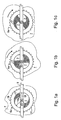
- a phase wheel 6a is shown mounted above a metallic ground plane 7 beneath a stripline 9 of a transmission line feeding an element of an antenna.
- the phase wheel 6a holds a specially shaped dielectric 17 .
- the phase wheel 6a is rotated by means of its gear teeth 21 , more or less of the shaped dielectric 17 is positioned beneath the stripline 9.
- the shaped dielectric 17, in the preferred embodiment is distributed on the phase wheel 6a so that as the phase wheel 6a is rotated, the dielectric beneath the stripline varies directly with an angular displacement (rotation by turning) of the phase wheel, the amount increasing or decreasing depending on the initial and final orientation of the phase wheel.
- phase-shifter of the present invention When the phase-shifter of the present invention is used in an antenna system for broadcasting an RF signal, the electric field of the RF signal to be broadcast is concentrated between the metallic ground plane 7 and the stripline 9 .
- the RF signal When a phase wheel is rotated so that more dielectric is positioned between the stripline and the ground plane, the RF signal is delayed, i.e., it is phase-shifted.
- the phase wheel 6a in the orientation illustrated in Fig. 1a, produces the greatest phase shift since as much dielectric as possible is directly beneath the stripline 9 .
- the phase wheel 6a In the orientation shown in Fig. 1b, the phase wheel 6a produces less phase shift; and the phase wheel 6a in the orientation shown in Fig. 1c produces the least phase shift of the three orientations.
- a phase wheel 6a is made as one piece by injection molding.
- the phase Wheel 6a has an annular ring 16 intended to hold the shaped dielectric 17 and to provide strength enough to rotate the phase wheel by its geared teeth 21 .
- the shaped dielectric 17 is in addition to the dielectric of the annular ring 16, which, in the preferred embodiment, is the same material since the entire phase wheel 6a is injection molded.
- the thickness of the shaped dielectric 17 is approximately three times that of the annular ring 16 .
- phase wheel annular ring 16 is made of material different from the shaped dielectric, and for material that has a dielectric constant near air, the thickness is irrelevant in connection with producing a phase shift.
- the shaped dielectric 17 be sized according to the wavelength of the RF signal in such a way as to reduce or eliminate reflected waves that occur whenever the RF signal encounters a change in impedance, i.e., whenever the RF signal first encounters or leaves the shaped dielectric 17 .
- this is achieved by forming the phase wheel 6a so that not only does it have an outer annular ring 16, but also an inner core 20, with none of the shaped dielectric 17.
- each span of shaped dielectric encountered by the RF signal is one-quarter of a wavelength of the RF signal in that span (or odd integral multiples thereof), then, for a given span, the wave reflected on leaving is 180 degrees out of phase with respect to the wave reflected on entering the span, and the two waves cancel, producing no reflection.
- the distance between the two starting points of the dielectric inside diameter of the annular ring 16 is made to be one eighth the wavelength of the RF signal in whatever material occupies the volume between the stripline 9 and the metallic ground plane 7 outside of the shaped dielectric 17 . In the preferred embodiment, this is air.
- the radius 18a in Fig. 1 should be one-eighth the wavelength of the RF signal in air, because in the preferred embodiment the space outside of the shaped dielectric 17 , between the stripline 9 and the metallic ground plane 7 , is filled with air. (In other embodiments, this space may be filled with other dielectric materials.) In addition, the radius 18 shown in Fig. 1 should be one-quarter of the wavelength of the RF signal in the shaped dielectric 17 .
- the value of the dielectric constant of the shaped dielectric 17 is taken into account.
- the shaped dielectric 17 fits inside the annular ring 16 having a constant inside radius 18a . This occurs only when using a shaped dielectric 17 having a dielectric constant equal to the value 4, because of requiring, in the design of a phase wheel, that the diameter across the inside of the annular ring 16 be one-quarter of a wavelength of the RF signal in air, and also that this same diameter be one-half of the wavelength of the RF signal in the shaped dielectric 17 .
- the shaped dielectric 17 spans a smaller length, as shown in Fig. 3. If the value is less than four, the outer perimeter of the shaped dielectric 17 deforms from circular in the opposite sense, so that it extends beyond the radius at minimum phase shift (radius 18a in Fig. 3).
- the core 20 it is believed also possible to sometimes meet the antenna down-tilt requirements using phase wheels having shaped dielectrics with values other than 4, and yet that are not deformed either as in Fig. 3, or deformed in the opposite sense. This is done by designing the core 20 to vary in diameter so as to compensate for the two-fold requirement that the extent 18 be one-quarter of a wavelength of the RF signal in the dielectric, and that the extent 18a be one-eighth of a wavelength of the RF signal in air. For example, to avoid deforming the shaped dielectric as in Fig. 3, the core 20 would be made larger in the orientation corresponding to maximum phase shift.
- the required dielectric constant K e [ ⁇ /( ⁇ - ⁇ )] 2 in which ⁇ is the maximum phase shift.
- K e 50° (0.87 radians)
- the dielectric constant K e of the shaped dielectric 17 must be approximately 1.92.
- FIG. 2 an assembly of six phase wheels 6a-f , geared to be mechanically synchronized; and all turned by a single drive gear 8 , are shown connected to input feed 11 to feed four elements of a planar antenna array (not shown) through outputs 12-15 , each output feeding a different antenna element.
- the drive gear 8 is itself turned by a stepper motor.
- Each phase wheel 6a-f is fastened to the metallic ground plane 7 using a dielectric fastener 10.
- the RF signal at output 12 is the most phase-shifted because the RF signal encounters the dielectric spanning the entire length of the stripline 9 on top of the left-most phase wheel 6a , and then some additional dielectric beneath the striplme 9 spanning the phase wheel 6b , second from left.
- the RF signal encounters only the shaped dielectric 17 beneath the stripline 9 spanning the phase wheel 6c , and is therefore phase-shifted less than the RF signal arriving at output 12.
- the RF signal at output 14 is the least phase-shifted.
- ⁇ t ⁇ /2 - cos -1 [ ⁇ /(2 ⁇ l )] where l is the antenna element spacing.
- each phase wheel uses a shaped dielectric 17 having a dielectric constant of value 4, and thus each phase wheel produces a maximum phase shift of 90°, and its shaped dielectric 17 is round, in the sense illustrated in Figs. 1a-c and Fig. 2.
- the phase shifter of the present invention can be used in antennas with many different types of radiating elements, and can be used to tilt the radiation patterns of either uni-directional or omni-directional antennas.
- the preferred embodiment uses six phase wheels 6a-f for a four-element planar antenna
- the present invention is not limited to using six phase wheels for a four-element array, and is not limited to use with an antenna having four elements.
- this arrangement for continuously varying the phase shift of an antenna element can be used in an antenna system using a feed system that is series, binary, or any combination of series and binary feed systems.
- shaped dielectric 17 is formed to provide a linear relation between rotation and amount of dielectric beneath the stripline 9
- shape can be varied to produce other kinds of relationship.
- a phase wheel according to the present invention can be fabricated from any type of dielectric material, including but not limited to plastic, ceramic and composite material.
- phase-shifter of the present invention could be used with equal advantage in either a broadcast or receiver communication system.
Landscapes
- Variable-Direction Aerials And Aerial Arrays (AREA)
- Waveguide Switches, Polarizers, And Phase Shifters (AREA)
Claims (5)
- Un déphaseur capable de faire varier en continu l'inclinaison vers le bas d'un diagramme de rayonnement associé à une antenne pour un signal radiofréquence, l'antenne comportant une pluralité d'éléments d'antenne et ayant un terminal d'élément pour chaque élément d'antenne et disposant en plus d'un système d'alimentation pour communiquer le signal radiofréquence entre chaque terminal d'élément et un terminal d'alimentation commun, le système d'alimentation incluant une barrette conductrice espacée au-dessus d'un plan de masse métallique, et disposant en plus d'une roue de phase avec un diélectrique de forme réparti à l'intérieur du diamètre intérieur de la roue et positionné de façon à pouvoir tourner entre le plan de masse métallique et la barrette conductrice de sorte qu'en fonction de l'orientation de la roue de phase correspondant à la barrette conductrice, une quantité particulière de diélectrique se trouve directement en dessous de la barrette conductrice et au-dessus du plan de masse métallique ; il est ainsi possible d'utiliser différents moyens pour faire tourner la roue de phase correspondant à la barrette conductrice, la quantité de diélectrique se trouvant directement en dessous de la barrette conductrice et au-dessus du plan de masse métallique. caractérisé parle fait que plusieurs roues de phase (6a à f) sont fournies, chacune ayant un diélectrique de forme (17) réparti à l'intérieur du diamètre intérieur de la roue, et chacune positionnée de sorte à pouvoir tourner entre le plan de masse métallique (7) et la barrette conductrice (9) où chaque roue de phase (6a à f) est engagée avec au moins une des autres roues de phase de façon à l'entraíner dans une disposition telle que toutes les roues de phase (6a à f) sont couplées de façon à s'entraíner mutuellement ; etque des moyens (8) pour faire tourner l'une des roues de phase (6a à f) relative à la barrette conductrice (9) soient fournis, où toutes les roues de phase (6a à f) sont tournées de façon synchrone, chacune faisant varier, quand on la fait tourner, la quantité de diélectrique sous la barrette conductrice (9), provoquant ainsi la variation de tout le diagramme de rayonnement dans son inclinaison vers le bas, la variation du diagramme de rayonnement global dans son l'inclinaison vers le bas étant ainsi produite par un mouvement mécanique purement rotatif.
- Un déphaseur selon la revendication 1, caractérisé par le fait que sur chaque roue de phase (6a à f), le diélectrique de forme (17) est réparti de sorte que lorsque n'importe laquelle des roues de phase (6a à f) est tournée, la quantité de diélectrique directement sous la barrette conductrice (9) et entre la barrette conductrice (9) et le plan de masse métallique (7) évolue de façon directement proportionnelle au déplacement angulaire de la roue de phase (6a à f).
- Un déphaseur selon la revendication 1, caractérisé par le fait que le diélectrique de forme (17) est choisi pour avoir une constante diélectrique donnée par :
- Un déphaseur selon la revendication 1, caractérisé par le fait que le diélectrique de forme (17) est réparti sur chaque roue de phase (6a à f) de sorte que lorsqu'une ou plusieurs roue(s) de phase (6a à f) est/sont orientée(s) pour un déphasage maximum, en positionnant au moins une plage du diélectrique de forme (17) directement au-dessous de la barrette conductrice (9), au moins une plage du diélectrique de forme (17) s'étend directement sous la barrette conductrice (9) sur une longueur égale à un multiple entier impair d'un quart de la longueur d'onde du signal radiofréquence dans le diélectrique de forme (17), produisant ainsi une annulation mutuelle des deux ondes réfléchies produites alors que le signal radiofréquence traverse la plage du diélectrique de forme (17).
- Un déphaseur selon la revendication 1, caractérisé par le fait que le diélectrique de forme (17) est réparti sur chaque roue de phase (6a à f) de sorte que lorsqu'une ou plusieurs roue(s) de phase (6a à f) est/sont orientée(s) pour un déphasage minimum au moins deux plages du diélectrique de forme (17) sont positionnées pour être déplacées directement sous la barrette conductrice (9) par une légère rotation ultérieure des roues de phase (6a à f), et sont séparées par une matière ayant approximativement la même constante diélectrique que l'air, s'étendant directement au-dessous de la barrette conductrice (9) sur une longueur égale à un multiple entier impair d'un quart de la longueur d'onde du signal radiofréquence dans la matière.
Applications Claiming Priority (2)
| Application Number | Priority Date | Filing Date | Title |
|---|---|---|---|
| US08/805,589 US5798675A (en) | 1997-02-25 | 1997-02-25 | Continuously variable phase-shifter for electrically down-tilting an antenna |
| US805589 | 1997-02-25 |
Publications (2)
| Publication Number | Publication Date |
|---|---|
| EP0860890A1 EP0860890A1 (fr) | 1998-08-26 |
| EP0860890B1 true EP0860890B1 (fr) | 2003-01-08 |
Family
ID=25191979
Family Applications (1)
| Application Number | Title | Priority Date | Filing Date |
|---|---|---|---|
| EP98400302A Expired - Lifetime EP0860890B1 (fr) | 1997-02-25 | 1998-02-09 | Déphaseur à variation continue pour incliner électriquement une antenne |
Country Status (8)
| Country | Link |
|---|---|
| US (1) | US5798675A (fr) |
| EP (1) | EP0860890B1 (fr) |
| JP (1) | JPH10276004A (fr) |
| KR (1) | KR100458094B1 (fr) |
| AU (1) | AU728595B2 (fr) |
| CA (1) | CA2220745A1 (fr) |
| DE (1) | DE69810523T2 (fr) |
| ES (1) | ES2191262T3 (fr) |
Families Citing this family (45)
| Publication number | Priority date | Publication date | Assignee | Title |
|---|---|---|---|---|
| CN1316835C (zh) | 1994-11-04 | 2007-05-16 | 安德鲁公司 | 天线控制系统 |
| US6900775B2 (en) | 1997-03-03 | 2005-05-31 | Celletra Ltd. | Active antenna array configuration and control for cellular communication systems |
| EP1012994A1 (fr) | 1997-03-03 | 2000-06-28 | Celletra Ltd. | Systemes de telecommunications cellulaires |
| US6097969A (en) * | 1997-12-31 | 2000-08-01 | Weblink Wireless, Inc, | System for scheduling reverse-channel messages in narrowband communications systems and methods of operation |
| US6097970A (en) * | 1997-12-31 | 2000-08-01 | Weblink Wireless, Inc. | Antenna system for narrowband communications systems and method of operation |
| US5905462A (en) * | 1998-03-18 | 1999-05-18 | Lucent Technologies, Inc. | Steerable phased-array antenna with series feed network |
| US6667714B1 (en) * | 2000-05-03 | 2003-12-23 | Lucent Technologies Inc. | Downtilt control for multiple antenna arrays |
| KR20090033403A (ko) | 2000-07-10 | 2009-04-02 | 앤드류 코포레이션 | 셀룰러 안테나 |
| KR100563565B1 (ko) * | 2000-11-03 | 2006-03-28 | 주식회사 케이엠더블유 | 안테나 |
| KR100374175B1 (ko) * | 2000-12-29 | 2003-03-03 | 주식회사 에이스테크놀로지 | 틸팅각 조정이 가능한 기지국용 배열 안테나 |
| DE10104564C1 (de) | 2001-02-01 | 2002-09-19 | Kathrein Werke Kg | Steuerungsvorrichtung zum Einstellen eines unterschiedlichen Absenkwinkels insbesondere von zu einer Basisstation gehörenden Mobilfunkantennen sowie eine zugehörige Antenne und Verfahren zur Veränderung eines Absenkwinkels |
| US6573875B2 (en) | 2001-02-19 | 2003-06-03 | Andrew Corporation | Antenna system |
| DE20216431U1 (de) | 2001-02-19 | 2003-03-13 | Andrew Corp., Orland Park, Ill. | Antenne einer Zellularbasisstation |
| US6717555B2 (en) * | 2001-03-20 | 2004-04-06 | Andrew Corporation | Antenna array |
| US7639196B2 (en) | 2001-07-10 | 2009-12-29 | Andrew Llc | Cellular antenna and systems and methods therefor |
| WO2003019720A1 (fr) * | 2001-08-23 | 2003-03-06 | Ems Technologies, Inc. | Dephaseur microruban |
| NZ513770A (en) * | 2001-08-24 | 2004-05-28 | Andrew Corp | Adjustable antenna feed network with integrated phase shifter |
| GB0125345D0 (en) * | 2001-10-22 | 2001-12-12 | Qinetiq Ltd | Antenna System |
| GB0125349D0 (en) * | 2001-10-22 | 2001-12-12 | Qinetiq Ltd | Antenna system |
| US7274331B2 (en) * | 2001-12-03 | 2007-09-25 | Huber + Suhner Ag | Phase-shifting system using a displaceable dielectric and phase array antenna comprising such a phase-shifting system |
| GB0200585D0 (en) * | 2002-01-11 | 2002-02-27 | Csa Ltd | Antenna with adjustable beam direction |
| WO2003083992A1 (fr) * | 2002-03-26 | 2003-10-09 | Andrew Corp. | Antenne multi-bande de station de base reglable, a faisceau incline et a double polarisation |
| US6963314B2 (en) * | 2002-09-26 | 2005-11-08 | Andrew Corporation | Dynamically variable beamwidth and variable azimuth scanning antenna |
| US6809694B2 (en) * | 2002-09-26 | 2004-10-26 | Andrew Corporation | Adjustable beamwidth and azimuth scanning antenna with dipole elements |
| CN1720636A (zh) * | 2002-11-08 | 2006-01-11 | Ems技术公司 | 可变功率分配器 |
| US7221239B2 (en) * | 2002-11-08 | 2007-05-22 | Andrew Corporation | Variable power divider |
| US6924776B2 (en) * | 2003-07-03 | 2005-08-02 | Andrew Corporation | Wideband dual polarized base station antenna offering optimized horizontal beam radiation patterns and variable vertical beam tilt |
| US7358922B2 (en) * | 2002-12-13 | 2008-04-15 | Commscope, Inc. Of North Carolina | Directed dipole antenna |
| KR100653937B1 (ko) | 2003-05-23 | 2006-12-08 | 주식회사 케이엠더블유 | 안테나 시스템에 채용되는 안테나 어레이 빔 가변용 구동장치 |
| US7427962B2 (en) | 2003-06-16 | 2008-09-23 | Andrew Corporation | Base station antenna rotation mechanism |
| US8018390B2 (en) | 2003-06-16 | 2011-09-13 | Andrew Llc | Cellular antenna and systems and methods therefor |
| WO2006085152A2 (fr) * | 2004-04-30 | 2006-08-17 | Ems Technologies, Inc. | Antennes a accord variable |
| US7557675B2 (en) * | 2005-03-22 | 2009-07-07 | Radiacion Y Microondas, S.A. | Broad band mechanical phase shifter |
| CN2812316Y (zh) * | 2005-06-02 | 2006-08-30 | 京信通信技术(广州)有限公司 | 用于移动通信天线移相器的调整装置 |
| FI20055285A7 (fi) * | 2005-06-03 | 2006-12-04 | Filtronic Comtek Oy | Tukiasema-antennin syöttöjärjestely |
| CN1332175C (zh) * | 2005-08-23 | 2007-08-15 | 广州杰赛科技股份有限公司 | 通信天线电下倾角度的检测装置及检测方法 |
| CN101553955B (zh) | 2006-10-16 | 2013-10-23 | 艾利森电话股份有限公司 | 倾斜相关的波束形状系统 |
| KR100894994B1 (ko) * | 2007-10-05 | 2009-04-24 | (주)에이스안테나 | 회전 부재와 가이드 부재가 결합되는 구조를 가지는 페이즈쉬프터 |
| US10199725B2 (en) | 2013-11-12 | 2019-02-05 | Alcatel-Lucent Shanghai Bell Co., Ltd. | Methods and devices for reducing passive intermodulation in RF antennas |
| US10033086B2 (en) * | 2014-11-10 | 2018-07-24 | Commscope Technologies Llc | Tilt adapter for diplexed antenna with semi-independent tilt |
| CN110504511B (zh) * | 2018-05-16 | 2022-04-05 | 康普技术有限责任公司 | 用于移相器组件的联动机构 |
| CN108879035B (zh) * | 2018-06-28 | 2021-11-23 | 京信通信技术(广州)有限公司 | 介质滑动式移相器及基站天线 |
| CN110661081B (zh) * | 2018-06-29 | 2023-10-31 | 康普技术有限责任公司 | 包括接帚移相器的基站天线 |
| CN111490317B (zh) * | 2020-05-14 | 2025-01-24 | 京信通信技术(广州)有限公司 | 介质滑动型移相器及基站天线 |
| CN112883551B (zh) * | 2021-01-19 | 2023-05-16 | 贵州电网有限责任公司 | 一种基于点云数据的输电线路连续档安全系数反算方法 |
Family Cites Families (13)
| Publication number | Priority date | Publication date | Assignee | Title |
|---|---|---|---|---|
| GB767067A (en) * | 1955-01-26 | 1957-01-30 | Standard Telephones Cables Ltd | Microwave transmission line phase shifter |
| US3005168A (en) * | 1959-10-08 | 1961-10-17 | David L Fye | Microwave phase shifter |
| US3139597A (en) * | 1960-12-08 | 1964-06-30 | Sylvania Electric Prod | Adjustable microwave phase shifter using stripling having variable dielectric |
| US3114121A (en) * | 1961-09-25 | 1963-12-10 | Lab For Electronics Inc | Microwave phase shifter |
| US3181091A (en) * | 1962-04-02 | 1965-04-27 | Bendix Corp | Microwave phase shifter |
| US3946396A (en) * | 1974-03-06 | 1976-03-23 | The Magnavox Company | Antenna for providing a dielectrically induced, directionally dependent radiation pattern phase shift |
| US4129872A (en) * | 1976-11-04 | 1978-12-12 | Tull Aviation Corporation | Microwave radiating element and antenna array including linear phase shift progression angular tilt |
| FR2706680B1 (fr) * | 1986-07-04 | 1995-09-01 | Onera (Off Nat Aerospatiale) | Déphaseur hyperfréquence à microruban et diélectrique suspendu, et application à des réseaux d'antennes à balayage de lobe. |
| US5281974A (en) * | 1988-01-11 | 1994-01-25 | Nec Corporation | Antenna device capable of reducing a phase noise |
| SU1707661A1 (ru) * | 1989-02-13 | 1992-01-23 | Организация П/Я В-8942 | Фазовращатель |
| FR2662026B1 (fr) * | 1990-05-11 | 1992-07-10 | Thomson Csf | Antenne orientable plane, fonctionnant en micro-ondes. |
| US5343173A (en) * | 1991-06-28 | 1994-08-30 | Mesc Electronic Systems, Inc. | Phase shifting network and antenna and method |
| CA2097122A1 (fr) * | 1992-06-08 | 1993-12-09 | James Hadzoglou | Antenne a faisceau a inclinaison ajustable |
-
1997
- 1997-02-25 US US08/805,589 patent/US5798675A/en not_active Expired - Lifetime
- 1997-12-01 CA CA002220745A patent/CA2220745A1/fr not_active Abandoned
- 1997-12-15 KR KR1019970068709A patent/KR100458094B1/ko not_active Expired - Fee Related
-
1998
- 1998-02-09 DE DE69810523T patent/DE69810523T2/de not_active Expired - Lifetime
- 1998-02-09 EP EP98400302A patent/EP0860890B1/fr not_active Expired - Lifetime
- 1998-02-09 ES ES98400302T patent/ES2191262T3/es not_active Expired - Lifetime
- 1998-02-19 AU AU55373/98A patent/AU728595B2/en not_active Ceased
- 1998-02-25 JP JP10043895A patent/JPH10276004A/ja active Pending
Also Published As
| Publication number | Publication date |
|---|---|
| US5798675A (en) | 1998-08-25 |
| DE69810523T2 (de) | 2003-10-02 |
| KR19980070160A (ko) | 1998-10-26 |
| AU5537398A (en) | 1999-09-16 |
| EP0860890A1 (fr) | 1998-08-26 |
| ES2191262T3 (es) | 2003-09-01 |
| AU728595B2 (en) | 2001-01-11 |
| CA2220745A1 (fr) | 1998-08-25 |
| DE69810523D1 (de) | 2003-02-13 |
| KR100458094B1 (ko) | 2005-01-31 |
| JPH10276004A (ja) | 1998-10-13 |
Similar Documents
| Publication | Publication Date | Title |
|---|---|---|
| EP0860890B1 (fr) | Déphaseur à variation continue pour incliner électriquement une antenne | |
| AU2003208992B2 (en) | Aperiodic array antenna | |
| US4123759A (en) | Phased array antenna | |
| US5220340A (en) | Directional switched beam antenna | |
| US5281974A (en) | Antenna device capable of reducing a phase noise | |
| EP3716405B1 (fr) | Polariseur linéaire à cp à performances améliorées dans les antennes victs | |
| EP1196962B1 (fr) | Antenne syntonisable en spirale | |
| WO2020154667A1 (fr) | Systèmes d'antenne de couverture sphérique, dispositifs et procédés | |
| WO2006015215A9 (fr) | Antenne intelligente a large bande et procedes associes | |
| US6067058A (en) | End-fed spiral antenna, and arrays thereof | |
| US7019703B2 (en) | Antenna with Rotatable Reflector | |
| US20060145784A1 (en) | Phase shifter device | |
| US20090195329A1 (en) | Variable phase shifter | |
| CN101473489A (zh) | 可变移相器 | |
| GB2480548A (en) | Phase Shifter Element for adjusting a transmission phase | |
| CN114614270B (zh) | 一种基于可重构的双极化反射表面天线 | |
| EP1870959B1 (fr) | Dephaseur mecanique a bande large | |
| EP4178039B1 (fr) | Antenne à faisceau à orientation électronique du type espar | |
| Dey et al. | Novel FSS Based Multibit Passive 8× 8 RIS for NextGen Wireless Communication | |
| WO1993000724A1 (fr) | Antenne active a microbande integree | |
| WO2001039322A1 (fr) | Dispositif de pointage de faisceau utilisant un reseau de terre a largeur de bande interdite photonique de type a structure reconfigurable | |
| WO2002084797A1 (fr) | Antenne | |
| AU2007201112A1 (en) | Aperiodic array antenna | |
| JP2000031733A (ja) | 偏波切換アンテナ装置 | |
| JPH02192204A (ja) | 円偏波アンテナ |
Legal Events
| Date | Code | Title | Description |
|---|---|---|---|
| PUAI | Public reference made under article 153(3) epc to a published international application that has entered the european phase |
Free format text: ORIGINAL CODE: 0009012 |
|
| AK | Designated contracting states |
Kind code of ref document: A1 Designated state(s): DE ES FR GB IE IT SE |
|
| AX | Request for extension of the european patent |
Free format text: AL;LT;LV;MK;RO;SI |
|
| 17P | Request for examination filed |
Effective date: 19980811 |
|
| AKX | Designation fees paid |
Free format text: DE ES FR GB IE IT SE |
|
| RBV | Designated contracting states (corrected) |
Designated state(s): DE ES FR GB IE IT SE |
|
| 17Q | First examination report despatched |
Effective date: 20011126 |
|
| GRAH | Despatch of communication of intention to grant a patent |
Free format text: ORIGINAL CODE: EPIDOS IGRA |
|
| GRAH | Despatch of communication of intention to grant a patent |
Free format text: ORIGINAL CODE: EPIDOS IGRA |
|
| GRAA | (expected) grant |
Free format text: ORIGINAL CODE: 0009210 |
|
| AK | Designated contracting states |
Kind code of ref document: B1 Designated state(s): DE ES FR GB IE IT SE |
|
| REG | Reference to a national code |
Ref country code: GB Ref legal event code: FG4D |
|
| REG | Reference to a national code |
Ref country code: IE Ref legal event code: FG4D |
|
| PG25 | Lapsed in a contracting state [announced via postgrant information from national office to epo] |
Ref country code: IE Free format text: LAPSE BECAUSE OF NON-PAYMENT OF DUE FEES Effective date: 20030210 |
|
| REF | Corresponds to: |
Ref document number: 69810523 Country of ref document: DE Date of ref document: 20030213 Kind code of ref document: P |
|
| PG25 | Lapsed in a contracting state [announced via postgrant information from national office to epo] |
Ref country code: SE Free format text: LAPSE BECAUSE OF FAILURE TO SUBMIT A TRANSLATION OF THE DESCRIPTION OR TO PAY THE FEE WITHIN THE PRESCRIBED TIME-LIMIT Effective date: 20030408 |
|
| REG | Reference to a national code |
Ref country code: ES Ref legal event code: FG2A Ref document number: 2191262 Country of ref document: ES Kind code of ref document: T3 |
|
| ET | Fr: translation filed | ||
| PLBE | No opposition filed within time limit |
Free format text: ORIGINAL CODE: 0009261 |
|
| STAA | Information on the status of an ep patent application or granted ep patent |
Free format text: STATUS: NO OPPOSITION FILED WITHIN TIME LIMIT |
|
| REG | Reference to a national code |
Ref country code: IE Ref legal event code: MM4A |
|
| 26N | No opposition filed |
Effective date: 20031009 |
|
| REG | Reference to a national code |
Ref country code: FR Ref legal event code: TP Owner name: ALCATEL LUCENT, FR Effective date: 20130628 |
|
| REG | Reference to a national code |
Ref country code: GB Ref legal event code: 732E Free format text: REGISTERED BETWEEN 20130822 AND 20130828 |
|
| REG | Reference to a national code |
Ref country code: FR Ref legal event code: GC Effective date: 20130920 |
|
| REG | Reference to a national code |
Ref country code: FR Ref legal event code: RG Effective date: 20141016 |
|
| REG | Reference to a national code |
Ref country code: FR Ref legal event code: PLFP Year of fee payment: 18 |
|
| REG | Reference to a national code |
Ref country code: FR Ref legal event code: PLFP Year of fee payment: 19 |
|
| PGFP | Annual fee paid to national office [announced via postgrant information from national office to epo] |
Ref country code: IT Payment date: 20160223 Year of fee payment: 19 Ref country code: ES Payment date: 20160210 Year of fee payment: 19 Ref country code: DE Payment date: 20160218 Year of fee payment: 19 |
|
| PGFP | Annual fee paid to national office [announced via postgrant information from national office to epo] |
Ref country code: FR Payment date: 20160218 Year of fee payment: 19 Ref country code: GB Payment date: 20160217 Year of fee payment: 19 |
|
| REG | Reference to a national code |
Ref country code: DE Ref legal event code: R119 Ref document number: 69810523 Country of ref document: DE |
|
| GBPC | Gb: european patent ceased through non-payment of renewal fee |
Effective date: 20170209 |
|
| REG | Reference to a national code |
Ref country code: FR Ref legal event code: ST Effective date: 20171031 |
|
| PG25 | Lapsed in a contracting state [announced via postgrant information from national office to epo] |
Ref country code: FR Free format text: LAPSE BECAUSE OF NON-PAYMENT OF DUE FEES Effective date: 20170228 Ref country code: DE Free format text: LAPSE BECAUSE OF NON-PAYMENT OF DUE FEES Effective date: 20170901 |
|
| PG25 | Lapsed in a contracting state [announced via postgrant information from national office to epo] |
Ref country code: GB Free format text: LAPSE BECAUSE OF NON-PAYMENT OF DUE FEES Effective date: 20170209 Ref country code: IT Free format text: LAPSE BECAUSE OF NON-PAYMENT OF DUE FEES Effective date: 20170209 |
|
| REG | Reference to a national code |
Ref country code: ES Ref legal event code: FD2A Effective date: 20180507 |
|
| PG25 | Lapsed in a contracting state [announced via postgrant information from national office to epo] |
Ref country code: ES Free format text: LAPSE BECAUSE OF NON-PAYMENT OF DUE FEES Effective date: 20170210 |