EP0861705A2 - Calotte de meulage - Google Patents
Calotte de meulage Download PDFInfo
- Publication number
- EP0861705A2 EP0861705A2 EP98106796A EP98106796A EP0861705A2 EP 0861705 A2 EP0861705 A2 EP 0861705A2 EP 98106796 A EP98106796 A EP 98106796A EP 98106796 A EP98106796 A EP 98106796A EP 0861705 A2 EP0861705 A2 EP 0861705A2
- Authority
- EP
- European Patent Office
- Prior art keywords
- wear part
- passageway
- grinding
- grinding cup
- disposed
- Prior art date
- Legal status (The legal status is an assumption and is not a legal conclusion. Google has not performed a legal analysis and makes no representation as to the accuracy of the status listed.)
- Ceased
Links
Images
Classifications
-
- E—FIXED CONSTRUCTIONS
- E21—EARTH OR ROCK DRILLING; MINING
- E21B—EARTH OR ROCK DRILLING; OBTAINING OIL, GAS, WATER, SOLUBLE OR MELTABLE MATERIALS OR A SLURRY OF MINERALS FROM WELLS
- E21B10/00—Drill bits
- E21B10/46—Drill bits characterised by wear resisting parts, e.g. diamond inserts
- E21B10/56—Button-type inserts
-
- B—PERFORMING OPERATIONS; TRANSPORTING
- B24—GRINDING; POLISHING
- B24B—MACHINES, DEVICES, OR PROCESSES FOR GRINDING OR POLISHING; DRESSING OR CONDITIONING OF ABRADING SURFACES; FEEDING OF GRINDING, POLISHING, OR LAPPING AGENTS
- B24B3/00—Sharpening cutting edges, e.g. of tools; Accessories therefor, e.g. for holding the tools
- B24B3/24—Sharpening cutting edges, e.g. of tools; Accessories therefor, e.g. for holding the tools of drills
- B24B3/33—Sharpening cutting edges, e.g. of tools; Accessories therefor, e.g. for holding the tools of drills of drills for stone
-
- B—PERFORMING OPERATIONS; TRANSPORTING
- B24—GRINDING; POLISHING
- B24B—MACHINES, DEVICES, OR PROCESSES FOR GRINDING OR POLISHING; DRESSING OR CONDITIONING OF ABRADING SURFACES; FEEDING OF GRINDING, POLISHING, OR LAPPING AGENTS
- B24B3/00—Sharpening cutting edges, e.g. of tools; Accessories therefor, e.g. for holding the tools
- B24B3/60—Sharpening cutting edges, e.g. of tools; Accessories therefor, e.g. for holding the tools of tools not covered by the preceding subgroups
-
- B—PERFORMING OPERATIONS; TRANSPORTING
- B24—GRINDING; POLISHING
- B24B—MACHINES, DEVICES, OR PROCESSES FOR GRINDING OR POLISHING; DRESSING OR CONDITIONING OF ABRADING SURFACES; FEEDING OF GRINDING, POLISHING, OR LAPPING AGENTS
- B24B55/00—Safety devices for grinding or polishing machines; Accessories fitted to grinding or polishing machines for keeping tools or parts of the machine in good working condition
- B24B55/02—Equipment for cooling the grinding surfaces, e.g. devices for feeding coolant
-
- B—PERFORMING OPERATIONS; TRANSPORTING
- B24—GRINDING; POLISHING
- B24D—TOOLS FOR GRINDING, BUFFING OR SHARPENING
- B24D7/00—Bonded abrasive wheels, or wheels with inserted abrasive blocks, designed for acting otherwise than only by their periphery, e.g. by the front face; Bushings or mountings therefor
- B24D7/10—Bonded abrasive wheels, or wheels with inserted abrasive blocks, designed for acting otherwise than only by their periphery, e.g. by the front face; Bushings or mountings therefor with cooling provisions
Definitions
- the present invention relates to a grinding cup and a wear part for grinding buttons of a rock drilling bit according to the preambles of the appended independent claims.
- a grinding cup of the type described above When grinding cemented carbide buttons of a drill bit, a grinding cup of the type described above is normally used.
- the wear part of such grinding cup usually has an abrasive grinding surface that often includes granular diamond.
- the grinding of cemented carbide buttons generates both heat and abrasive cuttings to such an extent that it is necessary to cool the grinding cup and the button bit as well as to flush away the cuttings.
- the known prior art technique for such cooling is to supply cooling medium, normally water, through the grinding machine and axially through the grinding cup to provide the cooling medium to be discharged in the region where the wear part of the grinding cup engages the free end of the button.
- An object of the present invention is to provide a grinding cup for grinding of rock drill bit buttons, configured such that the active surface of the button becomes smooth after grinding and such that the button is sufficiently cooled. Furthermore the configuration of the grinding cup according to the present invention makes it possible to increase the volume of abrasive material in the wear part of the grinding cup. The objects of the present invention are realized by a grinding cup and a wear part that have been given the characteristics of the appended claims.
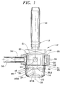
- FIG. 1 shows a partly sectioned side view of a grinding cup according to the present invention.
- the grinding cup 10 includes a shank 12, a wear part 14 and an intermediate portion 16 that is integrally connected with both the shank 12 and the wear part 14.
- the shank 12 is provided with a groove 13 that is intended to receive an O-ring that yieldably secures the shank 12 when mounted in the grinding machine.
- the shank 12 and the intermediate portion 16 are in one piece.
- the wear part 14 is connected to the intermediate portion 16 in a suitable way, preferably by brazing. However, within the present invention it is also possible that the wear part 14 is integral with the intermediate portion 16.
- the grinding cup 10' is symmetrical as of rotation relative to its longitudinal centre axis 18.
- the free end of the wear part 14 has a recess 20 in the shape of a segment of a sphere.
- the shape of the recess can however vary depending on the shape of the free end of the button.
- the recess 20 is intended to engage and cooperate with the free end of a button that is subjected to grinding.
- the button is preferably made out of cemented carbide and the recess 20 is equipped with an abrasive material, preferably diamond that can be in the shape of a matrix, electro-plated to a steel body or in some other way adhered to the steel body.
- the intermediate portion 16 of the grinding cup 10' is provided with a key handle 19 that cooperates with driving means of the grinding machine to rotate the grinding cup 10'.
- the intermediate portion 16 of the grinding cup 10' is further provided with a circumferential external flange 21 that separates the key handle 19 from a sub-portion 22 of the intermediate portion 16, the key handle 19 and the sub-portion 22 having different diameters.
- the sub-portion 22 having smaller diameter has a certain extension in axial direction of the grinding cup 10', said extension being defined by a circumferential slot 23.
- Preferably the external diameter of the sub-portion 22 is constant.
- a first hole 24, having radial direction, extends between the periphery of the sub-portion 22 and the region of the longitudinal centre axis 18.
- the first and second holes 24 26 are connected with each other in the area of their inner ends.
- a passageway or a third hole 27 extends from the region of the downstream end 26A of the second hole 26, said third hole 27 emanating in the recess 20.
- the third hole 27 is displaced in radial direction relative to the second hole 26 although the second and third holes 26, 27 are hydraulically communicating with each other via a means 40.
- the third hole 27 emanates eccentrically in the recess 20. In this connection it should be pointed out that the design and orientation of especially the third hole 27 can vary within the scope of the present invention.
- the upstream channel portion 26 is disposed upstream of the wear part and a wear part channel portion 27 provides a passageway through said wear part.
- the passageway is disposed between the downstream end 26A of the upstream channel portion and the cavity 20.
- the means 40 is provided to hydraulically communicate said upstream channel portion 26 with the passageway.
- the passageway is so disposed and arranged relative to the axis 18 of rotation of the grinding cup that the downstream end 27A of the passageway disposed in said cavity is displaced radially outwardly relative to the axis 18.
- a radially innermost part and a radially outermost part of the downstream end 27A of the passageway 27 are both located to the same side of and at a distance radially outwardly from the axis 18.
- a first washer 29, a ring 28 of flexible material, e.g. plastic or rubber, and a second washer 31 are mounted in consecutive order.
- the first washer 29 is in close contact with the flange 21.
- the total height of the first washer 29, the ring 28 and the second washer 31 is somewhat smaller than the axial extension of the sub-portion 22.
- a locking ring 25 is mounted to secure the first washer 29, the ring 28 and the second washer 31 in axial direction.
- the inner periphery of the ring 28 is provided with a circumferential internal groove 30. In its mounted position the ring 28 covers the opening of the hole 24.
- the tolerances of the cooperating dimensions of the ring 28 and the sub-portion 22 are adapted to each other, i.e. the internal diameter of the ring 28 and the external diameter of the sub-portion 22.
- the sub-portion 22 must rotate relatively easy relative to the ring 28 and still there must be a proper sealing action between the ring 28 and the sub-portion 22 to guide cooling medium to the recess 20 via the holes 24,26,27.
- the ring 28 is also provided with a pipe 34 that extends in radial direction of the grinding cup 10'.
- the pipe 34 extends through the wall of the ring 28, said pipe 34 being connected to the ring 28 preferably by vulcanization.
- the pipe 34 extends beyond the outer periphery of the ring 28 to a certain extent in order to be able to receive a hose 36, that is pushed onto the pipe 34.
- the pipe 34 can be provided with a bulge to achieve a better securing of the hose 36 on the pipe 34.
- the described grinding cup 10 functions in the following way.
- the grinding cup 10 is mounted in the rotatable spindle of a grinding machine.
- the grinding cup is then adjusted in position relative to the button that is to be ground, i.e. a position where the wear part 14 engages the button.
- the grinding cup 10 is then rotated to perform grinding of the button.
- the grinding cup 10 rotates the ring 28 remains stationary.
- the dimensions and mutual tolerances of the groove 22 and the ring 28 are such that the intermediate portion easily 16 can rotate relative to the ring 28, the supply of cooling medium still being effected. Due to the flexibility of the ring 28 it is possible to mount the ring 28 in the groove 22 by pushing the ring 28 over the wear part 14 into the groove 22.
- the tongues 32 will deflect to allow such pushing of the ring 28 over the wear part 14.
- the space between the sub-portion 22 and the groove 30 is pressurized by cooling medium then the remaining portions 33 of the inner periphery of the ring 28 are urged apart in opposite directions to provide a sealing against the first and second washers 29, 31.
- the first washer 29 is in its turn urged against the flange 21 to provide a sealing against the cooling medium and the second washer 31 is urged against the locking ring 25 to provide a corresponding sealing.
- cooling medium is supplied to the recess 20 via the hose 36, the pipe 34, the groove 30, the first hole 24 and the second hole 26.
- the tongues 30 of the ring 28 seal against the bottom of the groove 22 and simultaneously the side walls of the ring 28 are supported by the side walls of the groove 22.
- this sealing is no definite requirement that this sealing is total. If there is a certain leakage of cooling medium between the tongues 30 of the ring 28 and the bottom of the groove 22, said cooling medium will flow downwards and cool the outside of the wear part 14. Such a cooling is normally favorable in a present grinding action. However, the dominating part of the cooling medium should be supplied via the holes 24 and 26.
- the length of life of the ring 28 is substantially the same as the length of life of the rest of the grinding cup 10 .
- buttons can be ground without the formation of a wart on the button top, which reduces the risk for premature breakage of the button.
- By providing an eccentric flush channel in the wear part the advantages of good cooling and optimal volume of abrasive material are achieved.
Landscapes
- Engineering & Computer Science (AREA)
- Mechanical Engineering (AREA)
- Geology (AREA)
- Life Sciences & Earth Sciences (AREA)
- Mining & Mineral Resources (AREA)
- Environmental & Geological Engineering (AREA)
- Fluid Mechanics (AREA)
- Physics & Mathematics (AREA)
- General Life Sciences & Earth Sciences (AREA)
- Geochemistry & Mineralogy (AREA)
- Polishing Bodies And Polishing Tools (AREA)
- Grinding-Machine Dressing And Accessory Apparatuses (AREA)
- Finish Polishing, Edge Sharpening, And Grinding By Specific Grinding Devices (AREA)
- Earth Drilling (AREA)
- Grinding And Polishing Of Tertiary Curved Surfaces And Surfaces With Complex Shapes (AREA)
Applications Claiming Priority (3)
| Application Number | Priority Date | Filing Date | Title |
|---|---|---|---|
| SE9302160A SE501695C2 (sv) | 1993-06-22 | 1993-06-22 | Förfarande för tillförsel av kylmedel till en slipkopp samt slipkopp för att utföra förfarandet |
| SE9302160 | 1993-06-22 | ||
| EP94919938A EP0706437B1 (fr) | 1993-06-22 | 1994-06-17 | Procede d'alimentation de meules boisseaux en milieu de refroidissement et meule boisseau de mise en uvre du procede |
Related Parent Applications (1)
| Application Number | Title | Priority Date | Filing Date |
|---|---|---|---|
| EP94919938A Division EP0706437B1 (fr) | 1993-06-22 | 1994-06-17 | Procede d'alimentation de meules boisseaux en milieu de refroidissement et meule boisseau de mise en uvre du procede |
Publications (2)
| Publication Number | Publication Date |
|---|---|
| EP0861705A2 true EP0861705A2 (fr) | 1998-09-02 |
| EP0861705A3 EP0861705A3 (fr) | 2000-11-15 |
Family
ID=20390379
Family Applications (2)
| Application Number | Title | Priority Date | Filing Date |
|---|---|---|---|
| EP94919938A Expired - Lifetime EP0706437B1 (fr) | 1993-06-22 | 1994-06-17 | Procede d'alimentation de meules boisseaux en milieu de refroidissement et meule boisseau de mise en uvre du procede |
| EP98106796A Ceased EP0861705A3 (fr) | 1993-06-22 | 1994-06-17 | Calotte de meulage |
Family Applications Before (1)
| Application Number | Title | Priority Date | Filing Date |
|---|---|---|---|
| EP94919938A Expired - Lifetime EP0706437B1 (fr) | 1993-06-22 | 1994-06-17 | Procede d'alimentation de meules boisseaux en milieu de refroidissement et meule boisseau de mise en uvre du procede |
Country Status (12)
| Country | Link |
|---|---|
| US (1) | US5637037A (fr) |
| EP (2) | EP0706437B1 (fr) |
| JP (1) | JPH08511478A (fr) |
| AU (1) | AU672915B2 (fr) |
| CA (1) | CA2165333C (fr) |
| DE (1) | DE69414111T2 (fr) |
| FI (1) | FI108528B (fr) |
| NO (2) | NO955236L (fr) |
| PE (1) | PE1695A1 (fr) |
| SE (1) | SE501695C2 (fr) |
| WO (1) | WO1995000290A1 (fr) |
| ZA (1) | ZA944436B (fr) |
Cited By (1)
| Publication number | Priority date | Publication date | Assignee | Title |
|---|---|---|---|---|
| CN107427984A (zh) * | 2014-11-13 | 2017-12-01 | C.M.E.鼓风及采矿设备有限公司 | 用于岩石钻头上的球齿的磨削工具 |
Families Citing this family (11)
| Publication number | Priority date | Publication date | Assignee | Title |
|---|---|---|---|---|
| SE503183C2 (sv) * | 1993-12-14 | 1996-04-15 | Sandvik Ab | Förfarande och anordning för att slipa stift hos en bergborrkrona och spolhuvud för att tillföra spolmedium vid slipningen av stiften hos en dylik bergborrkrona |
| SE504443C2 (sv) * | 1994-11-21 | 1997-02-10 | Sandvik Ab | Slipkopp samt slitdel därtill |
| RU2179106C2 (ru) * | 1995-02-03 | 2002-02-10 | Си-Эм-И Бластинг энд Майнинг Эквипмент Лтд. | Шлифовальная насадка и держатель |
| JPH1058290A (ja) * | 1996-08-21 | 1998-03-03 | Hiroshi Hashimoto | 硬脆材料の研削装置 |
| SE513550C2 (sv) * | 1999-02-12 | 2000-10-02 | Sandvik Ab | Slipverktyg för slipning av stift hos en bergborrkrona, en slipkopp, en slipspindel samt en metod att montera slipkoppen till en slipspindel |
| CA2306735C (fr) * | 2000-04-27 | 2005-06-21 | Bo Thomas Sjolander | Coupelle d'affutage a commande et/ou surfaces de contact optimisees |
| US7811155B2 (en) * | 2001-11-21 | 2010-10-12 | Cme Blasting & Mining Equipment Ltd. | Grinding member for buttons on rock drill bit |
| CA2363352C (fr) * | 2001-11-21 | 2009-05-12 | Cme Blasting & Mining Equipment Ltd. | Element de meulage pour pastilles d'outil de forage de roches |
| US7510466B1 (en) * | 2007-12-21 | 2009-03-31 | Pilot Diamond Tools Ltd. | Shaft adapter for grinding cup |
| CN109333274B (zh) * | 2018-11-16 | 2024-07-16 | 广东华一金属材料有限公司 | 一种冷却的板材砂带研磨机 |
| US11933124B2 (en) * | 2021-11-23 | 2024-03-19 | Falconview Energy Products Llc | Oil field tool latch system and method |
Family Cites Families (12)
| Publication number | Priority date | Publication date | Assignee | Title |
|---|---|---|---|---|
| US2455597A (en) * | 1945-12-07 | 1948-12-07 | Super Cut | Grinding wheel |
| US2427085A (en) * | 1946-05-07 | 1947-09-09 | Hugh V Allison | Chuck and abrasive drill |
| GB696198A (en) * | 1952-04-21 | 1953-08-26 | Bourdon Tools Ltd | A new or improved method of and means for applying liquid coolants and lubricants tothe cutting tools of machine tools and to the work pieces being operated upon by such cutting tools |
| US3016662A (en) * | 1958-09-11 | 1962-01-16 | Micromatic Hone Corp | Ball honing tool |
| US2946244A (en) * | 1958-12-24 | 1960-07-26 | Harlan James Maynard | Method and apparatus for mist cooling cutting tools |
| US3229427A (en) * | 1963-07-29 | 1966-01-18 | Diagrit Electrometallics Ltd | Apparatus for performing a drilling operation on a workpiece |
| US3609931A (en) * | 1970-02-16 | 1971-10-05 | Gen Motors Corp | Coolant system for high speed spindles |
| US4102084A (en) * | 1977-08-12 | 1978-07-25 | Bloomquist Thomas N | Wet sanding device |
| ZA777206B (en) * | 1977-12-05 | 1979-05-30 | Boart Int Ltd | Button grinding |
| DE8012959U1 (de) * | 1980-05-13 | 1981-11-12 | Komet Stahlhalter- Und Werkzeugfabrik Robert Breuning Gmbh, 7122 Besigheim | Kühleinrichtung für rotierende Schneidwerkzeuge für die spanende Metallbearbeitung, insbesondere für Borhrwerkzeuge |
| SE460584B (sv) * | 1986-10-01 | 1989-10-30 | Sandvik Ab | Foerfarande och anordning foer slipning av en stiftborrkrona |
| SE462901B (sv) * | 1988-10-17 | 1990-09-17 | Constr Mining Equip Cme | Anordning foer slipning av stiften paa borrkronor |
-
1993
- 1993-06-22 SE SE9302160A patent/SE501695C2/sv not_active IP Right Cessation
-
1994
- 1994-06-17 WO PCT/SE1994/000597 patent/WO1995000290A1/fr not_active Ceased
- 1994-06-17 JP JP7502713A patent/JPH08511478A/ja active Pending
- 1994-06-17 DE DE69414111T patent/DE69414111T2/de not_active Expired - Fee Related
- 1994-06-17 EP EP94919938A patent/EP0706437B1/fr not_active Expired - Lifetime
- 1994-06-17 CA CA002165333A patent/CA2165333C/fr not_active Expired - Fee Related
- 1994-06-17 AU AU70885/94A patent/AU672915B2/en not_active Ceased
- 1994-06-17 EP EP98106796A patent/EP0861705A3/fr not_active Ceased
- 1994-06-20 PE PE1994244854A patent/PE1695A1/es not_active Application Discontinuation
- 1994-06-21 ZA ZA944436A patent/ZA944436B/xx unknown
- 1994-06-22 US US08/264,148 patent/US5637037A/en not_active Expired - Lifetime
-
1995
- 1995-12-20 FI FI956149A patent/FI108528B/fi active
- 1995-12-21 NO NO955236A patent/NO955236L/no unknown
-
1999
- 1999-07-05 NO NO19993317A patent/NO307409B1/no not_active IP Right Cessation
Cited By (1)
| Publication number | Priority date | Publication date | Assignee | Title |
|---|---|---|---|---|
| CN107427984A (zh) * | 2014-11-13 | 2017-12-01 | C.M.E.鼓风及采矿设备有限公司 | 用于岩石钻头上的球齿的磨削工具 |
Also Published As
| Publication number | Publication date |
|---|---|
| AU672915B2 (en) | 1996-10-17 |
| DE69414111T2 (de) | 1999-03-11 |
| SE9302160L (sv) | 1994-12-23 |
| NO955236D0 (no) | 1995-12-21 |
| CA2165333C (fr) | 1999-11-02 |
| NO993317L (no) | 1995-12-21 |
| FI108528B (fi) | 2002-02-15 |
| EP0706437A1 (fr) | 1996-04-17 |
| EP0706437B1 (fr) | 1998-10-21 |
| NO307409B1 (no) | 2000-04-03 |
| DE69414111D1 (de) | 1998-11-26 |
| NO955236L (no) | 1995-12-21 |
| SE9302160D0 (sv) | 1993-06-22 |
| WO1995000290A1 (fr) | 1995-01-05 |
| JPH08511478A (ja) | 1996-12-03 |
| FI956149A7 (fi) | 1996-02-14 |
| EP0861705A3 (fr) | 2000-11-15 |
| US5637037A (en) | 1997-06-10 |
| SE501695C2 (sv) | 1995-04-24 |
| PE1695A1 (es) | 1995-02-13 |
| ZA944436B (en) | 1995-02-15 |
| FI956149A0 (fi) | 1995-12-20 |
| AU7088594A (en) | 1995-01-17 |
| NO993317D0 (no) | 1999-07-05 |
Similar Documents
| Publication | Publication Date | Title |
|---|---|---|
| US5092716A (en) | Drill and method for using the same | |
| EP0861705A2 (fr) | Calotte de meulage | |
| US6994404B1 (en) | Rotatable tool assembly | |
| US4678238A (en) | Coolant sleeve for mining tools | |
| KR101037881B1 (ko) | 재료 편향 레지를 갖는 회전 절삭 비트 | |
| US3153458A (en) | Blade-type drill bit | |
| EP1402146B1 (fr) | Dispositif de forage | |
| EP0479585B1 (fr) | Système de pulvérisateur de produit refroidisseur pour dispositif de perçage | |
| EP1794406A1 (fr) | Fleuret de perforatrice | |
| AU761623B2 (en) | A grinding tool for grinding buttons of a rock drill bit, a grinding cup, a grinding spindle and a method for mounting the grinding cup on a grinding spindle | |
| US4793426A (en) | Drill bit with covered ring nozzle retainer | |
| CA2203673C (fr) | Meule-boisseau et piece d'usure afferente | |
| JP2892123B2 (ja) | 穿孔方法 | |
| AU709809B2 (en) | Grinding cup and wear part with vibration dampening means | |
| US7992657B2 (en) | Earth bit having a wear ring | |
| JP3859297B2 (ja) | 二重管掘削工法用インナビット構造 | |
| JPS624550A (ja) | 給油装置付き工具ホルダ−ユニツト | |
| JPH0226604Y2 (fr) | ||
| JPH0118278Y2 (fr) | ||
| JPH04130158U (ja) | 研削液供給機能付工具 | |
| JPS60156896A (ja) | さく岩機のフラツシング流体供給機構 |
Legal Events
| Date | Code | Title | Description |
|---|---|---|---|
| PUAI | Public reference made under article 153(3) epc to a published international application that has entered the european phase |
Free format text: ORIGINAL CODE: 0009012 |
|
| AC | Divisional application: reference to earlier application |
Ref document number: 706437 Country of ref document: EP |
|
| AK | Designated contracting states |
Kind code of ref document: A2 Designated state(s): DE FR GB IT SE |
|
| PUAL | Search report despatched |
Free format text: ORIGINAL CODE: 0009013 |
|
| AK | Designated contracting states |
Kind code of ref document: A3 Designated state(s): DE FR GB IT SE |
|
| 17P | Request for examination filed |
Effective date: 20001011 |
|
| 17Q | First examination report despatched |
Effective date: 20010430 |
|
| STAA | Information on the status of an ep patent application or granted ep patent |
Free format text: STATUS: THE APPLICATION HAS BEEN REFUSED |
|
| 18R | Application refused |
Effective date: 20020302 |