EP0862355A1 - Bestuckungseinrichtung fur elektronische teile - Google Patents
Bestuckungseinrichtung fur elektronische teile Download PDFInfo
- Publication number
- EP0862355A1 EP0862355A1 EP97927400A EP97927400A EP0862355A1 EP 0862355 A1 EP0862355 A1 EP 0862355A1 EP 97927400 A EP97927400 A EP 97927400A EP 97927400 A EP97927400 A EP 97927400A EP 0862355 A1 EP0862355 A1 EP 0862355A1
- Authority
- EP
- European Patent Office
- Prior art keywords
- nozzle
- electronic part
- recognition
- center
- camera
- Prior art date
- Legal status (The legal status is an assumption and is not a legal conclusion. Google has not performed a legal analysis and makes no representation as to the accuracy of the status listed.)
- Withdrawn
Links
- 230000000007 visual effect Effects 0.000 claims description 66
- 238000003384 imaging method Methods 0.000 claims description 9
- 238000010586 diagram Methods 0.000 description 6
- 238000000034 method Methods 0.000 description 3
- 238000006073 displacement reaction Methods 0.000 description 1
- 230000002194 synthesizing effect Effects 0.000 description 1
Images


Classifications
-
- H—ELECTRICITY
- H05—ELECTRIC TECHNIQUES NOT OTHERWISE PROVIDED FOR
- H05K—PRINTED CIRCUITS; CASINGS OR CONSTRUCTIONAL DETAILS OF ELECTRIC APPARATUS; MANUFACTURE OF ASSEMBLAGES OF ELECTRICAL COMPONENTS
- H05K13/00—Apparatus or processes specially adapted for manufacturing or adjusting assemblages of electric components
- H05K13/08—Monitoring manufacture of assemblages
- H05K13/081—Integration of optical monitoring devices in assembly lines; Processes using optical monitoring devices specially adapted for controlling devices or machines in assembly lines
- H05K13/0812—Integration of optical monitoring devices in assembly lines; Processes using optical monitoring devices specially adapted for controlling devices or machines in assembly lines the monitoring devices being integrated in the mounting machine, e.g. for monitoring components, leads, component placement
Definitions
- the present invention relates to an electronic parts mounting apparatus for mounting electronic parts on a circuit board.
- Figure 9 (a) shows a relationship between a visual field 10 of a recognition camera, an electronic part 2, and a nozzle 1 for holding the electronic part 2.
- the electronic part 2 is smaller than the visual field of camera 10, as shown, the electronic part 2 can be recognized by aligning the position of the nozzle 1 at the center of visual field.
- Figure 9 (b) shows a case where the electronic part 2 is larger than the visual field of camera 10.
- the electronic part 2 it is necessary to perform divisional recognition by varying the relative positional relationship between the nozzle 1 and the visual field of camera 10 as indicated by arrow D.
- the method performing divisional recognition by varying the relative positional relationship between the nozzle 1 and the visual field of camera 10 has a problem that it takes much time than the method performing recognition with a single visual field because the former captures images a plurality of times.
- the present invention is intended to provide an electronic parts mounting apparatus which enables it to perform divisional recognition of an electronic part even when a relative positional relationship between a nozzle and a camera is not varied, and which can use the divisional recognition and single visual field recognition in combination, so that recognition is performed in a single visual field for an electronic part which can be recognized in a single visual field, enabling it to shorten the time of recognition.
- the electronic parts mounting apparatus of the present invention comprises a nozzle for holding an electronic part, a rotary driving member for rotating and driving the nozzle in a desired angle, a recognition camera for imaging the electronic part held by the nozzle, and part recognition means for changing a plurality of times the posture of the electronic part held by the nozzle with the rotary driving member when the center of the visual field of the recognition camera is positioned at a position different from the center of rotation of the nozzle, and recognizing the electronic part from partial recognition images obtained from the recognition camera every time the posture is changed.
- an electronic parts mounting apparatus enabling it to perform divisional recognition of an electronic part even when the relative positional relationship between the nozzle and the camera is not varied.
- An electronic parts mounting apparatus comprises a nozzle for holding an electronic part, a rotary driving member for rotating and driving the nozzle in a desired angle, a recognition camera for imaging the electronic part held by the nozzle, and part recognition means for changing a plurality of times the posture of the electronic part held by the nozzle with the rotary driving member when the center of the visual field of the recognition camera is positioned at a position different from the center of rotation of the nozzle, and recognizing the electronic part from partial recognition images obtained from the recognition camera every time the posture is changed.
- an electronic parts mounting apparatus arranged not to be capable of varying the positional relationship between the recognition camera and the electronic part to be recognized can recognize the contour of the electronic part by changing the posture of the electronic part a plurality of times with the rotary driving member, and capturing a partial image every time the posture is changed to recognize the contour of the electronic part.
- An electronic parts mounting apparatus comprises a nozzle for holding an electronic part, a rotary driving member for rotating and driving the nozzle in a desired angle, a first recognition camera positioned with the center of its visual field at a position coincident with the center of rotation of the nozzle, and for imaging the electronic part held by the nozzle, a second recognition camera positioned with the center of its visual field at a position different from the center of rotation of the nozzle, and for imaging the electronic part held by the nozzle, and part recognition means, when recognizing an electronic part smaller than the visual field size of camera, for batch recognizing the electronic part from a recognized image of the electronic part obtained from the first recognition camera, and, when recognizing an electronic part larger than the visual field size of camera, for changing a plurality of times the posture of the electronic part held by the nozzle with the rotary driving member, and recognizing the electronic part from partial recognized images obtained from the second camera every time the posture is changed.
- the first recognition camera the center of visual field of which aligns the center of rotation of the nozzle is used for a small electronic parts which can be recognized with a single visual field
- the second recognition camera the center of visual field of which differs from the center of rotation of the nozzle is used for a large electronic part
- An electronic parts mounting apparatus a nozzle for holding an electronic part, a rotary driving member for rotating and driving the nozzle in a desired angle, a recognition camera for imaging the electronic part held by the nozzle, a driving mechanism for varying the relative positional relationship between the center of visual field of the recognition camera and the center of rotation of the nozzle, and part recognition means, when recognizing an electronic part smaller than the visual field size of camera, for batch recognizing the electronic part from a recognized image of the electronic part obtained from the recognition camera by aligning the center of visual field of the recognition camera with the center of rotation of the nozzle with the driving mechanism, and, when recognizing an electronic part larger than the visual field size of camera, for changing a plurality of times the posture of the electronic part held by the nozzle with the rotary driving member, and recognizing the electronic part from partial recognized images of the electronic part obtained from the camera every time the posture is changed.
- batch recognition and divisional recognition can be used in combination for recognizing an electronic part by varying the relative positional relationship between the recognition camera and the electronic part with the driving mechanism, so that time for recognition can be shortened.
- An electronic parts mounting apparatus is a one according to the third aspect of the present invention, wherein, when either one of the center of visual field of the recognition camera and the center of rotation of the nozzle is determined to be a reference for the driving mechanism, its driving direction is limited to one fixed direction.
- An electronic parts mounting apparatus is a one according to the third aspect of the present invention, further comprising calculation means for calculating a location for movement of the recognition camera from previously registered data on the center of rotation of the nozzle, the driving mechanism moving the recognition camera to the location for movement calculated by the calculation means.
- An electronic parts mounting apparatus is a one according to the third aspect of the present invention, further comprising calculation means for calculating a location for movement of the recognition camera from previously registered sizes of electronic parts, the driving mechanism moving the recognition camera to the location for movement calculated by the calculation means.
- Figure 1 is an arrangement of a part recognition mechanism of an electronic parts mounting apparatus according to embodiment 1 of the present invention.
- a nozzle 1 for sucking and holding an electronic part 2 the nozzle 1 being rotatable in any desired angle by a rotary driving member 3.
- the rotary driving member 3 comprises a pulse motor 11, a first gear 12 coupled to the rotating shaft of the motor 11, and a second gear 13 rotating around the center of rotation 5 of the nozzle 1 and meshing the first gear.
- An AC servo motor may be used in place of the pulse motor 11.
- a mirror assembly 7 is constituted by oppositely arranging two mirrors 14 and 15, the mirror 14 being disposed to face the bottom of the electronic part 2, so that an image of the electronic part 2 can be viewed from the above with the other mirror 15.
- a recognition camera 4 is disposed over the other mirror 15 by offsetting the center of rotation 5 of the nozzle 1 from the center of visual field 6, as shown in Figure 2.
- the part recognition unit 8 comprises an image processor 21 for recognizing the image of the electronic part 2 with the input image signal, an image synthesizer 22 for synthesizing a plurality of partial images recognized by the image processor 21, a motor driver 23 for rotationally changing the posture of the nozzle 1, or the posture of the electronic part 2 by outputting a rotationally driving signal to the pulse motor 11 in the rotary driving member 3, a storage 24 for storing data of the partial images or the like, and a controller 25 for generally controlling the image processor 21, the image synthesizer 22, the motor driver 23 and the storage 24 in response to a part recognition instruction signal from a controller (not shown) of the electronic parts mounting apparatus.
- the controller 25 drives and causes the image processor 21 to recognize partial images of the electronic part 2 with the image signal imaged by the recognition camera 4, and once stores partial image data in the storage 24.
- the controller 25 drives the rotary drive section 3 to rotate the posture of the nozzle 1, or the posture of the electronic part 2 by 90° , for example, as shown in Figure 2 (b).
- Steps-1 and -2 are repeated [ Figures 2 (c) and (d)].
- the partial image data stored in the storage 24 is output to the image synthesizer 22, whereby an image of the entire electronic part 2 is recognized.
- Amount of offset is determined and output between the center of the recognized electronic part 2 and the center of rotation 5 of the nozzle 1.
- the contour of the electronic part 2 can be recognized by changing the posture of the nozzle 1 or the electronic part 2 a plurality of times with the rotary driving member 3, capturing partial images every time the posture is changed, and performing partial recognition. Then, the electronic part 2 can be precisely and accurately mounted on a circuit board by correcting the position when mounting the electronic part based on amount of deviation obtained.
- Figure 3 is an arrangement of a part recognition mechanism of an electronic parts mounting apparatus according to embodiment 2 of the present invention. Components similar to those of the above embodiment 1 are designated by the same reference numerals, and omitted for their description.
- a mirror assembly 7' is provided with a half-mirror 16 in addition to two mirrors 14 and 15. It is arranged that an image of the electronic part 2 can be viewed from the above also by the half-mirror 16.
- a second recognition camera 4B is disposed at a position over the half-mirror 16 of the mirror assembly 7', with its center of visual field being offset from that of a first recognition camera 4A, as shown in Figure 4.
- the center of visual field 6A of the recognition camera 4A is offset from the center of the rotation 5 of the nozzle, while the center of visual field 6B of the recognition camera 4B aligns the center of rotation 5 of the nozzle.
- the controller 25 of the part recognition unit 8 recognizes an electronic part 2 smaller than the visual field of the recognition camera under a part recognition instruction signal, it inputs an image signal from the recognition camera 4B into the image processor 21, thereby performing batch recognition, and when it recognizes an electronic part larger than the visual field of the recognition camera under a part recognition instruction signal, it inputs an image signal from the recognition camera 4A into the image processor 21, whereby the posture of the nozzle 1 or the electronic part 2 is rotationally changed by the rotary driving member 3 as in the above embodiment 1 to capture images a plurality of times for divisional recognition of the electronic part 2.
- single-visual field recognition and multi-visual field divisional recognition can be performed without changing the relative positional relationship between the nozzle 1 and the recognition cameras 4A, 4B. Then, the camera 4B in which the center of its visual field aligns the center of rotation of the nozzle is used for a small electronic part 2 which can be recognized with a single visual field, while the recognition camera 4A in which the center of its visual field is offset from the center of rotation of the nozzle is used for a large electronic part, so that the time of recognition can be shortened.
- Figure 5 is an arrangement of a part recognition mechanism of an electronic parts mounting apparatus according to embodiment 3 of the present invention. Components similar to those of the above embodiment 1 are designated by the same reference numerals, and omitted for their description.
- an XY table (driving mechanism) 9 makes the mirror assembly 7 and the recognition camera 4 movable relative to the electronic part 2.
- the relative positional relationship between the recognition camera 4 and the nozzle 1 or the electronic part 2 can be varied by driving the XY table 9.
- the XY table 9 is driven by an actuator such as an AC servo motor.
- the nozzle 1 and the rotary driving member 3 may be contrarily made movable by the XY table 9.
- FIG. 5 there is shown a storage 31 previously storing position data of the center of rotation of the nozzle 1 and electronic part sizes, and a controller 32 for the XY table 9 for calculating the positional relationship between the center of rotation 5 of the nozzle and the center of visual field 6 of the camera using the position data of the center of rotation of the nozzle and the electronic part sizes stored in the storage to drive the XY table 9.
- the XY table 9 is driven in such that, as shown in Figure 6 (a), the center of recognition visual field 6 aligns the center of rotation 5 of the nozzle.
- the XY table 9 is driven in such that, as shown in Figure 6 (b), the center of visual field 6 of the camera is offset from the center of rotation of the nozzle, so that a part of the electronic part 2 enters in the visual field of the camera.
- the part recognition method with the part recognition unit 8 is similar to the above embodiment.
- batch recognition and divisional recognition can be simultaneously employed by varying the relative positional relationship between the recognition camera 4 and the nozzle 1 or the electronic part 2 with the XY table 9.
- the position of the nozzle relative to the visual field of recognition is on a straight line extending from the center of visual field 6 toward a corner of the visual field as shown in Figure 6 (b). To this end, it may be one direction to vary the center of rotation 5 of the nozzle and the center of visual field 6 of the camera.
- the XY table 9 can be of a simple structure, so that cost can be reduced.
- Figure 7 shows an operation when the center position of rotation 5 of the nozzle is varied.
- the divisional recognition can be performed for the electronic part 2 by varying the positional relationship between the center of rotation 5 of the nozzle and the center of visual field 6 of the camera by ( ⁇ X, ⁇ Y) with the XY table 9.
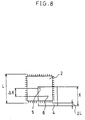
- Figure 8 shows an operation when the size of electronic part is varied.
- the divisional recognition can be performed even when the size of electronic part is varied.
Landscapes
- Engineering & Computer Science (AREA)
- Operations Research (AREA)
- Manufacturing & Machinery (AREA)
- Microelectronics & Electronic Packaging (AREA)
- Supply And Installment Of Electrical Components (AREA)
- Automatic Assembly (AREA)
Applications Claiming Priority (3)
| Application Number | Priority Date | Filing Date | Title |
|---|---|---|---|
| JP15872796A JP3647146B2 (ja) | 1996-06-20 | 1996-06-20 | 電子部品実装装置および電子部品実装方法 |
| JP158727/96 | 1996-06-20 | ||
| PCT/JP1997/002123 WO1997049273A1 (en) | 1996-06-20 | 1997-06-19 | Electronic part mounting apparatus |
Publications (2)
| Publication Number | Publication Date |
|---|---|
| EP0862355A1 true EP0862355A1 (de) | 1998-09-02 |
| EP0862355A4 EP0862355A4 (de) | 2000-10-18 |
Family
ID=15678023
Family Applications (1)
| Application Number | Title | Priority Date | Filing Date |
|---|---|---|---|
| EP97927400A Withdrawn EP0862355A4 (de) | 1996-06-20 | 1997-06-19 | Bestuckungseinrichtung fur elektronische teile |
Country Status (5)
| Country | Link |
|---|---|
| US (1) | US6366310B1 (de) |
| EP (1) | EP0862355A4 (de) |
| JP (1) | JP3647146B2 (de) |
| CN (1) | CN1109488C (de) |
| WO (1) | WO1997049273A1 (de) |
Cited By (1)
| Publication number | Priority date | Publication date | Assignee | Title |
|---|---|---|---|---|
| WO2001008461A1 (de) * | 1999-07-23 | 2001-02-01 | Pulsotronic Merten Gmbh & Co. Kg | Inspektionsvorrichtung für bauteile |
Families Citing this family (24)
| Publication number | Priority date | Publication date | Assignee | Title |
|---|---|---|---|---|
| JP2002374098A (ja) * | 2001-04-13 | 2002-12-26 | Yamaha Corp | 半導体パッケージ及び半導体パッケージの実装方法 |
| WO2004016064A1 (en) * | 2002-08-08 | 2004-02-19 | Matsushita Electric Industrial Co., Ltd. | Device and method for detecting whether or not component holder is good, and apparatus and method for mounting electronic component |
| JP4041768B2 (ja) * | 2002-09-12 | 2008-01-30 | 松下電器産業株式会社 | 部品装着ヘッド |
| US20040092048A1 (en) * | 2002-11-13 | 2004-05-13 | Chiu-Tien Hsu | Angle control system including a display device configured with two imaging windows that simultaneously display the same image captured by a single camera |
| KR101113838B1 (ko) * | 2004-11-30 | 2012-02-29 | 삼성테크윈 주식회사 | 전자부품 실장 방법 및 이를 채택한 부품 실장기 |
| JP4587877B2 (ja) * | 2005-06-02 | 2010-11-24 | Juki株式会社 | 部品実装装置 |
| JP4664752B2 (ja) * | 2005-06-30 | 2011-04-06 | Juki株式会社 | 部品吸着方法及び装置 |
| IL175455A0 (en) * | 2006-05-07 | 2007-08-19 | Penta I Ltd | A system and a method for imaging, automatic and at once, objects' six-faces |
| JP4903627B2 (ja) * | 2007-04-24 | 2012-03-28 | Juki株式会社 | 表面実装機、及び、そのカメラ位置補正方法 |
| JP4952476B2 (ja) * | 2007-09-25 | 2012-06-13 | パナソニック株式会社 | 電子部品実装システム |
| JP5153488B2 (ja) * | 2008-07-09 | 2013-02-27 | 富士機械製造株式会社 | 部品画像取り込み装置及び部品画像取り込み方法 |
| JP4829941B2 (ja) * | 2008-08-22 | 2011-12-07 | ヤマハ発動機株式会社 | 表面実装機 |
| JP4613998B2 (ja) * | 2008-12-15 | 2011-01-19 | パナソニック株式会社 | 部品実装装置及び部品実装方法 |
| JP4720901B2 (ja) * | 2008-12-15 | 2011-07-13 | パナソニック株式会社 | 部品実装方法 |
| DE102009016288B4 (de) * | 2009-01-02 | 2013-11-21 | Singulus Technologies Ag | Verfahren und Vorrichtung für die Ausrichtung von Substraten |
| EP2415021B1 (de) * | 2009-04-03 | 2016-07-27 | Singulus Technologies AG | Verfahren und vorrichtung für die ausrichtung von substraten |
| JP5444885B2 (ja) * | 2009-06-29 | 2014-03-19 | 富士通株式会社 | 実装装置及び実装方法 |
| JP2011155052A (ja) * | 2010-01-26 | 2011-08-11 | Hitachi High-Tech Instruments Co Ltd | 部品取出位置の教示方法及び電子部品装着装置 |
| CN106879245A (zh) * | 2012-02-08 | 2017-06-20 | Juki株式会社 | 电子部件安装装置、电子部件安装系统以及电子部件安装方法 |
| JP5918622B2 (ja) * | 2012-05-11 | 2016-05-18 | ヤマハ発動機株式会社 | 部品または基板の作業装置および部品実装装置 |
| US9778647B2 (en) * | 2012-12-28 | 2017-10-03 | Fuji Machine Mfg. Co., Ltd. | Working machine and positional deviation data acquisition method |
| JP2015223649A (ja) * | 2014-05-27 | 2015-12-14 | 株式会社安川電機 | ギヤ組み込みシステムおよびギヤ組み込み方法 |
| JP6741414B2 (ja) * | 2015-11-27 | 2020-08-19 | 川崎重工業株式会社 | 部品実装ロボットシステム |
| CN117322151A (zh) * | 2021-06-07 | 2023-12-29 | 株式会社富士 | 元件安装机以及电子元件的拍摄方法 |
Family Cites Families (13)
| Publication number | Priority date | Publication date | Assignee | Title |
|---|---|---|---|---|
| JPH0652169B2 (ja) * | 1986-01-31 | 1994-07-06 | 松下電器産業株式会社 | 部品位置認識方法及び装置 |
| JPH0773160B2 (ja) * | 1986-11-20 | 1995-08-02 | 松下電器産業株式会社 | 部品認識装置 |
| JPH01321700A (ja) * | 1988-06-23 | 1989-12-27 | Toshiba Corp | 位置合せ装置 |
| JPH0724360B2 (ja) * | 1990-02-20 | 1995-03-15 | 松下電工株式会社 | 部品の位置補正方法 |
| US5627913A (en) * | 1990-08-27 | 1997-05-06 | Sierra Research And Technology, Inc. | Placement system using a split imaging system coaxially coupled to a component pickup means |
| JP2965362B2 (ja) * | 1991-01-28 | 1999-10-18 | 松下電器産業株式会社 | 電子部品認識方法 |
| US5420691A (en) * | 1991-03-15 | 1995-05-30 | Matsushita Electric Industrial Co., Ltd. | Electric component observation system |
| JP3061903B2 (ja) * | 1991-08-27 | 2000-07-10 | 富士機械製造株式会社 | 保持位置検出機能を備えた電子部品保持・搬送装置 |
| US5237622A (en) * | 1991-12-04 | 1993-08-17 | Micron Technology, Inc. | Semiconductor pick-and-place machine automatic calibration apparatus |
| JPH07115296A (ja) * | 1993-10-15 | 1995-05-02 | Sanyo Electric Co Ltd | 部品実装機の制御装置 |
| JP3369695B2 (ja) * | 1994-01-19 | 2003-01-20 | パイオニア株式会社 | 電子部品位置合せ用カメラの調整装置 |
| CN1066907C (zh) * | 1994-03-30 | 2001-06-06 | 松下电器产业株式会社 | 电子元件装配装置 |
| JP3295529B2 (ja) * | 1994-05-06 | 2002-06-24 | 松下電器産業株式会社 | Ic部品実装方法及び装置 |
-
1996
- 1996-06-20 JP JP15872796A patent/JP3647146B2/ja not_active Expired - Fee Related
-
1997
- 1997-06-19 CN CN97190754A patent/CN1109488C/zh not_active Expired - Fee Related
- 1997-06-19 EP EP97927400A patent/EP0862355A4/de not_active Withdrawn
- 1997-06-19 WO PCT/JP1997/002123 patent/WO1997049273A1/ja not_active Ceased
- 1997-06-19 US US09/029,097 patent/US6366310B1/en not_active Expired - Fee Related
Non-Patent Citations (2)
| Title |
|---|
| No further relevant documents disclosed * |
| See also references of WO9749273A1 * |
Cited By (1)
| Publication number | Priority date | Publication date | Assignee | Title |
|---|---|---|---|---|
| WO2001008461A1 (de) * | 1999-07-23 | 2001-02-01 | Pulsotronic Merten Gmbh & Co. Kg | Inspektionsvorrichtung für bauteile |
Also Published As
| Publication number | Publication date |
|---|---|
| JP3647146B2 (ja) | 2005-05-11 |
| US6366310B1 (en) | 2002-04-02 |
| CN1109488C (zh) | 2003-05-21 |
| JPH1013097A (ja) | 1998-01-16 |
| WO1997049273A1 (en) | 1997-12-24 |
| EP0862355A4 (de) | 2000-10-18 |
| CN1196873A (zh) | 1998-10-21 |
Similar Documents
| Publication | Publication Date | Title |
|---|---|---|
| EP0862355A1 (de) | Bestuckungseinrichtung fur elektronische teile | |
| US5249356A (en) | Method and apparatus for mounting electronic component | |
| US5172468A (en) | Mounting apparatus for electronic parts | |
| KR20000070860A (ko) | 위치 설정 시스템 | |
| JP3523972B2 (ja) | 部品実装方法及び部品実装装置 | |
| JPH0871780A (ja) | レーザ位置決め加工方法及び装置 | |
| JP4298473B2 (ja) | 表面実装機 | |
| JP2707548B2 (ja) | 視覚認識装置の座標補正方法 | |
| JP2811856B2 (ja) | 電子部品の実装装置及び実装方法 | |
| JP3161470B2 (ja) | 部品認識装置、部品実装機およびデータ作成機 | |
| JP2872765B2 (ja) | チップ部品の装着装置 | |
| KR980007929A (ko) | 칩 마운터용 고정도 화상 입력 장치 | |
| JP3773989B2 (ja) | 部品実装方法および装置 | |
| JPH06314897A (ja) | チップマウンター | |
| JPS60134671A (ja) | ビデオカメラ | |
| JPH0964597A (ja) | 部品実装装置 | |
| JP4332714B2 (ja) | 電子部品実装装置 | |
| JP3006106B2 (ja) | 部品実装装置 | |
| JPH0883999A (ja) | 電子部品実装装置 | |
| JPH09282464A (ja) | 画像認識装置及び方法 | |
| JP3713097B2 (ja) | 部品実装装置 | |
| KR0135466B1 (ko) | 전자부품 실장기의 부품 인식방법 | |
| KR0183654B1 (ko) | 스크린 프린터의 인쇄 위치 보정장치 | |
| JPH1197898A (ja) | 部品撮像装置 | |
| JPH098497A (ja) | 部品実装機の高速位置決め方法 |
Legal Events
| Date | Code | Title | Description |
|---|---|---|---|
| PUAI | Public reference made under article 153(3) epc to a published international application that has entered the european phase |
Free format text: ORIGINAL CODE: 0009012 |
|
| 17P | Request for examination filed |
Effective date: 19980605 |
|
| AK | Designated contracting states |
Kind code of ref document: A1 Designated state(s): DE GB |
|
| RAP1 | Party data changed (applicant data changed or rights of an application transferred) |
Owner name: MATSUSHITA ELECTRIC INDUSTRIAL CO., LTD. |
|
| A4 | Supplementary search report drawn up and despatched |
Effective date: 20000901 |
|
| AK | Designated contracting states |
Kind code of ref document: A4 Designated state(s): DE GB |
|
| 17Q | First examination report despatched |
Effective date: 20040115 |
|
| 17Q | First examination report despatched |
Effective date: 20040115 |
|
| GRAP | Despatch of communication of intention to grant a patent |
Free format text: ORIGINAL CODE: EPIDOSNIGR1 |
|
| RAP1 | Party data changed (applicant data changed or rights of an application transferred) |
Owner name: PANASONIC CORPORATION |
|
| STAA | Information on the status of an ep patent application or granted ep patent |
Free format text: STATUS: THE APPLICATION IS DEEMED TO BE WITHDRAWN |
|
| 18D | Application deemed to be withdrawn |
Effective date: 20081108 |