EP0862955A2 - Alignement automatique de cannelures de cylindres - Google Patents
Alignement automatique de cannelures de cylindres Download PDFInfo
- Publication number
- EP0862955A2 EP0862955A2 EP98301470A EP98301470A EP0862955A2 EP 0862955 A2 EP0862955 A2 EP 0862955A2 EP 98301470 A EP98301470 A EP 98301470A EP 98301470 A EP98301470 A EP 98301470A EP 0862955 A2 EP0862955 A2 EP 0862955A2
- Authority
- EP
- European Patent Office
- Prior art keywords
- roll
- roll stand
- work rolls
- work
- reference location
- Prior art date
- Legal status (The legal status is an assumption and is not a legal conclusion. Google has not performed a legal analysis and makes no representation as to the accuracy of the status listed.)
- Granted
Links
Images


Classifications
-
- B—PERFORMING OPERATIONS; TRANSPORTING
- B21—MECHANICAL METAL-WORKING WITHOUT ESSENTIALLY REMOVING MATERIAL; PUNCHING METAL
- B21B—ROLLING OF METAL
- B21B37/00—Control devices or methods specially adapted for metal-rolling mills or the work produced thereby
-
- B—PERFORMING OPERATIONS; TRANSPORTING
- B21—MECHANICAL METAL-WORKING WITHOUT ESSENTIALLY REMOVING MATERIAL; PUNCHING METAL
- B21B—ROLLING OF METAL
- B21B31/00—Rolling stand structures; Mounting, adjusting, or interchanging rolls, roll mountings, or stand frames
- B21B31/16—Adjusting or positioning rolls
Definitions
- This invention relates to rolling mills in which bars, rods and other like long products are continuously hot rolled in the roll passes of multi-groove rolls, and is concerned in particular with an improvement in the alignment of the grooves of individual roll passes with each other, as well as the alignment of roll passes with the mill passline (for vertical stands) and with the mill center line for (horizontal stands).
- the object of the present invention is to provide a method and system for automatically achieving precise, rapid and repeatable groove settings and roll pass alignments.
- data representing the axial distance of the center of each groove of a work roll from a first reference location on the work roll is determined and stored in the memory of a data processing system.
- the work rolls are then mounted in the roll stand and the grooves of a selected "setup" roll pass are brought into alignment with each other.
- the roll stand is placed on the rolling line, the setup pass is aligned with the mill passline in the case of vertical stands, or with the mill center line in the case of horizontal roll stands, and data representing the relative positions of the work rolls to the roll stand and of the roll stand to another reference location is obtained and stored in the memory of the data processing system.
- This data is then employed by the system to calculate and automatically effect adjustments to the roll stand and work rolls in order to precisely align other roll passes with the mill passline or center line. Time consuming manual adjustments and repetitive trial runs are avoided, with concomitant reductions in mill down time.
- a typical work roll is shown at 10 comprising a roll barrel 12 with reduced diameter necks 14 extending axially in opposite directions from roll end faces 16.
- the roll barrel is grooved as indicated typically at 18 and carries identifying indicia 20.
- An initial step in the method of the present invention entails determining the axial distance "X" of the center of each groove 18 from a reference location on the roll.
- the reference location can be a roll end face 16 as shown in Figure 1, or another arbitrarily selected location evidenced by some permanent mark on the roll surface.
- this information can either be measured or obtained from the roll manufacturer.
- roll profiles undergo changes as a result of redressing the same information can be obtained from computer generated data or physical measurements performed by mill personnel.
- “First data" including for each work roll 10, the spacings X of the roll grooves and the roll identifying indicia 20, is loaded into the memory 24 of a data processing system schematically depicted in Figure 4.
- the indicia 20 is typically entered manually via a keyboard 22 or other comparable input device.
- the groove spacings X can also be entered manually, or if represented by computer generated data, can be entered automatically when being compiled by operating personnel.
- Memory 24 is operatively coupled to a computer processor 26.
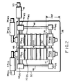
- two work rolls 10 DS ,10 WS are assembled with their respective bearing chocks 28 DS ,28 WS ;30 DS ,30 WS and mounted in a conventional vertical roll stand 32.
- the chocks 28, 30 may be of any known type which permit axial adjustment of the work rolls with respect to the roll stand.
- the upper chocks 28 may contain mechanisms to effect the axial roll adjustments, and the lower chocks 30 may be configured and mounted to accommodate such adjustments.
- the axial roll adjustment mechanisms are centered, i.e., moved to half their fill ranges, before the work rolls and their respective chock sets are loaded into the stand housing.
- the axial adjustment mechanisms of the upper chocks 28 DS ,28 WS are driven by separately powered actuators 34 DS ,34 WS
- Position measuring devices 36 DS ,36 WS are coupled respectively to the actuators 34 DS , 34 WS .
- the actuators 34 DS , 34 WS are controlled by signals received from the computer processor 26, with the position measuring devices 36 DS , 36 WS generating feed back signals representative of the axial adjustments being made to the work rolls.
- the position measuring devices 36 DS , 36 WS are reset to a known value.
- a prerecorded constant representing the axial distance Z RFHB between the first reference location 16 on each work roll and a second reference location 38 on the roll stand is stored as "second data" in memory 24.
- the second reference location 38 may be the underside of the roll stand housing, as illustrated, or at any other convenient location capable of providing a reliable reference datum.
- chock actuators 34 DS ,34 WS are then manually operated to effect the axial roll adjustments necessary to bring the roll grooves of a setup pass 40 into precise alignment with each other.
- the accuracy of groove alignment can be checked optically using known methods and equipment.
- Gap separation between the grooves of each roll pass is controlled by roll parting adjustment mechanisms 42 DS ,44 DS ;42 WS ,44 WS . These adjustment mechanisms are operably coupled, for example by shafts 46 and are driven by a common drive 48 to effect simultaneous symmetrical roll parting adjustments.
- a position measuring device 50 is associated with drive 48. Again, as shown in Figure 4, the drive 48 is controlled by signals received from the computer processor 26, with the position measuring device 50 generating feedback signals representative of roll gap adjustments.
- the drive 48 is operated to close the rolls to a known gap, which may be defined by a shim 52, after which the position measuring device 50 is also reset to a known value and the shim then removed.
- the roll stand 32 is then moved to the rolling line and mounted on an elevator platform 54.
- the following dimensions are relevant to a continued description of the invention:
- the elevator platform is vertically adjustable by powered mechanisms 56 of known design, operably coupled as by a shaft 58 or the like and driven by an actuator 60.
- Another position measuring device 62 is coupled to the actuator 60.
- the support surface of the elevator platform defines a third reference location 64 spaced beneath the mill passline by the distance Y PL .
- the elevator actuator 60 operates in response to control signals received from the computer processor 26, and the position measuring device 62 provides feedback signals to the computer processor representative of the elevation Y ELV .
- the computer processor 26 will retrieve from memory 24 the distances X DS and X WS of the setup pass grooves.
- This movement will place the setup pass 40 in approximate alignment with the mill passline.
- the elevator platform 54 and/or the work rolls 10 DS , 10 WS may be adjusted further through the computer processor. Any further roll adjustments will be performed simultaneously i.e., in tandem, so as not to alter the precise alignment of the grooves of the setup pass 40 with respect to each other.
- the accuracy of the setup pass with the mill passline can be optically checked and verified by known procedures using conventional equipment.
- the third data includes the sum of axial roll adjustments dx DS ,dx WS made to align the grooves of the setup pass 40 with each other, as well as any further tandem axial adjustments made to the work rolls to achieve more precise alignment of the setup pass with the mill passline.
- the fourth data includes the sum of the elevator displacement Y ELV made to align the setup pass 40 approximately with the mill passline, and any further fine tuning adjustments made to the elevator to achieve more precise setup pass alignment.
- Rolling can then commence through setup pass 40. If another roll pass is required for rolling, this can be brought into alignment with the mill passline through automatic adjustment, controlled by the computer processor 26, of the elevator platform actuator 60 and axial roll actuators 34 DS ,34 WS .
- the computer processor 26 will retrieve from memory 24, using the identification indicia 20 for the work rolls 10 DS and 10 WS and the number of the next pass "NP" entered by the operator, the distances X NPDS and X NPWS from roll end face 16, shown in Figure 2, to the drive side and work side grooves of pass NP.
- the computer processor 26 is programmed to employ the first, second, third and fourth data as follows:
- Y NP Y SU + (X WSSU + dx WSSU + X DSSU + dX DSSU X NPDS - X NPWS )/2
- the computer processor 26 controls elevator actuator 60 to position the elevator platform at Y NP , using feedback from position measuring device 62.
- dX DS Y SU - Y MEAS + dX DSSU + X DSSU - X NPDS
- dx WS Y SU - Y MEAS + dX WSSU - X NPWS
- the computer processor 26 operates the work roll actuators 34 DS and 34 WS to move the drive side and work side rolls 10 DS , 10 WS within their respective bearing by distances dxDs and dxws using feedback from position measuring devices 36 DS and 36 WS .
Landscapes
- Engineering & Computer Science (AREA)
- Mechanical Engineering (AREA)
- Control Of Metal Rolling (AREA)
- Length Measuring Devices With Unspecified Measuring Means (AREA)
- Reduction Rolling/Reduction Stand/Operation Of Reduction Machine (AREA)
- Spinning Or Twisting Of Yarns (AREA)
- Treatment Of Fiber Materials (AREA)
- Metal Rolling (AREA)
- Absorbent Articles And Supports Therefor (AREA)
- Finish Polishing, Edge Sharpening, And Grinding By Specific Grinding Devices (AREA)
- Jigs For Machine Tools (AREA)
- Preliminary Treatment Of Fibers (AREA)
- Automatic Assembly (AREA)
- Replacement Of Web Rolls (AREA)
- Undergarments, Swaddling Clothes, Handkerchiefs Or Underwear Materials (AREA)
Applications Claiming Priority (2)
| Application Number | Priority Date | Filing Date | Title |
|---|---|---|---|
| US08/813,599 US5949684A (en) | 1997-03-07 | 1997-03-07 | Automatic roll groove alignment |
| US813599 | 1997-03-07 |
Publications (3)
| Publication Number | Publication Date |
|---|---|
| EP0862955A2 true EP0862955A2 (fr) | 1998-09-09 |
| EP0862955A3 EP0862955A3 (fr) | 1999-01-20 |
| EP0862955B1 EP0862955B1 (fr) | 2003-02-05 |
Family
ID=25212866
Family Applications (1)
| Application Number | Title | Priority Date | Filing Date |
|---|---|---|---|
| EP98301470A Expired - Lifetime EP0862955B1 (fr) | 1997-03-07 | 1998-02-27 | Alignement automatique de cannelures de cylindres |
Country Status (12)
| Country | Link |
|---|---|
| US (1) | US5949684A (fr) |
| EP (1) | EP0862955B1 (fr) |
| JP (1) | JP2949429B2 (fr) |
| KR (1) | KR100252598B1 (fr) |
| CN (1) | CN1093439C (fr) |
| AT (1) | ATE232146T1 (fr) |
| AU (1) | AU701079B2 (fr) |
| BR (1) | BR9800823A (fr) |
| CA (1) | CA2229304C (fr) |
| DE (1) | DE69811130T2 (fr) |
| ES (1) | ES2191905T3 (fr) |
| PL (1) | PL185579B1 (fr) |
Families Citing this family (13)
| Publication number | Priority date | Publication date | Assignee | Title |
|---|---|---|---|---|
| US6350369B1 (en) * | 1998-04-14 | 2002-02-26 | California Institute Of Technology | Method and system for determining analyte activity |
| ES2234703T3 (es) * | 1999-10-17 | 2005-07-01 | KARL FUHR GMBH & CO. KG | Dispositivo de direccionamiento para un mecanismo de laminado. |
| KR100361851B1 (ko) * | 2001-12-26 | 2002-11-22 | 유병섭 | 이형 선재용 압연기의 롤러 어셈블리 |
| US7171759B1 (en) | 2003-06-02 | 2007-02-06 | Mark Vincent Loen | Method and apparatus to accurately measure the angular orientation of two surfaces |
| US20070127011A1 (en) * | 2003-09-08 | 2007-06-07 | Loen Mark V | Method and Apparatus for Measuring the Angular Orientation Between Two Surfaces |
| US7312861B2 (en) * | 2003-09-08 | 2007-12-25 | Mark Vincent Loen | Method and apparatus for measuring the angular orientation between two surfaces |
| US20050125993A1 (en) * | 2003-11-07 | 2005-06-16 | Madsen David D. | Pick and place machine with improved setup and operation procedure |
| KR100711384B1 (ko) * | 2005-12-19 | 2007-04-30 | 주식회사 포스코 | 선재 압연롤의 공형부 센터와 롤갭 조정장치 및 조정방법 |
| IT1402352B1 (it) * | 2010-09-15 | 2013-08-30 | Sms Meer Spa | Apparato per la laminazione ad alta produttivita', in particolare per la laminazione di profilati o barre |
| CN102319739B (zh) * | 2011-10-19 | 2013-05-08 | 北京金自天正智能控制股份有限公司 | 二辊斜轧穿孔机辗轧角调整装置 |
| DE102020202107B4 (de) * | 2020-02-19 | 2022-08-11 | Kocks Technik Gmbh & Co Kg | Vorrichtung zum Belasten von Walzen und Innenteilen eines Walzgerüsts während der Justierung einzelner Walzenkaliber |
| CN113333473B (zh) * | 2021-06-04 | 2023-06-27 | 广东韶钢松山股份有限公司 | 一种调整立辊错槽的装置及其使用方法 |
| CN115283442A (zh) * | 2022-08-12 | 2022-11-04 | 天津中鹏科技发展有限公司 | 一种可升降调节辊系的立辊轧机 |
Family Cites Families (4)
| Publication number | Priority date | Publication date | Assignee | Title |
|---|---|---|---|---|
| US3429167A (en) * | 1966-04-12 | 1969-02-25 | Morgan Construction Co | Axial roll adjusting mechanism |
| US4154074A (en) * | 1978-02-27 | 1979-05-15 | Morgan Construction Company | Roll stand for a rod or bar rolling mill |
| GB8905608D0 (en) * | 1989-03-11 | 1989-04-26 | Atkinson Craig | Mill roll adjustment |
| JPH03106506A (ja) * | 1989-09-19 | 1991-05-07 | Nkk Corp | 圧延機のロールカリバー中心とパスライン中心を一致させる調整方法 |
-
1997
- 1997-03-07 US US08/813,599 patent/US5949684A/en not_active Expired - Fee Related
-
1998
- 1998-02-12 CA CA002229304A patent/CA2229304C/fr not_active Expired - Fee Related
- 1998-02-27 EP EP98301470A patent/EP0862955B1/fr not_active Expired - Lifetime
- 1998-02-27 CN CN98105295A patent/CN1093439C/zh not_active Expired - Fee Related
- 1998-02-27 AT AT98301470T patent/ATE232146T1/de not_active IP Right Cessation
- 1998-02-27 ES ES98301470T patent/ES2191905T3/es not_active Expired - Lifetime
- 1998-02-27 DE DE69811130T patent/DE69811130T2/de not_active Expired - Fee Related
- 1998-03-04 PL PL98325143A patent/PL185579B1/pl not_active IP Right Cessation
- 1998-03-04 BR BR9800823-4A patent/BR9800823A/pt not_active IP Right Cessation
- 1998-03-05 JP JP10053346A patent/JP2949429B2/ja not_active Expired - Fee Related
- 1998-03-05 AU AU57376/98A patent/AU701079B2/en not_active Ceased
- 1998-03-06 KR KR1019980007452A patent/KR100252598B1/ko not_active Expired - Fee Related
Also Published As
| Publication number | Publication date |
|---|---|
| KR19980079981A (ko) | 1998-11-25 |
| ATE232146T1 (de) | 2003-02-15 |
| KR100252598B1 (ko) | 2000-04-15 |
| DE69811130T2 (de) | 2003-11-20 |
| DE69811130D1 (de) | 2003-03-13 |
| CA2229304A1 (fr) | 1998-09-07 |
| AU701079B2 (en) | 1999-01-21 |
| CA2229304C (fr) | 2001-06-05 |
| BR9800823A (pt) | 1999-09-14 |
| JP2949429B2 (ja) | 1999-09-13 |
| EP0862955A3 (fr) | 1999-01-20 |
| PL325143A1 (en) | 1998-09-14 |
| CN1093439C (zh) | 2002-10-30 |
| CN1201724A (zh) | 1998-12-16 |
| AU5737698A (en) | 1998-09-10 |
| JPH10249420A (ja) | 1998-09-22 |
| EP0862955B1 (fr) | 2003-02-05 |
| ES2191905T3 (es) | 2003-09-16 |
| PL185579B1 (pl) | 2003-06-30 |
| US5949684A (en) | 1999-09-07 |
Similar Documents
| Publication | Publication Date | Title |
|---|---|---|
| EP0862955B1 (fr) | Alignement automatique de cannelures de cylindres | |
| US4761979A (en) | Roller bending apparatus equipped with a curvature measuring unit | |
| DE602004010293T2 (de) | Verfahren zur erhöhung der steuergenauigkeit des weges eines produkts in einer richtmaschine mit ineinandergreifenden walzen und zur durchführung desselben verwendete richtanlage | |
| RU2018386C1 (ru) | Способ установки валков универсальной прокатной клети | |
| US4934166A (en) | Rolling mill with axially shiftable rolls and process for adjusting the profile of such rolls | |
| CN101052480B (zh) | 用于对准辊轧机架中进料装置和轧道的设备和方法 | |
| EP0388096B1 (fr) | Ajustage des cylindres pour un laminoir | |
| US5806360A (en) | Rolling mill installation | |
| US5195347A (en) | Guide device for shape rolling | |
| US5253039A (en) | Process and apparatus for measuring sizes of steel sections | |
| DE1285431B (de) | Induktions-Messlehre zum Einstellen und laufenden Messen des Walzspaltes in automatisch geregelten Walzgeruesten | |
| MXPA98001837A (en) | Automat roller slot alignment | |
| JP7429302B2 (ja) | 垂直圧延スタンドの垂直ローラを自動的に較正する方法及び方法を実施する較正装置 | |
| US6134935A (en) | Apparatus and method for determining and setting a stand center and adjusting positions of a roll stand | |
| US6065318A (en) | Housingless rolling mill | |
| KR20010062790A (ko) | 만능 롤 스탠드용 보정 방법 | |
| US4290289A (en) | Spacial alignment method for rolling mill rolls and chocks | |
| JP7209013B2 (ja) | 油圧式のロール調整装置を備えた傾斜圧延機 | |
| US20210078059A1 (en) | Rolling mill, and method for setting rolling mill | |
| US11400499B2 (en) | Method for setting rolling mill, and rolling mill | |
| JPS635813A (ja) | ロ−ル調整方法 | |
| US4312209A (en) | Method for operating a strip rolling mill | |
| RU2799466C2 (ru) | Способ и устройство для выравнивания проволоки или ленты | |
| US2365944A (en) | Method for aligning roll passes | |
| KR20240152665A (ko) | 레이저를 이용한 압연롤 정렬 측정 장치 및 방법 |
Legal Events
| Date | Code | Title | Description |
|---|---|---|---|
| PUAI | Public reference made under article 153(3) epc to a published international application that has entered the european phase |
Free format text: ORIGINAL CODE: 0009012 |
|
| AK | Designated contracting states |
Kind code of ref document: A2 Designated state(s): AT DE ES FR GB IT SE |
|
| AX | Request for extension of the european patent |
Free format text: AL;LT;LV;MK;RO;SI |
|
| PUAL | Search report despatched |
Free format text: ORIGINAL CODE: 0009013 |
|
| AK | Designated contracting states |
Kind code of ref document: A3 Designated state(s): AT BE CH DE DK ES FI FR GB GR IE IT LI LU MC NL PT SE |
|
| AX | Request for extension of the european patent |
Free format text: AL;LT;LV;MK;RO;SI |
|
| 17P | Request for examination filed |
Effective date: 19990308 |
|
| AKX | Designation fees paid |
Free format text: AT DE ES FR GB IT SE |
|
| GRAG | Despatch of communication of intention to grant |
Free format text: ORIGINAL CODE: EPIDOS AGRA |
|
| 17Q | First examination report despatched |
Effective date: 20020304 |
|
| GRAG | Despatch of communication of intention to grant |
Free format text: ORIGINAL CODE: EPIDOS AGRA |
|
| GRAH | Despatch of communication of intention to grant a patent |
Free format text: ORIGINAL CODE: EPIDOS IGRA |
|
| GRAH | Despatch of communication of intention to grant a patent |
Free format text: ORIGINAL CODE: EPIDOS IGRA |
|
| GRAA | (expected) grant |
Free format text: ORIGINAL CODE: 0009210 |
|
| AK | Designated contracting states |
Designated state(s): AT DE ES FR GB IT SE |
|
| REG | Reference to a national code |
Ref country code: GB Ref legal event code: FG4D |
|
| PG25 | Lapsed in a contracting state [announced via postgrant information from national office to epo] |
Ref country code: AT Free format text: LAPSE BECAUSE OF NON-PAYMENT OF DUE FEES Effective date: 20030227 |
|
| PG25 | Lapsed in a contracting state [announced via postgrant information from national office to epo] |
Ref country code: SE Free format text: LAPSE BECAUSE OF NON-PAYMENT OF DUE FEES Effective date: 20030228 Ref country code: ES Free format text: LAPSE BECAUSE OF NON-PAYMENT OF DUE FEES Effective date: 20030228 |
|
| PGFP | Annual fee paid to national office [announced via postgrant information from national office to epo] |
Ref country code: FR Payment date: 20030228 Year of fee payment: 6 |
|
| REF | Corresponds to: |
Ref document number: 69811130 Country of ref document: DE Date of ref document: 20030313 Kind code of ref document: P |
|
| REG | Reference to a national code |
Ref country code: SE Ref legal event code: TRGR |
|
| PG25 | Lapsed in a contracting state [announced via postgrant information from national office to epo] |
Ref country code: GB Free format text: LAPSE BECAUSE OF NON-PAYMENT OF DUE FEES Effective date: 20030505 |
|
| PGFP | Annual fee paid to national office [announced via postgrant information from national office to epo] |
Ref country code: DE Payment date: 20030724 Year of fee payment: 6 |
|
| ET | Fr: translation filed | ||
| REG | Reference to a national code |
Ref country code: ES Ref legal event code: FG2A Ref document number: 2191905 Country of ref document: ES Kind code of ref document: T3 |
|
| EUG | Se: european patent has lapsed | ||
| PLBE | No opposition filed within time limit |
Free format text: ORIGINAL CODE: 0009261 |
|
| STAA | Information on the status of an ep patent application or granted ep patent |
Free format text: STATUS: NO OPPOSITION FILED WITHIN TIME LIMIT |
|
| GBPC | Gb: european patent ceased through non-payment of renewal fee |
Effective date: 20030505 |
|
| 26N | No opposition filed |
Effective date: 20031106 |
|
| REG | Reference to a national code |
Ref country code: ES Ref legal event code: FD2A Effective date: 20030228 |
|
| PG25 | Lapsed in a contracting state [announced via postgrant information from national office to epo] |
Ref country code: DE Free format text: LAPSE BECAUSE OF NON-PAYMENT OF DUE FEES Effective date: 20040901 |
|
| PG25 | Lapsed in a contracting state [announced via postgrant information from national office to epo] |
Ref country code: FR Free format text: LAPSE BECAUSE OF NON-PAYMENT OF DUE FEES Effective date: 20041029 |
|
| REG | Reference to a national code |
Ref country code: FR Ref legal event code: ST |
|
| PG25 | Lapsed in a contracting state [announced via postgrant information from national office to epo] |
Ref country code: IT Free format text: LAPSE BECAUSE OF NON-PAYMENT OF DUE FEES Effective date: 20050227 |