EP0863620A2 - Diversity-Schaltung - Google Patents
Diversity-Schaltung Download PDFInfo
- Publication number
- EP0863620A2 EP0863620A2 EP98103017A EP98103017A EP0863620A2 EP 0863620 A2 EP0863620 A2 EP 0863620A2 EP 98103017 A EP98103017 A EP 98103017A EP 98103017 A EP98103017 A EP 98103017A EP 0863620 A2 EP0863620 A2 EP 0863620A2
- Authority
- EP
- European Patent Office
- Prior art keywords
- signal
- diversity
- antenna
- circuit
- received
- Prior art date
- Legal status (The legal status is an assumption and is not a legal conclusion. Google has not performed a legal analysis and makes no representation as to the accuracy of the status listed.)
- Granted
Links
Images



Classifications
-
- H—ELECTRICITY
- H04—ELECTRIC COMMUNICATION TECHNIQUE
- H04B—TRANSMISSION
- H04B7/00—Radio transmission systems, i.e. using radiation field
- H04B7/02—Diversity systems; Multi-antenna system, i.e. transmission or reception using multiple antennas
- H04B7/04—Diversity systems; Multi-antenna system, i.e. transmission or reception using multiple antennas using two or more spaced independent antennas
- H04B7/08—Diversity systems; Multi-antenna system, i.e. transmission or reception using multiple antennas using two or more spaced independent antennas at the receiving station
- H04B7/0891—Space-time diversity
- H04B7/0894—Space-time diversity using different delays between antennas
-
- Y—GENERAL TAGGING OF NEW TECHNOLOGICAL DEVELOPMENTS; GENERAL TAGGING OF CROSS-SECTIONAL TECHNOLOGIES SPANNING OVER SEVERAL SECTIONS OF THE IPC; TECHNICAL SUBJECTS COVERED BY FORMER USPC CROSS-REFERENCE ART COLLECTIONS [XRACs] AND DIGESTS
- Y02—TECHNOLOGIES OR APPLICATIONS FOR MITIGATION OR ADAPTATION AGAINST CLIMATE CHANGE
- Y02D—CLIMATE CHANGE MITIGATION TECHNOLOGIES IN INFORMATION AND COMMUNICATION TECHNOLOGIES [ICT], I.E. INFORMATION AND COMMUNICATION TECHNOLOGIES AIMING AT THE REDUCTION OF THEIR OWN ENERGY USE
- Y02D30/00—Reducing energy consumption in communication networks
- Y02D30/70—Reducing energy consumption in communication networks in wireless communication networks
Definitions
- the present invention relates to a diversity circuit, more specifically to a diversity circuit for antenna diversity of a radio communication system employing a spread spectrum system, such as code division multiple access (CDMA).
- CDMA code division multiple access
- a set of an antenna, receiver, and demodulator is needed for each of the diversity paths. Signals from each diversity path are combined at a final stage of signal processing by using the maximal ratio combining technique, where finally the signals from each diversity path are combined into one composite signal.
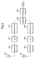
- Fig. 2 illustrates an example of the foregoing conventional circuit.
- Fig. 2 is a typical example of an antenna combining diversity circuit. Signals received by each of two antennas 201, 202 are respectively demodulated into base band signals by receivers 203, 204. The demodulated outputs of receivers 203, 204 are respectively converted into digital signals by A/D converters 205, 206. The digitally converted signals are respectively demodulated by digital demodulators 207, 208, where finally the two demodulated signals are added, or combined by a combiner 209. The output from the combiner 209 is decoded by a decoder 210 to reproduce transmitted data.
- a diversity circuit for receiving a spread spectrum modulated wave signal includes a plurality of antennas, a plurality of delay circuits that each give different delay times to a plurality of radiofrequency signals received by a plurality of the antennas, combining means for adding outputs of a plurality of the delay circuits, demodulation means for demodulating an output from the combining means, A/D conversion means for converting a demodulated result by the demodulation means into a digital signal, and digital signal processing means for processing an output from the A/D conversion means to decode.
- the signals received by a plurality of the antennas may be amplified by a plurality of amplifiers, and thereafter passed through the delay circuits, or, further converted into signals of intermediate frequencies by frequency conversion means, passed through the delay circuits, and thereafter combined and demodulated.
- the diversity circuit may be formed such that a radio-frequency wave signal received by one antenna is not processed as it is and only the signal received by the other one antenna is delayed by the delay circuit, and thereafter the two signals are combined.
- the digital signal processing means may apply a Rake reception system that gives de-spreading codes to each of signals having different delay times and combines the results, and a combined result may be decoded by decode means.
- differences in the delay times of the delay circuits are sufficiently larger than differences in transmission times by multipaths produced on separate transmission paths.
- the signals shifted in time base can be identified as signals passed through different communication lines, and can be separated as such.
- the present invention exploits the foregoing theory.
- one of the signals received by two antennas is shifted in time base with respect to the other one by a delay circuit, and both the time-shifted signal and the non-time-shifted signal are added or combined by a combiner at an earlier stage in the receiver.
- both signals pass through a shared demodulator and A/D converter, and then enter a Rake receiver to demodulate the signals.
- the invention can reduce the number of demodulators and A/D converters in the diversity system from two to one, and thereby reduce the scale of circuit.
- Fig. 1 is a block diagram of a first embodiment of the present invention.
- Radio-frequency signals received by antennas 101, 102 are amplified by amplifiers 103, 104. Of the two signals, only the radio-frequency signal received by the antenna 102 is delayed by a delay time T through a delay circuit 105 (hereafter, this route is called "path B").
- Delay circuit 105 may be implemented as an additional line length to achieve an appropriate delay, for example.
- the output from the delay circuit 105 and the output from the amplifier 103 (hereafter, this route is called "path A") is combined at a combiner 106.
- a shared receiver 107 lowers the frequency of the combined signal to that of a base band signal, which is converted into a digital signal by a shared A/D converter 108.
- a Rake receiver 109 demodulates the digital signal, and a decoder 110 decodes the demodulated result to reproduce transmitted data. Rake receivers are described in detail in Section 4.4 of "CDMA - Principles of Spread Spectrum Communication", by Andrew J. Viterbi, published June, 1995, which is incorporated herein by reference.
- the Rake receiver 109 takes on a configuration, for example, as shown in Fig. 4.
- a search correlator 408 gradually shifts the phase of a de-spreading code generated by de-spreading code generator 407 to calculate a correlation between the input signal and the de-spreading code.
- a delay profile (a graph showing the correlative value against the delay time in relation to de-spreading code) is acquired as shown in Fig. 3.
- the group A in Fig. 3 represents signals received through the path A, and the group B represents signals received through the path B.
- the peaks 2, 3 of the group A are delay components produced by multipaths on the transmission line of the peak 1
- the peaks 5, 6 of the group B are delay components produced by multipaths on the transmission line of the peak 4.
- the group B is delayed by a time T to the group A by the delay circuit 105. If the value of T is sufficiently large, such that the group A and the group B are not overlapped, the peaks of the groups can be separated as individual components that have the delay times of t1, t2, ..., t6.
- the search correlator 408 sets the values of t1, t2, ..., t6 to delay circuits 401, ... 406 as delays of the de-spreading codes inputted to finger receivers 411, ..., 416.
- the finger receivers 411, ..., 416 respectively calculate the correlative values of the peak levels at the delay time t1, t2, ..., t6, which are contained in each of the input signals.
- a combiner 409 applies a weighting to the calculated correlative values to thereby perform the Maximal Ratio Combining.
- the signals of the two paths A and B are maximum-peak-ratio-combined equivalently to the conventional combining diversity circuit having two separate diversity paths, and thereafter decoded by the decoder 110.
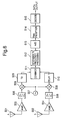
- Fig. 5 illustrates a second embodiment different from the first embodiment shown in Fig. 1, which, however, differs only in that a delay circuit 510 is located after a mixer 508, and is theoretically the same as Fig. 1.
- a mixer (or frequency converter) 508, 509 and a filter 505, 506 are provide in each path, and a tunable local oscillator 507 is provided as an input to the mixers 508, 509.
- IF processing element 512 provides filtering, amplifying and automatic gain control (AGC).
- the delay circuit 510 can be composed more easily using a SAW device, etc., which is advantageous. Thus, a smaller-sized delay circuit than one used in the first embodiment may be realized.
- Fig. 6 illustrates a third embodiment of the present invention.
- the third embodiment is similar to the second embodiment, but differs in that delay circuits, shown as SAW filters 510, 520, are provided in each path.
- the difference in delays between the SAW filters 510, 520 is such that a delay profile similar to that shown in Fig. 3 is realized. That is, SAW filter 510 is provided with a different delay than SAW filter 520.
- the present invention will reduce the scale of a combining diversity circuit employing a plurality of antennas, and be able to reduce the size, power consumption, and cost of the unit.
Landscapes
- Engineering & Computer Science (AREA)
- Computer Networks & Wireless Communication (AREA)
- Signal Processing (AREA)
- Radio Transmission System (AREA)
Applications Claiming Priority (3)
| Application Number | Priority Date | Filing Date | Title |
|---|---|---|---|
| JP9048685A JPH10247869A (ja) | 1997-03-04 | 1997-03-04 | ダイバーシティ回路 |
| JP4868597 | 1997-03-04 | ||
| JP48685/97 | 1997-03-04 |
Publications (3)
| Publication Number | Publication Date |
|---|---|
| EP0863620A2 true EP0863620A2 (de) | 1998-09-09 |
| EP0863620A3 EP0863620A3 (de) | 1998-12-30 |
| EP0863620B1 EP0863620B1 (de) | 2003-05-07 |
Family
ID=12810181
Family Applications (1)
| Application Number | Title | Priority Date | Filing Date |
|---|---|---|---|
| EP98103017A Expired - Lifetime EP0863620B1 (de) | 1997-03-04 | 1998-02-20 | Diversity-Schaltung |
Country Status (7)
| Country | Link |
|---|---|
| US (1) | US6229840B1 (de) |
| EP (1) | EP0863620B1 (de) |
| JP (1) | JPH10247869A (de) |
| KR (1) | KR100291980B1 (de) |
| AU (1) | AU737560B2 (de) |
| CA (1) | CA2230932A1 (de) |
| DE (1) | DE69814221T2 (de) |
Cited By (10)
| Publication number | Priority date | Publication date | Assignee | Title |
|---|---|---|---|---|
| WO1999017466A1 (en) * | 1997-09-29 | 1999-04-08 | Qualcomm Incorporated | Using multiple antennas to mitigate specular reflection |
| WO1999023767A1 (en) * | 1997-10-31 | 1999-05-14 | Interdigital Technology Corporation | Communication station with multiple antennas |
| EP0921646A3 (de) * | 1997-12-05 | 2000-09-27 | British Broadcasting Corporation | Digitales Funkkommunikationssystem mit Diversity-Empfang |
| DE10026538A1 (de) * | 2000-05-27 | 2001-11-29 | Deutsche Telekom Ag | Verfahren und Diversity-Empfangsvorrichtung zum Empfangen eines Mehrträger-Signals |
| GB2371716A (en) * | 2001-01-29 | 2002-07-31 | Ubinetics Ltd | A radio receiver and method of searching or acquiring signals |
| EP1274210A1 (de) * | 2001-07-05 | 2003-01-08 | Alps Electric Co., Ltd. | OFDM-Empfänger |
| WO2005119934A1 (en) * | 2004-06-02 | 2005-12-15 | Telefonaktiebolaget L M Ericsson (Publ) | A method and apparatus for interference cancellation in wireless receivers |
| WO2006093766A1 (en) * | 2005-02-28 | 2006-09-08 | Cardiac Pacemakers, Inc. | Diversity antenna system for communication with implantable device |
| US7392092B2 (en) | 2005-02-28 | 2008-06-24 | Cardiac Pacemakers, Inc. | Method and apparatus for operating a diversity antenna system for communicating with implantable medical device |
| US7610065B2 (en) | 2005-02-28 | 2009-10-27 | Cardiac Pacemakers, Inc. | Method and apparatus for antenna selection in a diversity antenna system for communicating with implantable medical device |
Families Citing this family (32)
| Publication number | Priority date | Publication date | Assignee | Title |
|---|---|---|---|---|
| JP3967452B2 (ja) * | 1998-03-13 | 2007-08-29 | 株式会社東芝 | スペクトラム拡散無線伝送受信装置 |
| JP2000031889A (ja) * | 1998-07-13 | 2000-01-28 | Hitachi Ltd | スペクトラム拡散通信方式の移動通信端末 |
| FR2782882B1 (fr) * | 1998-08-26 | 2000-10-20 | Sfr Sa | Procede de test d'un reseau de radiocommunication, dispositif et station de correspondants |
| JP3031354B1 (ja) * | 1998-09-30 | 2000-04-10 | 日本電気株式会社 | Cdma受信装置及びそのマルチパスのフィンガ割り当て方法並びにその制御プログラムを記録した記録媒体 |
| JP3292161B2 (ja) * | 1998-12-24 | 2002-06-17 | 日本電気株式会社 | Cdma方式における受信装置 |
| JP3691975B2 (ja) * | 1998-12-28 | 2005-09-07 | 株式会社東芝 | Cdma方式の移動無線端末装置 |
| JP3570671B2 (ja) * | 1999-07-12 | 2004-09-29 | 富士通株式会社 | 無線通信装置 |
| US6683515B1 (en) * | 1999-09-22 | 2004-01-27 | Matsushita Electric Industrial Co., Ltd. | Surface-acoustic-wave filter providing outputs with different delay times and communications unit |
| US6501942B1 (en) * | 1999-10-29 | 2002-12-31 | Qualcomm, Incorporated | In-building radio-frequency coverage |
| FI19992734A7 (fi) * | 1999-12-20 | 2001-06-21 | Nokia Corp | Menetelmä hajaspektrisignaalin vastaanottamiseksi ja vastaanotin |
| US6526090B1 (en) * | 1999-12-28 | 2003-02-25 | Texas Instruments Incorporated | Demodulation element assignment for a receiver capable of simultaneously demodulating multiple spread spectrum signals |
| JP2001196975A (ja) | 2000-01-17 | 2001-07-19 | Nec Corp | Cdma方式無線基地局用の同期捕捉回路 |
| US6498821B2 (en) * | 2000-01-26 | 2002-12-24 | Vyyo, Ltd. | Space diversity method and system for broadband wireless access |
| KR20010092918A (ko) * | 2000-03-27 | 2001-10-27 | 손창동 | 소출력 송수신기의 컴바인 제어 장치 및 제어방법 |
| FR2826529A1 (fr) * | 2001-06-26 | 2002-12-27 | Koninkl Philips Electronics Nv | Station de radio un recepteur pour recevoir des informations transmises selon plusieurs trajets et procede de reception mis en oeuvre dans un tel recepteur |
| JP2003283375A (ja) * | 2002-03-22 | 2003-10-03 | Toshiba Corp | Cdm受信装置 |
| JP2003298442A (ja) * | 2002-03-29 | 2003-10-17 | Communication Research Laboratory | 無線通信方法及びシステム |
| KR100933412B1 (ko) | 2002-12-18 | 2009-12-22 | 엘지전자 주식회사 | 다이버시티 안테나의 이동평균 경로지연 오프셋 보정장치및 그 운용방법 |
| JP2005260502A (ja) * | 2004-03-10 | 2005-09-22 | Nec Corp | 通信装置と通信制御方法 |
| US7640040B2 (en) * | 2005-08-22 | 2009-12-29 | Kyocera Corporation | Systems and methods for tuning an antenna configuration in a mobile communication device |
| US7609753B1 (en) * | 2005-09-13 | 2009-10-27 | Rockwell Collins, Inc. | Link 16 radio receiver using antenna diversity |
| US7813448B2 (en) * | 2005-10-31 | 2010-10-12 | Broadcom Corporation | Cyclic delay diversity in a wireless system |
| CA2947649C (en) | 2006-03-27 | 2020-04-14 | The Nielsen Company (Us), Llc | Methods and systems to meter media content presented on a wireless communication device |
| JP2008193471A (ja) * | 2007-02-06 | 2008-08-21 | Mitsubishi Electric Corp | ダイバーシティ受信機 |
| US8503991B2 (en) | 2008-04-03 | 2013-08-06 | The Nielsen Company (Us), Llc | Methods and apparatus to monitor mobile devices |
| EP2443766A1 (de) | 2009-06-15 | 2012-04-25 | Agc Automotive Americas R&D, Inc. | Antennensystem und verfahren zur optimierung eines hf-signals |
| KR101148843B1 (ko) * | 2009-06-25 | 2012-07-09 | (주)에프씨아이 | 오에프디엠 수신기에 적용되는 최대 채널 딜레이를 추정하는 방법 및 시피에버리징 방법 |
| US11841912B2 (en) | 2011-05-01 | 2023-12-12 | Twittle Search Limited Liability Company | System for applying natural language processing and inputs of a group of users to infer commonly desired search results |
| US20120278318A1 (en) | 2011-05-01 | 2012-11-01 | Reznik Alan M | Systems and methods for facilitating enhancements to electronic group searches |
| WO2014149201A1 (en) | 2013-03-15 | 2014-09-25 | Agc Automotive Americas R& D, Inc. | Window assembly with transparent regions having a perfoormance enhancing slit formed therein |
| US9754638B1 (en) * | 2015-08-04 | 2017-09-05 | Marvell International Ltd. | Sense amplifier |
| US10263685B1 (en) * | 2018-01-26 | 2019-04-16 | Zte Corporation | Intermediate frequency combiner with baseband delay |
Family Cites Families (20)
| Publication number | Priority date | Publication date | Assignee | Title |
|---|---|---|---|---|
| JPS55156433A (en) * | 1979-05-25 | 1980-12-05 | Fujitsu Ltd | Space diversity system |
| US4293955A (en) * | 1980-03-17 | 1981-10-06 | Telex Communications, Inc. | Diversity reception system |
| US5204906A (en) * | 1990-02-13 | 1993-04-20 | Matsushita Electric Industrial Co., Ltd. | Voice signal processing device |
| JPH0440713A (ja) | 1990-06-07 | 1992-02-12 | Nippon Telegr & Teleph Corp <Ntt> | ダイバーシチ受信装置 |
| JPH04185130A (ja) | 1990-11-20 | 1992-07-02 | Clarion Co Ltd | スペクトラム拡散通信用ダイバーシチ受信装置 |
| GB2259430B (en) | 1991-09-07 | 1996-05-01 | Motorola Ltd | Radio receiver and transmitter providing diversity |
| JP3033308B2 (ja) * | 1991-12-25 | 2000-04-17 | 松下電器産業株式会社 | 合成ダイバーシチ受信機 |
| JPH0669841A (ja) | 1992-08-21 | 1994-03-11 | Toyota Autom Loom Works Ltd | ダイバーシチ受信機 |
| JP3342087B2 (ja) | 1993-03-29 | 2002-11-05 | シャープ株式会社 | スペクトル拡散通信におけるダイバシチ受信装置 |
| JPH0787057A (ja) | 1993-06-23 | 1995-03-31 | Clarion Co Ltd | スペクトラム拡散通信用ダイバーシチ受信機 |
| US5659572A (en) * | 1993-11-22 | 1997-08-19 | Interdigital Technology Corporation | Phased array spread spectrum system and method |
| US5422908A (en) * | 1993-11-22 | 1995-06-06 | Interdigital Technology Corp. | Phased array spread spectrum system and method |
| JPH07231278A (ja) | 1994-02-18 | 1995-08-29 | Fujitsu Ltd | 直接拡散スペクトル拡散通信方式によるレイク受信機 |
| JPH07250014A (ja) | 1994-03-09 | 1995-09-26 | Oki Electric Ind Co Ltd | ダイバーシチ受信装置 |
| FI961944L (fi) * | 1994-09-09 | 1996-05-08 | Motorola Inc | Radioantennisovitelma |
| JPH08265244A (ja) | 1995-03-20 | 1996-10-11 | Nippon Telegr & Teleph Corp <Ntt> | スペクトラム拡散通信用基地局装置 |
| JPH08321785A (ja) * | 1995-05-24 | 1996-12-03 | Sony Corp | 送信機,受信機,送信方法,受信方法及び伝送方法 |
| US5671221A (en) * | 1995-06-14 | 1997-09-23 | Sharp Microelectronics Technology, Inc. | Receiving method and apparatus for use in a spread-spectrum communication system |
| JPH09116475A (ja) * | 1995-10-23 | 1997-05-02 | Nec Corp | 時間ダイバーシチ送受信システム |
| EP0870370A1 (de) * | 1995-12-28 | 1998-10-14 | Qualcomm Incorporated | Verfahren und gerät zur bereitstellung von antennendiversity in einem tragbaren funktelefon |
-
1997
- 1997-03-04 JP JP9048685A patent/JPH10247869A/ja active Pending
-
1998
- 1998-02-20 DE DE69814221T patent/DE69814221T2/de not_active Expired - Lifetime
- 1998-02-20 EP EP98103017A patent/EP0863620B1/de not_active Expired - Lifetime
- 1998-03-03 CA CA002230932A patent/CA2230932A1/en not_active Abandoned
- 1998-03-03 AU AU56446/98A patent/AU737560B2/en not_active Expired
- 1998-03-04 KR KR1019980007008A patent/KR100291980B1/ko not_active Expired - Lifetime
- 1998-03-04 US US09/034,331 patent/US6229840B1/en not_active Expired - Lifetime
Cited By (25)
| Publication number | Priority date | Publication date | Assignee | Title |
|---|---|---|---|---|
| WO1999017466A1 (en) * | 1997-09-29 | 1999-04-08 | Qualcomm Incorporated | Using multiple antennas to mitigate specular reflection |
| US6259687B1 (en) | 1997-10-31 | 2001-07-10 | Interdigital Technology Corporation | Communication station with multiple antennas |
| US7145893B2 (en) | 1997-10-31 | 2006-12-05 | Interdigital Technology Corporation | Communication station having an improved antenna system |
| US6418135B1 (en) | 1997-10-31 | 2002-07-09 | Interdigital Technology Corporation | Communication station with multiple antennas |
| WO1999023767A1 (en) * | 1997-10-31 | 1999-05-14 | Interdigital Technology Corporation | Communication station with multiple antennas |
| US6452918B1 (en) | 1997-10-31 | 2002-09-17 | Interdigital Technology Corporation | CDMA subscriber unit having an improved antenna system |
| US6466567B2 (en) | 1997-10-31 | 2002-10-15 | Interdigital Technology Corporation | CDMA base station having an improved antenna system |
| KR100797502B1 (ko) * | 1997-10-31 | 2008-01-24 | 인터디지탈 테크날러지 코포레이션 | 고유 cdma 코드와 관련된 통신 신호를 처리하는 모뎀 |
| US6584091B2 (en) | 1997-10-31 | 2003-06-24 | Interdigital Technology Corporation | CDMA base station having an improved antenna system |
| KR100722215B1 (ko) * | 1997-10-31 | 2007-05-29 | 인터디지탈 테크날러지 코포레이션 | 고유 cdma 코드와 관련된 통신 신호를 처리하는 모뎀 |
| US7050418B2 (en) | 1997-10-31 | 2006-05-23 | Interdigital Technology Corporation | Modem for processing CDMA signals |
| KR100722214B1 (ko) * | 1997-10-31 | 2007-05-29 | 인터디지탈 테크날러지 코포레이션 | 고유 cdma 코드와 관련된 통신 신호를 처리하는 모뎀 |
| EP0921646A3 (de) * | 1997-12-05 | 2000-09-27 | British Broadcasting Corporation | Digitales Funkkommunikationssystem mit Diversity-Empfang |
| DE10026538A1 (de) * | 2000-05-27 | 2001-11-29 | Deutsche Telekom Ag | Verfahren und Diversity-Empfangsvorrichtung zum Empfangen eines Mehrträger-Signals |
| GB2371716A (en) * | 2001-01-29 | 2002-07-31 | Ubinetics Ltd | A radio receiver and method of searching or acquiring signals |
| EP1274210A1 (de) * | 2001-07-05 | 2003-01-08 | Alps Electric Co., Ltd. | OFDM-Empfänger |
| WO2005119934A1 (en) * | 2004-06-02 | 2005-12-15 | Telefonaktiebolaget L M Ericsson (Publ) | A method and apparatus for interference cancellation in wireless receivers |
| US7924909B2 (en) | 2004-06-02 | 2011-04-12 | Telefonaktiebolaget Lm Ericsson (Publ) | Method and apparatus for interference cancellation in wireless receivers |
| WO2006093766A1 (en) * | 2005-02-28 | 2006-09-08 | Cardiac Pacemakers, Inc. | Diversity antenna system for communication with implantable device |
| US7392092B2 (en) | 2005-02-28 | 2008-06-24 | Cardiac Pacemakers, Inc. | Method and apparatus for operating a diversity antenna system for communicating with implantable medical device |
| US7610065B2 (en) | 2005-02-28 | 2009-10-27 | Cardiac Pacemakers, Inc. | Method and apparatus for antenna selection in a diversity antenna system for communicating with implantable medical device |
| US7925356B2 (en) | 2005-02-28 | 2011-04-12 | Cardiac Pacemakers, Inc. | Method and apparatus for operating a diversity antenna system for communicating with implantable medical device |
| US8238975B2 (en) | 2005-02-28 | 2012-08-07 | Cardiac Pacemakers, Inc. | Method and apparatus for antenna selection in a diversity antenna system for communicating with implantable medical device |
| US8352040B2 (en) | 2005-02-28 | 2013-01-08 | Cardiac Pacemakers, Inc. | Diversity antenna system for communication with an implantable medical device |
| US8509911B2 (en) | 2005-02-28 | 2013-08-13 | Cardiac Pacemakers, Inc. | Method and apparatus for operating a diversity antenna system for communicating with implantable medical device |
Also Published As
| Publication number | Publication date |
|---|---|
| DE69814221D1 (de) | 2003-06-12 |
| AU5644698A (en) | 1998-09-10 |
| KR19980079852A (ko) | 1998-11-25 |
| US6229840B1 (en) | 2001-05-08 |
| AU737560B2 (en) | 2001-08-23 |
| JPH10247869A (ja) | 1998-09-14 |
| DE69814221T2 (de) | 2004-01-22 |
| EP0863620A3 (de) | 1998-12-30 |
| CA2230932A1 (en) | 1998-09-04 |
| EP0863620B1 (de) | 2003-05-07 |
| KR100291980B1 (ko) | 2001-07-12 |
Similar Documents
| Publication | Publication Date | Title |
|---|---|---|
| US6229840B1 (en) | Diversity circuit | |
| US6400756B2 (en) | Phased array spread spectrum receiver | |
| US6480526B1 (en) | Spread spectrum receive apparatus | |
| EP1764926B1 (de) | Analoge Signalverarbeitungsschaltung und Kommunikationsgerät damit | |
| US6483456B2 (en) | GPS receiver | |
| US5422908A (en) | Phased array spread spectrum system and method | |
| JPH09186638A (ja) | 干渉波除去装置 | |
| EP1259009B1 (de) | Rundfunkempfänger mit Antennen- und Frequenzdiversität | |
| JPH11234035A (ja) | スペクトル拡散通信用アレーアンテナ装置 | |
| EP1083673A1 (de) | Funkgerät und sende-empfangsverfahren | |
| GB2340354A (en) | CDMA receiver where the received signals are phase adjusted/time delayed and then summed before despreading | |
| US6975847B1 (en) | Filtering of a receive frequency band | |
| JPH06334575A (ja) | スペクトラム拡散通信受信装置 | |
| JP2002368661A (ja) | 選択合成ダイバーシチ受信装置 | |
| KR20070010759A (ko) | Dmb 수신단말기 | |
| JPH0669841A (ja) | ダイバーシチ受信機 | |
| KR20030090173A (ko) | 시간 지연 특성을 갖는 공간-시간 송신 다이버시티 장치 | |
| JPH0918456A (ja) | ダイバーシティ受信機 | |
| JPH04234238A (ja) | スペクトラム拡散通信用ダイバーシチ装置 | |
| HK1036702A (en) | Cdma communication apparatus and system with path diversity | |
| JPH11122149A (ja) | 受信機及び送信機 |
Legal Events
| Date | Code | Title | Description |
|---|---|---|---|
| PUAI | Public reference made under article 153(3) epc to a published international application that has entered the european phase |
Free format text: ORIGINAL CODE: 0009012 |
|
| AK | Designated contracting states |
Kind code of ref document: A2 Designated state(s): DE FR GB IT NL SE |
|
| AX | Request for extension of the european patent |
Free format text: AL;LT;LV;MK;RO;SI |
|
| PUAL | Search report despatched |
Free format text: ORIGINAL CODE: 0009013 |
|
| AK | Designated contracting states |
Kind code of ref document: A3 Designated state(s): AT BE CH DE DK ES FI FR GB GR IE IT LI LU MC NL PT SE |
|
| AX | Request for extension of the european patent |
Free format text: AL;LT;LV;MK;RO;SI |
|
| 17P | Request for examination filed |
Effective date: 19981120 |
|
| 17Q | First examination report despatched |
Effective date: 19990203 |
|
| AKX | Designation fees paid |
Free format text: DE FR GB IT NL SE |
|
| GRAG | Despatch of communication of intention to grant |
Free format text: ORIGINAL CODE: EPIDOS AGRA |
|
| GRAG | Despatch of communication of intention to grant |
Free format text: ORIGINAL CODE: EPIDOS AGRA |
|
| GRAG | Despatch of communication of intention to grant |
Free format text: ORIGINAL CODE: EPIDOS AGRA |
|
| GRAH | Despatch of communication of intention to grant a patent |
Free format text: ORIGINAL CODE: EPIDOS IGRA |
|
| GRAH | Despatch of communication of intention to grant a patent |
Free format text: ORIGINAL CODE: EPIDOS IGRA |
|
| GRAA | (expected) grant |
Free format text: ORIGINAL CODE: 0009210 |
|
| AK | Designated contracting states |
Designated state(s): DE FR GB IT NL SE |
|
| PG25 | Lapsed in a contracting state [announced via postgrant information from national office to epo] |
Ref country code: NL Free format text: LAPSE BECAUSE OF FAILURE TO SUBMIT A TRANSLATION OF THE DESCRIPTION OR TO PAY THE FEE WITHIN THE PRESCRIBED TIME-LIMIT Effective date: 20030507 |
|
| REG | Reference to a national code |
Ref country code: GB Ref legal event code: FG4D |
|
| REF | Corresponds to: |
Ref document number: 69814221 Country of ref document: DE Date of ref document: 20030612 Kind code of ref document: P |
|
| PG25 | Lapsed in a contracting state [announced via postgrant information from national office to epo] |
Ref country code: SE Free format text: LAPSE BECAUSE OF FAILURE TO SUBMIT A TRANSLATION OF THE DESCRIPTION OR TO PAY THE FEE WITHIN THE PRESCRIBED TIME-LIMIT Effective date: 20030807 |
|
| NLV1 | Nl: lapsed or annulled due to failure to fulfill the requirements of art. 29p and 29m of the patents act | ||
| ET | Fr: translation filed | ||
| PLBE | No opposition filed within time limit |
Free format text: ORIGINAL CODE: 0009261 |
|
| STAA | Information on the status of an ep patent application or granted ep patent |
Free format text: STATUS: NO OPPOSITION FILED WITHIN TIME LIMIT |
|
| 26N | No opposition filed |
Effective date: 20040210 |
|
| REG | Reference to a national code |
Ref country code: FR Ref legal event code: PLFP Year of fee payment: 19 |
|
| REG | Reference to a national code |
Ref country code: FR Ref legal event code: PLFP Year of fee payment: 20 |
|
| PGFP | Annual fee paid to national office [announced via postgrant information from national office to epo] |
Ref country code: FR Payment date: 20170112 Year of fee payment: 20 Ref country code: DE Payment date: 20170214 Year of fee payment: 20 |
|
| PGFP | Annual fee paid to national office [announced via postgrant information from national office to epo] |
Ref country code: GB Payment date: 20170215 Year of fee payment: 20 |
|
| PGFP | Annual fee paid to national office [announced via postgrant information from national office to epo] |
Ref country code: IT Payment date: 20170221 Year of fee payment: 20 |
|
| REG | Reference to a national code |
Ref country code: DE Ref legal event code: R071 Ref document number: 69814221 Country of ref document: DE |
|
| REG | Reference to a national code |
Ref country code: GB Ref legal event code: PE20 Expiry date: 20180219 |
|
| PG25 | Lapsed in a contracting state [announced via postgrant information from national office to epo] |
Ref country code: GB Free format text: LAPSE BECAUSE OF EXPIRATION OF PROTECTION Effective date: 20180219 |