EP0865025A1 - Appareil avec haut-parleurs pour générer simultanément de la musique et du son réfléchi - Google Patents
Appareil avec haut-parleurs pour générer simultanément de la musique et du son réfléchi Download PDFInfo
- Publication number
- EP0865025A1 EP0865025A1 EP98103717A EP98103717A EP0865025A1 EP 0865025 A1 EP0865025 A1 EP 0865025A1 EP 98103717 A EP98103717 A EP 98103717A EP 98103717 A EP98103717 A EP 98103717A EP 0865025 A1 EP0865025 A1 EP 0865025A1
- Authority
- EP
- European Patent Office
- Prior art keywords
- sound
- music
- signal
- reflection
- microphones
- Prior art date
- Legal status (The legal status is an assumption and is not a legal conclusion. Google has not performed a legal analysis and makes no representation as to the accuracy of the status listed.)
- Granted
Links
- 230000005236 sound signal Effects 0.000 claims abstract description 37
- 238000000034 method Methods 0.000 claims description 8
- 238000001914 filtration Methods 0.000 claims description 3
- 230000000694 effects Effects 0.000 description 13
- 238000010586 diagram Methods 0.000 description 9
- 238000009434 installation Methods 0.000 description 7
- 230000001276 controlling effect Effects 0.000 description 5
- 230000005669 field effect Effects 0.000 description 5
- 230000000875 corresponding effect Effects 0.000 description 3
- 125000004122 cyclic group Chemical group 0.000 description 2
- 230000036962 time dependent Effects 0.000 description 2
- 238000012935 Averaging Methods 0.000 description 1
- 230000003044 adaptive effect Effects 0.000 description 1
- 230000002596 correlated effect Effects 0.000 description 1
- 230000001419 dependent effect Effects 0.000 description 1
- 238000005516 engineering process Methods 0.000 description 1
- 239000011159 matrix material Substances 0.000 description 1
- 230000003287 optical effect Effects 0.000 description 1
- 230000005855 radiation Effects 0.000 description 1
- 238000007493 shaping process Methods 0.000 description 1
Images

Classifications
-
- G—PHYSICS
- G10—MUSICAL INSTRUMENTS; ACOUSTICS
- G10K—SOUND-PRODUCING DEVICES; METHODS OR DEVICES FOR PROTECTING AGAINST, OR FOR DAMPING, NOISE OR OTHER ACOUSTIC WAVES IN GENERAL; ACOUSTICS NOT OTHERWISE PROVIDED FOR
- G10K15/00—Acoustics not otherwise provided for
- G10K15/08—Arrangements for producing a reverberation or echo sound
-
- Y—GENERAL TAGGING OF NEW TECHNOLOGICAL DEVELOPMENTS; GENERAL TAGGING OF CROSS-SECTIONAL TECHNOLOGIES SPANNING OVER SEVERAL SECTIONS OF THE IPC; TECHNICAL SUBJECTS COVERED BY FORMER USPC CROSS-REFERENCE ART COLLECTIONS [XRACs] AND DIGESTS
- Y10—TECHNICAL SUBJECTS COVERED BY FORMER USPC
- Y10S—TECHNICAL SUBJECTS COVERED BY FORMER USPC CROSS-REFERENCE ART COLLECTIONS [XRACs] AND DIGESTS
- Y10S84/00—Music
- Y10S84/26—Reverberation
Definitions
- the present invention relates to a sound field controller for intensifying impression of a sound field such as reverberation and spatial impressions and for realizing natural sounds with simple constitution.
- a waveform of music sound is generated by a tone generating circuit or a tone generator.
- An effect for example, echo, reverberation, or tremolo is appropriately imparted to the generated music sound.
- the resultant music sound is amplified by a power amplifier, and the amplified music sound is emitted to a surrounding space through a single loudspeaker or a plurality of loudspeakers.
- the effects except for tremolo caused by loudspeaker rotation are normally imparted by electrical signal processing, which could not create natural sound field effects such as echo and reverberation.
- sound effects are separately imparted for different musical instruments.
- the quality, volume, length and so on of acoustics such as reverberation differ from one instrument to another, thereby sometimes losing integrity of performance or causing a sense of incongruity.
- an acoustic feedback system is known as a sound field support apparatus for intensifying the reverberation and spatial impressions in a listening room.
- a loudspeaker and a microphone are separately arranged in a room by an appropriate distance.
- a sound picked up by the microphone is supplied to a FIR (Finite Impulse Response: non-cyclic) filter through a head amplifier to generate a reverberation signal (mainly an initial reflection signal).
- the generated reverberation signal is reproduced from the loudspeaker through a power amplifier.
- the reproduced sound is picked up by the microphone.
- This loop is repeated to increase the impression of volume (or increase sound pressure), to increase the impression of reverberation (or extend reverberation time), and to increase the impression of space (or intensify a side reflection tone energy).
- imparting of reverberation by the sound field support system requires the dedicated loudspeakers.
- This system also requires to install the microphones and the loudspeakers on the walls and ceiling of the room, to arrange a main frame of the apparatus independently or separately from the microphones and the loudspeakers, and to wire signal cables on the walls and ceiling of the room, thereby making the scale of the system large and therefore making the installation of the system difficult.
- the present invention combines an acoustic feedback system with an electronic musical instrument.
- a sound field controller comprising a performance input section, a tone generator for generating a musical tone signal according to performance information inputted from the performance input section or externally inputted performance information, a plurality of microphones arranged at different positions to pick up a sound coming from surroundings, a reflection tone signal generator or processor for generating a reflection tone signal for a tone signal picked up by the plurality of microphones, mixing means for mixing the reflection tone signal generated by the reflection tone signal generator with the musical tone signal generated by the tone generator, and a plurality of loudspeakers arranged at different positions in the surroundings to reproduce a mix signal outputted from the mixing means.
- the same acoustics or sound effects are imparted to both of a musical tone generated by this electronic musical instrument and a tone picked up from the outside by each of the microphones. Therefore, in ensemble play between this electronic musical instrument and another electronic musical instrument or an acoustic musical instrument, the same acoustics are imparted to all musical instruments, resulting in creation of natural sound field effect.
- the loudspeakers used for reproducing musical tones of the electronic musical instrument also serve as loudspeakers for the acoustic feedback system, thereby reducing the number of loudspeakers to simplify the system constitution.
- incorporating the components of the above-mentioned novel constitution into the electronic musical instrument facilitates installation and transportation of the system.
- the reflection tone signal generator is constituted by the FIR filter.
- reflection tone parameters of this FIR filter may be varied continuously and randomly along time axis. This novel constitution flattens the frequency characteristics of the FIR filter, thereby suppressing coloration and howling.
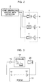
- FIG. 2 shows a typical electronic musical instrument.
- a waveform of music sound is generated by a tone generating circuit (a tone generator) 2.
- An effect for example, echo, reverberation or tremolo
- the resultant musical tone signal is amplified by a power amplifier 4.
- the amplified musical tone signal is radiated into the surrounding space through a plurality of loudspeakers 6.
- the effects except for tremolo caused by loudspeaker rotation for example) are imparted by electrical signal processing, which would restrict naturality of the sound field effects such as echo and reverberation.
- the sound effects are separately imparted for different electronic musical instruments.
- the quality, volume, length, and so on of acoustics (especially, reverberation) differ from one instrument to another, thereby sometimes losing integrity of performance or causing a sense of incongruity.
- FIG. 3 shows a typical acoustic feedback system known as a sound field support apparatus for intensifying the reverberation and spatial impressions of a listening room.
- a loudspeaker 12 and a microphone 14 are spaced apart from each other in a room 10 by an appropriate distance.
- a sound picked up by the microphone 14 is supplied to a FIR (Finite Impulse Response: non-cyclic) filter 18 through a head amplifier 16 to generate a reverberation signal (mainly an initial reflection signal).
- the generated reverberation signal is reproduced from the loudspeaker 12 through a power amplifier 20.
- the reproduced sound is picked up by the microphone 14.
- This loop is repeated to increase the impression of volume (or increase sound pressure), to increase the impression of reverberation (or extend reverberation time), and to increase the impression of space (or intensify a side reflection tone energy).
- FIGS. 4 and 5 A practical sound field controller based on the above-mentioned acoustic feedback system is illustrated in FIGS. 4 and 5.
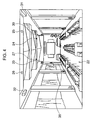
- FIG. 4 shows an example of arrangement of microphones and loudspeakers.
- a listening room 22 such as a music room
- four microphones 24 through 27 are installed on the ceiling
- four loudspeakers 30 through 33 are installed on the walls.
- a controller main 36 for controlling this system in its entirety is constituted as a separate apparatus and arranged inside the room 22.
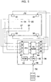
- FIG. 5 is a block diagram illustrating a circuit constitution of this system.
- a tone signal picked up from each of the microphones 24 through 27 is adjusted in frequency characteristics by an equalizer 42 connected to each of head amplifiers 38 through 41 to prevent howling from occurring.
- the adjusted signal is supplied to an FIR filter 44 to provide an initial reflection tone.
- the initial reflection sound or tone is amplified by each of amplifiers 46 through 49.
- the amplified tone is reproduced by each of the loudspeakers 30 through 33.
- a ROM 52 stores initial reflection tone parameters of various sound field patterns. When one of the sound field patterns is selected by an external infrared remote commander 54, a corresponding field sound pattern select signal 56 is transmitted to be received by the apparatus main 36 at a light receiving window 58. Receiving this signal, a CPU 60 reads the initial reflection tone parameter of the corresponding sound field pattern from the ROM 52, and sets this parameter to the FIR filter 44 to set an acoustic space.
- Imparting of reverberation by the sound field support system shown in FIGS. 4 and 5 requires the dedicated loudspeakers 30 through 33.
- This system also requires to install the microphones 24 through 27 and the loudspeakers 30 through 33 on the walls and ceiling of the room 22, to arrange the apparatus main 36 independently, and to wire the signal cables on the walls and ceiling of the room 22, thereby making the scale of the system large and therefore making the installation of the system difficult.
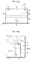
- FIGS. 6(a) and 6(b) show an example of an arrangement of microphones and loudspeakers in the electronic piano, in which FIG. 6(a) is an elevational view and FIG. 6(b) is a side view.
- the electronic piano 62 has a keyboard (a performance operating section) 64 in a front middle portion of the piano.
- Three microphones 68 through 70 are set in a cabinet or frame 66 of the electronic piano 62 with sound receiving sections of these microphones made open to outside. Of these three microphones, the microphones 68 and 69 are spaced from each other on the front left and right sides of the cabinet 66 above the keyboard 64.
- the microphone 70 is arranged at the middle in the horizontal direction of the top plate of the cabinet 66.
- Three loudspeakers 72 through 74 are set in the cabinet 66 with radiation surfaces of the loudspeakers exposed outside. Of these three loudspeakers, the loudspeaker 72 is arranged at the middle in the horizontal direction below the keyboard 64 on the front of the cabinet 66. The loudspeakers 73 and 74 are spaced from each other on the left and right sides of the top plate of the cabinet 66. The signal cables of the microphones 68 through 70 and the loudspeakers 72 through 74 are arranged inside the cabinet 66.
- a musical sound created by the keyboard 64 is reproduced from the loudspeakers 72 through 74.
- the reproduced musical sound and a sound coming from another musical instrument if any are reflected from the walls and ceiling of a room 76, and picked up by the microphones 68 through 70 as shown in FIG. 6 (b).
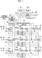
- FIG. 1 is a block diagram illustrating constitution of the circuitry arranged inside the cabinet 66 of the electronic piano 62.
- the signal lines indicated by thick lines belong to regular or ordinary circuit portions of the electronic piano.
- three independent signal paths running from the three microphones 68 through 70 to the loudspeakers 72 through 74 are formed in parallel to each other to constitute three channels.
- a sound source of the electronic piano includes a tone generating circuit 78, a waveform shaping circuit, and an effect processing circuit.
- the tone generating circuit 78 generates a musical tone signal according to performance information inputted from the performance operating section (the keyboard) 64 or according to performance information outputted from a MIDI information source 80 (for example, a magnetic disk device or a optical disk device for reproducing performance information for automatic play).
- a MIDI information source 80 for example, a magnetic disk device or a optical disk device for reproducing performance information for automatic play.
- This apparatus further includes a CPU 160 for controlling various parts and sections of the apparatus, a RAM 151 used as a working area of the CPU 160, a ROM 152 storing program instructions executed by the CPU 160, and a disk drive 153 for receiving a machine readable medium 154 such as a floppy disk storing program instructions executable by the CPU 160.
- a CPU 160 for controlling various parts and sections of the apparatus, a RAM 151 used as a working area of the CPU 160, a ROM 152 storing program instructions executed by the CPU 160, and a disk drive 153 for receiving a machine readable medium 154 such as a floppy disk storing program instructions executable by the CPU 160.
- the inventive music apparatus of FIG. 1 is constructed for introducing a music sound into an acoustic space exemplified by the music room 76 or else, and is equipped with an acoustic feedback system for introducing a reflection sound into the acoustic space.
- an input device in the form of the keyboard 64 or the MIDI information source 80 sequentially provides performance information.
- a sound source including the tone generating circuit 78 generates a music signal representative of the music sound in response to the performance information provided from the input device.
- a plurality of channels of the acoustic feedback system are provided in the music apparatus, and are spatially separate from each other. There are three channels in this embodiment. All the channels have similar structure.
- the first channel is structured by the microphone 68 for collecting a sound from the acoustic space to produce a sound signal representative of the sound introduced into the acoustic space, a processor for processing the sound signal to generate a reflection signal representative of a reflection sound in the acoustic space, a mixer 96 for mixing the reflection signal and the music signal with each other to form a mix signal, and the loudspeaker 72 for acoustically reproducing the mix signal to introduce the music sound and the reflection sound into the acoustic space.
- the processor comprises a Finite Impulse Response filter 88 for filtering the sound signal according to parameters to generate the reflection signal. The parameters continuously and randomly vary so as to average the reflection signals among the plurality of the channels.
- the inventive music apparatus is further provided with a switch device in the form of a switching circuit 86 for dynamically switching the plurality of the channels between a plurality of microphones 68,69 and 70, and a plurality of loudspeakers 72, 73 and 74 such that the microphones 68,69 and 70 are cyclically and interchangeably connected to the loudspeakers 72, 73 and 74.
- the inventive music apparatus further comprises echo cancelers (EC) 104-112 disposed between the plurality of microphones 68,69 and 70 and the plurality of loudspeakers 72, 73 and 74 for canceling direct feedback of sounds from the loudspeakers 72, 73 and 74 to the microphones 68,69 and 70.
- EC echo cancelers
- the sound signal picked up by the microphones 68 through 70 is amplified by head amplifiers 82 through 84, and is inputted in the signal switching circuit 86.
- the switching circuit 86 sequentially switches between combinations of three inputs 1 through 3 and three outputs 1 through 3.
- An example of input/output switching by the signal switching circuit 86 is shown in FIG. 7.
- the signal switching circuit 86 constitutes a type of a level matrix, in which three lines of inputs 1 through 3 are alternately and equally distributed to the three outputs 1 through 3 in a certain period.
- the gain continuously varies according to, for example, a sine curve, a sawtooth wave, or mutually independent random signals satisfying the above-mentioned condition.
- This constitution provides an effect similar to that obtained by sequentially and repetitively alternating the installation positions of the three microphones 68 through 70, thereby leveling the transfer characteristics by spatial averaging to result in reduced coloration and enlarged howling margin.
- the switching period is set to, for example, 1 to 1/2 of the reverberation time of the room used.
- the three lines of the outputs 1 through 3 of the signal switching circuit 86 are inputted in the FIR filters 88 through 90 to generate the reflection sound signals.
- the reflection sound parameters set to the FIR filters 88 through 90 are different from each other. In addition, these parameters are continuously and randomly varied separately along time axis as required as shown in FIG. 8. This variation reduces fluctuation in the frequency characteristics caused by the FIR filters 88 through 90 if these filters are of fixed type, thereby leveling the frequency characteristics, resulting in further reduction in coloration and further enlargement in howling margin.
- the parameter variation along time axis is realized by moving output taps of the FIR filters 88 through 90 in a non-correlated manner in a range of, for example, variation width of 0.25 msec to 5 msec, causing no auditory unnaturalness.
- reflection tone parameters of various types may be stored in the ROM 152, from which a performer selects desired reflection tone parameters to set the selected parameters to the FIR filters 88 through 90.
- the reflection sound signals generated by the FIR filters 88 through 90 are inputted in equalizers 92 through 94, in which undulation unique to frequency characteristics of the room and dependent on the installation positions of the loudspeakers 72 through 74 and the electronic piano 62 is roughly flattened.
- the characteristics of the equalizers 92 through 94 are automatically or manually adjusted for each frequency band so that the peak of the loop gain of each channel becomes -12 dB relative to howling point.
- the reflection sound signals outputted from the equalizers 92 through 94 are added by the mixers 96 through 98 to the musical sound signal outputted from the tone generating circuit 78.
- the resultant mix signals are amplified by power amplifiers 100 through 102, and the amplified signals are reproduced by the loudspeakers 72 through 74.
- the sounds reproduced by the loudspeakers 72 through 74 are reflected from the walls and ceiling of the room 76.
- the reflected sounds are commonly picked up by the microphones 68 through 70, and the collected sounds are processed by the three channels to be reproduced from the loudspeakers 72 through 74 again. This loop occurs repetitively on each channel so as to impart longer reverberation fused with the acoustics inherent to the room 76.
- Echo cancelers 104 through 112 correct a sawtooth filter effect due to a direct feedback loop formed between the loudspeakers 72 through 74 and the microphones 68 through 70.
- the number of paths for feeding back the sounds radiated from the loudspeaker increases, because the physical distance between a sound source point and a sound receiving point is small, thereby causing fluctuation in the frequency characteristics of the loop gain.
- the characteristics of the echo cancelers 104 through 112 are adjusted to a response near -F( ⁇ ) to cancel the direct feedback loop between the loudspeakers 72 through 74 and the microphones 68 through 70 and to cancel a feedback loop corresponding to a primary reflection sound (especially when the electronic piano is located by a window of the room), namely the initial portion of an impulse response by acoustic feedback.
- the echo cancelers 104 through 112 may be constituted by adaptive filters to adjust the frequency characteristics automatically.
- the echo cancelers 104 through 112 may be adjusted after installing of the electronic piano 62 in the room 76.
- the echo cancelers 104 through 112 may be adjusted by generating an impulse noise by the tone generating circuit 78, then reproducing the generated impulse noise from the loudspeakers 72 through 74, picking up the reproduced impulse noise by the microphones 68 through 70, measuring an impulse response of the picked up impulse noise, and manually or automatically adjusting the parameters of the echo cancelers 104 through 112 to generally - F( ⁇ ) such that the initial portion of the impulse response is canceled.
- the equalizers 92 through 94 and the echo cancelers 104 through 112 may be adjusted by first step of automatically or manually adjusting the equalizers 92 through 94 at the initial stage of adjustment process for example and then second step of automatically or manually adjusting the echo cancelers 104 through 112. Further, the equalizers 92 through 94 may be automatically or manually adjusted finely (readjustment) while or after automatically or manually adjusting the echo cancelers 104 through 112.
- the plurality of mutually independent signal paths are constituted from the microphones 68 through 70 to the loudspeakers 72 through 74, and the leveling effect (the addition in squared sound pressure area) that cannot be obtained by simple sound pressure addition (so-called mixing) is obtained according to the invention.
- the transfer characteristic between the microphones 68 through 70 and the loudspeakers 72 through 74 is leveled more significantly by the switching of the signal paths by the signal switching circuit 86 and the time-dependent processing of the reflection parameters in the FIR filters 88 through 90, and the echo cancelers 104 through 112, thereby significantly reducing coloration and enlarging howling margin.
- the same acoustics are imparted to both of the musical sound generated by the electronic piano 62 itself and the external sound picked up from the outside by the microphones 68 through 70.
- the same acoustics are imparted to the music sounds of all instruments, thereby providing the natural sound field effect.
- the musical sound reproducing loudspeakers 72 through 74 of the electronic piano 62 also serve as the loudspeakers for the acoustic feedback system, the number of loudspeakers as a whole can be reduced, resulting in the simplified constitution.
- the above-mentioned components are integrally assembled in the cabinet 66 of the electronic piano 62, installation and transportation of the sound field controller are significantly facilitated.
- an ensemble signal provided from another musical instrument may be inputted directly into the three channels by the adders 120 through 122 as indicated by dashed lines shown in FIG. 1.
- three channels are provided. It will be apparent that more than three channels may be provided.
- the present invention is applied to the electronic piano. It will be apparent that the present invention is also applicable to an electronic keyboard instrument of another type and a non-keyboard electronic musical instrument.
- the inventive apparatus 1 is constructed for controlling a sound field.
- input means is composed of the keyboard 64 or the MIDI information source 80 for sequentially providing performance information.
- Generator means is composed of the tone generating circuit 78 for generating a music signal representative of a music sound in response to the performance information provided from the input means.
- the plurality of microphones 68, 69 and 70 are arranged separately from each other. Each microphone collects a sound introduced into the sound field to produce a sound signal representative of the sound introduced into the sound field.
- Processor means is provided in the form of the FIR filters 88, 89 and 90 for processing each sound signal produced by each microphone to generate each reflection signal representative of a reflection sound in the sound field.
- Mixer means is composed of the mixers 96, 97 and 98 for mixing each reflection signal and the music signal with each other to form each mix signal.
- the plurality of loudspeakers 72, 73 and 74 are arranged separately from each other. Each loudspeaker acoustically reproduces each mix signal to introduce the music sound and the reflection sound into the sound field.
- the processor means comprises the Finite Impulse Response filter 88, 89 or 90 that filters the sound signal according to parameters to generate the reflection signal. The parameters continuously and randomly vary so as to average the reflection signals among the plurality of the microphones 68, 69 and 70.
- the inventive apparatus further comprises switch means in the form of the switching circuit 86 for switching paths of signals between the plurality of the microphones 68, 69 and 70, and the plurality of the loudspeakers 72, 73 and 74 such that the microphones are cyclically and interchangeably connected to the loudspeakers.
- the inventive apparatus further comprises canceler means in the form of the echo cancelers 104-112 disposed between the microphones 68, 69 and 70 and the loudspeakers 72, 73 and 74 for canceling direct feedback of sounds from the loudspeakers to the microphones.
- the inventive apparatus further comprises the frame 66 for accommodating therein the input means, the generator means, the microphones and the loudspeakers to constitute an electronic musical instrument in the form of the electronic piano 62 for introducing the music sound into the sound field or room 76.
- the electronic musical instrument is installed with an acoustic feedback system composed of the microphones and the processor means in combination with the loudspeakers to introduce the reflection sound into the sound field.
- the microphones collect another music sound introduced into the sound field by another musical instrument in addition to the music sound produced by the electronic musical instrument so as to enhance an ensemble of the electronic musical instrument and said another musical instrument.
- the input means may comprise a music play implement of the electronic musical instrument manipulated to provide the performance information.
- the machine readable medium 154 is used in the music apparatus having the CPU 160 for introducing a music sound and a reflection sound into a sound field by means of the plurality of microphones 68, 69 and 70 arranged separately from each other and the plurality of loudspeakers 72, 73 and 74 arranged separately from each other.
- the medium 154 contains program instructions executable by the CPU 160 for causing the music apparatus to perform the steps of sequentially providing performance information, generating a music signal representative of the music sound in response to the performance information, operating each microphone to collect a sound from the sound field to produce a sound signal representative of the sound introduced into the sound field, processing each sound signal produced by each microphone to generate each reflection signal representative of a reflection sound in the sound field, mixing each reflection signal and the music signal with each other to form each mix signal, and operating each loudspeaker to acoustically reproduce each mix signal to introduce the music sound and the reflection sound into the sound field.
- the steps performed by the music apparatus further comprise switching paths of signals between the plurality of the microphones and the plurality of the loudspeakers such that the microphones are cyclically and interchangeably connected to the loudspeakers.
- the steps performed by the music apparatus further comprise canceling direct feedback of sounds from the loudspeakers to the microphones.
- the invention relates to an apparatus for controlling a sound field, comprising: input means for sequentially providing performance information; generator means for generating a music signal; a plurality of microphones; and processor means for processing each sound signal produced by each microphone.
Landscapes
- Physics & Mathematics (AREA)
- Engineering & Computer Science (AREA)
- Acoustics & Sound (AREA)
- Multimedia (AREA)
- Circuit For Audible Band Transducer (AREA)
- Reverberation, Karaoke And Other Acoustics (AREA)
- Stereophonic System (AREA)
- Electrophonic Musical Instruments (AREA)
Applications Claiming Priority (3)
| Application Number | Priority Date | Filing Date | Title |
|---|---|---|---|
| JP6386697 | 1997-03-03 | ||
| JP06386697A JP3175622B2 (ja) | 1997-03-03 | 1997-03-03 | 演奏音場制御装置 |
| JP63866/97 | 1997-03-03 |
Publications (2)
| Publication Number | Publication Date |
|---|---|
| EP0865025A1 true EP0865025A1 (fr) | 1998-09-16 |
| EP0865025B1 EP0865025B1 (fr) | 2003-07-09 |
Family
ID=13241669
Family Applications (1)
| Application Number | Title | Priority Date | Filing Date |
|---|---|---|---|
| EP98103717A Expired - Lifetime EP0865025B1 (fr) | 1997-03-03 | 1998-03-03 | Appareil avec haut-parleurs pour générer simultanément de la musique et du son réfléchi |
Country Status (4)
| Country | Link |
|---|---|
| US (1) | US6157724A (fr) |
| EP (1) | EP0865025B1 (fr) |
| JP (1) | JP3175622B2 (fr) |
| DE (1) | DE69816155T2 (fr) |
Cited By (5)
| Publication number | Priority date | Publication date | Assignee | Title |
|---|---|---|---|---|
| WO1999054867A1 (fr) * | 1998-04-23 | 1999-10-28 | Industrial Research Limited | Systeme augmentant la reflexion precoce en ligne, pour l'amelioration de l'acoustique |
| CN101064974B (zh) * | 2006-04-28 | 2012-05-23 | 雅马哈株式会社 | 声场控制装置 |
| US8515106B2 (en) | 2007-11-28 | 2013-08-20 | Qualcomm Incorporated | Methods and apparatus for providing an interface to a processing engine that utilizes intelligent audio mixing techniques |
| US8660280B2 (en) | 2007-11-28 | 2014-02-25 | Qualcomm Incorporated | Methods and apparatus for providing a distinct perceptual location for an audio source within an audio mixture |
| KR20150088169A (ko) * | 2014-01-23 | 2015-07-31 | 강릉원주대학교산학협력단 | 소음 제어 및 감쇄 유도를 위한 장치 및 방법 |
Families Citing this family (37)
| Publication number | Priority date | Publication date | Assignee | Title |
|---|---|---|---|---|
| US6751202B1 (en) | 1999-04-30 | 2004-06-15 | 3Com Corporation | Filtered transmit cancellation in a full-duplex modem data access arrangement (DAA) |
| JP3823824B2 (ja) | 2001-12-27 | 2006-09-20 | ヤマハ株式会社 | 電子楽音発生装置および信号処理特性調整方法 |
| JP3858694B2 (ja) * | 2001-12-28 | 2006-12-20 | ヤマハ株式会社 | 電子鍵盤楽器の楽音再生方法および電子鍵盤楽器 |
| JP3843841B2 (ja) | 2002-01-10 | 2006-11-08 | ヤマハ株式会社 | 電子楽器 |
| US7474753B2 (en) * | 2003-08-28 | 2009-01-06 | Yamaha Corporation | Sound field control apparatus, signal processing apparatus, sound field control program, and signal processing program |
| US7184557B2 (en) | 2005-03-03 | 2007-02-27 | William Berson | Methods and apparatuses for recording and playing back audio signals |
| US7783594B1 (en) * | 2005-08-29 | 2010-08-24 | Evernote Corp. | System and method for enabling individuals to select desired audio |
| JP4752403B2 (ja) * | 2005-09-06 | 2011-08-17 | ヤマハ株式会社 | 拡声システム |
| JP4973315B2 (ja) * | 2007-05-25 | 2012-07-11 | ヤマハ株式会社 | 音響障害除去方法及び音場支援システム |
| US8239047B1 (en) | 2009-07-15 | 2012-08-07 | Bryan Bergeron | Systems and methods for indirect control of processor enabled devices |
| US9067132B1 (en) | 2009-07-15 | 2015-06-30 | Archetype Technologies, Inc. | Systems and methods for indirect control of processor enabled devices |
| JP5540907B2 (ja) * | 2010-06-03 | 2014-07-02 | ヤマハ株式会社 | 音場支援装置 |
| US8884150B2 (en) * | 2012-08-03 | 2014-11-11 | The Penn State Research Foundation | Microphone array transducer for acoustical musical instrument |
| US9264524B2 (en) | 2012-08-03 | 2016-02-16 | The Penn State Research Foundation | Microphone array transducer for acoustic musical instrument |
| US9368101B1 (en) * | 2012-10-19 | 2016-06-14 | Meyer Sound Laboratories, Incorporated | Dynamic acoustic control system and method for hospitality spaces |
| US9280964B2 (en) * | 2013-03-14 | 2016-03-08 | Fishman Transducers, Inc. | Device and method for processing signals associated with sound |
| US9554207B2 (en) | 2015-04-30 | 2017-01-24 | Shure Acquisition Holdings, Inc. | Offset cartridge microphones |
| US9565493B2 (en) | 2015-04-30 | 2017-02-07 | Shure Acquisition Holdings, Inc. | Array microphone system and method of assembling the same |
| IT201600131975A1 (it) * | 2016-12-29 | 2018-06-29 | Third House Srls | Sistema e metodo di riproduzione del suono di un’orchestra |
| US10367948B2 (en) | 2017-01-13 | 2019-07-30 | Shure Acquisition Holdings, Inc. | Post-mixing acoustic echo cancellation systems and methods |
| CN112335261B (zh) | 2018-06-01 | 2023-07-18 | 舒尔获得控股公司 | 图案形成麦克风阵列 |
| JP6503121B1 (ja) | 2018-07-31 | 2019-04-17 | 三澤 みよ子 | 音声制御装置、その方法、そのプログラム |
| US11310596B2 (en) | 2018-09-20 | 2022-04-19 | Shure Acquisition Holdings, Inc. | Adjustable lobe shape for array microphones |
| US11558693B2 (en) | 2019-03-21 | 2023-01-17 | Shure Acquisition Holdings, Inc. | Auto focus, auto focus within regions, and auto placement of beamformed microphone lobes with inhibition and voice activity detection functionality |
| JP7572964B2 (ja) | 2019-03-21 | 2024-10-24 | シュアー アクイジッション ホールディングス インコーポレイテッド | 阻止機能を伴うビーム形成マイクロフォンローブの自動集束、領域内自動集束、および自動配置 |
| TW202101422A (zh) | 2019-05-23 | 2021-01-01 | 美商舒爾獲得控股公司 | 可操縱揚聲器陣列、系統及其方法 |
| WO2020243471A1 (fr) | 2019-05-31 | 2020-12-03 | Shure Acquisition Holdings, Inc. | Automélangeur à faible latence, à détection d'activité vocale et de bruit intégrée |
| CN114467312A (zh) | 2019-08-23 | 2022-05-10 | 舒尔获得控股公司 | 具有改进方向性的二维麦克风阵列 |
| US12028678B2 (en) | 2019-11-01 | 2024-07-02 | Shure Acquisition Holdings, Inc. | Proximity microphone |
| US11552611B2 (en) | 2020-02-07 | 2023-01-10 | Shure Acquisition Holdings, Inc. | System and method for automatic adjustment of reference gain |
| USD944776S1 (en) | 2020-05-05 | 2022-03-01 | Shure Acquisition Holdings, Inc. | Audio device |
| US11706562B2 (en) | 2020-05-29 | 2023-07-18 | Shure Acquisition Holdings, Inc. | Transducer steering and configuration systems and methods using a local positioning system |
| US12452584B2 (en) | 2021-01-29 | 2025-10-21 | Shure Acquisition Holdings, Inc. | Scalable conferencing systems and methods |
| US12542123B2 (en) | 2021-08-31 | 2026-02-03 | Shure Acquisition Holdings, Inc. | Mask non-linear processor for acoustic echo cancellation |
| US12289584B2 (en) | 2021-10-04 | 2025-04-29 | Shure Acquisition Holdings, Inc. | Networked automixer systems and methods |
| EP4427465A1 (fr) | 2021-11-05 | 2024-09-11 | Shure Acquisition Holdings, Inc. | Algorithme distribué pour auto-mélange de la parole sur des réseaux sans fil |
| US12598261B2 (en) | 2022-09-28 | 2026-04-07 | Shure Acquisition Holdings, Inc. | Wideband doubletalk detection for optimization of acoustic echo cancellation |
Citations (6)
| Publication number | Priority date | Publication date | Assignee | Title |
|---|---|---|---|---|
| US2199702A (en) * | 1938-01-29 | 1940-05-07 | Hammond Laurens | Method of broadcasting |
| US4058045A (en) * | 1976-02-05 | 1977-11-15 | Solosonic | Piano with sound-enhancing system |
| DE3424754A1 (de) * | 1984-07-05 | 1986-01-16 | Dr. Rainer Böhm GmbH & Co KG, 4950 Minden | Elektronische orgel |
| JPS61296896A (ja) * | 1985-06-25 | 1986-12-27 | Nippon Gakki Seizo Kk | 反射音および残響音形成装置 |
| JPH06186966A (ja) * | 1992-12-21 | 1994-07-08 | Casio Comput Co Ltd | エフェクタ |
| JPH07175468A (ja) * | 1993-12-17 | 1995-07-14 | Kawai Musical Instr Mfg Co Ltd | アコースティック・電子複合ピアノ |
Family Cites Families (8)
| Publication number | Priority date | Publication date | Assignee | Title |
|---|---|---|---|---|
| JPS60138396A (ja) * | 1983-12-26 | 1985-07-23 | Matsushita Electric Ind Co Ltd | 熱交換器 |
| NL8900571A (nl) * | 1989-03-09 | 1990-10-01 | Prinssen En Bus Holding Bv | Electro-akoestisch systeem. |
| JPH042928A (ja) * | 1990-04-19 | 1992-01-07 | Matsushita Electric Ind Co Ltd | 音場制御装置 |
| JP3173814B2 (ja) * | 1991-05-30 | 2001-06-04 | 株式会社タムラ製作所 | フラックス塗布方法 |
| JPH05318513A (ja) * | 1992-05-15 | 1993-12-03 | Akebono Brake Ind Co Ltd | パッドの熱プレス型 |
| JP2737595B2 (ja) * | 1993-03-26 | 1998-04-08 | ヤマハ株式会社 | 音場制御装置 |
| JPH084243B2 (ja) * | 1993-05-31 | 1996-01-17 | 日本電気株式会社 | 多チャンネルエコー除去方法および装置 |
| JP3351905B2 (ja) * | 1994-07-28 | 2002-12-03 | ソニー株式会社 | 音声信号処理装置 |
-
1997
- 1997-03-03 JP JP06386697A patent/JP3175622B2/ja not_active Expired - Fee Related
-
1998
- 1998-03-03 EP EP98103717A patent/EP0865025B1/fr not_active Expired - Lifetime
- 1998-03-03 US US09/033,971 patent/US6157724A/en not_active Expired - Lifetime
- 1998-03-03 DE DE69816155T patent/DE69816155T2/de not_active Expired - Lifetime
Patent Citations (6)
| Publication number | Priority date | Publication date | Assignee | Title |
|---|---|---|---|---|
| US2199702A (en) * | 1938-01-29 | 1940-05-07 | Hammond Laurens | Method of broadcasting |
| US4058045A (en) * | 1976-02-05 | 1977-11-15 | Solosonic | Piano with sound-enhancing system |
| DE3424754A1 (de) * | 1984-07-05 | 1986-01-16 | Dr. Rainer Böhm GmbH & Co KG, 4950 Minden | Elektronische orgel |
| JPS61296896A (ja) * | 1985-06-25 | 1986-12-27 | Nippon Gakki Seizo Kk | 反射音および残響音形成装置 |
| JPH06186966A (ja) * | 1992-12-21 | 1994-07-08 | Casio Comput Co Ltd | エフェクタ |
| JPH07175468A (ja) * | 1993-12-17 | 1995-07-14 | Kawai Musical Instr Mfg Co Ltd | アコースティック・電子複合ピアノ |
Non-Patent Citations (3)
| Title |
|---|
| PATENT ABSTRACTS OF JAPAN vol. 011, no. 165 (E - 510) 27 May 1987 (1987-05-27) * |
| PATENT ABSTRACTS OF JAPAN vol. 018, no. 536 (P - 1811) 12 October 1994 (1994-10-12) * |
| PATENT ABSTRACTS OF JAPAN vol. 095, no. 010 30 November 1995 (1995-11-30) * |
Cited By (5)
| Publication number | Priority date | Publication date | Assignee | Title |
|---|---|---|---|---|
| WO1999054867A1 (fr) * | 1998-04-23 | 1999-10-28 | Industrial Research Limited | Systeme augmentant la reflexion precoce en ligne, pour l'amelioration de l'acoustique |
| CN101064974B (zh) * | 2006-04-28 | 2012-05-23 | 雅马哈株式会社 | 声场控制装置 |
| US8515106B2 (en) | 2007-11-28 | 2013-08-20 | Qualcomm Incorporated | Methods and apparatus for providing an interface to a processing engine that utilizes intelligent audio mixing techniques |
| US8660280B2 (en) | 2007-11-28 | 2014-02-25 | Qualcomm Incorporated | Methods and apparatus for providing a distinct perceptual location for an audio source within an audio mixture |
| KR20150088169A (ko) * | 2014-01-23 | 2015-07-31 | 강릉원주대학교산학협력단 | 소음 제어 및 감쇄 유도를 위한 장치 및 방법 |
Also Published As
| Publication number | Publication date |
|---|---|
| EP0865025B1 (fr) | 2003-07-09 |
| US6157724A (en) | 2000-12-05 |
| DE69816155T2 (de) | 2004-04-22 |
| JP3175622B2 (ja) | 2001-06-11 |
| DE69816155D1 (de) | 2003-08-14 |
| JPH10247089A (ja) | 1998-09-14 |
Similar Documents
| Publication | Publication Date | Title |
|---|---|---|
| US6157724A (en) | Apparatus having loudspeakers concurrently producing music sound and reflection sound | |
| EP0762801B1 (fr) | Système de haut-parleur non directionnel avec source sonore pontuelle | |
| US5025472A (en) | Reverberation imparting device | |
| JP3823824B2 (ja) | 電子楽音発生装置および信号処理特性調整方法 | |
| EP0335468A1 (fr) | Système électro-acoustique | |
| JP6157641B2 (ja) | 電子式周回スピーカにおけるセレストのための装置および方法 | |
| US6888058B2 (en) | Electronic musical instrument | |
| CA1338084C (fr) | Systeme de reproduction sonore stereophonique multidimensionnelle | |
| US20040234093A1 (en) | Sound output system | |
| JPH10304498A (ja) | ステレオ拡大装置及び音場拡大装置 | |
| JP2006513656A (ja) | サウンドを発生させるための装置および方法 | |
| US5686684A (en) | Effect adaptor attachable to karaoke machine to create harmony chorus | |
| JP2886402B2 (ja) | ステレオ信号発生装置 | |
| US10755693B2 (en) | Acoustic apparatus and vibration transmission method | |
| EP3869502B1 (fr) | Procédé et dispositif de traitement de signal sonore | |
| JPH0937399A (ja) | ヘッドホン装置 | |
| US6399868B1 (en) | Sound effect generator and audio system | |
| JP3287970B2 (ja) | 残響音付加方法および装置 | |
| JP2001228867A (ja) | 演奏音場制御装置 | |
| JPH0662486A (ja) | 音響再生装置 | |
| EP3869501B1 (fr) | Procédé et dispositif de traitement de signal sonore | |
| JP3206770B2 (ja) | 楽音発生装置 | |
| JPH04328796A (ja) | 電子楽器 | |
| JP4254690B2 (ja) | 室内音響生成装置 | |
| DE69613524T2 (de) | Nicht-gerichtetes Lautsprechersystem mit punktueller Schallquelle |
Legal Events
| Date | Code | Title | Description |
|---|---|---|---|
| PUAI | Public reference made under article 153(3) epc to a published international application that has entered the european phase |
Free format text: ORIGINAL CODE: 0009012 |
|
| AK | Designated contracting states |
Kind code of ref document: A1 Designated state(s): DE FR GB |
|
| AX | Request for extension of the european patent |
Free format text: AL;LT;LV;MK;RO;SI |
|
| 17P | Request for examination filed |
Effective date: 19990301 |
|
| AKX | Designation fees paid |
Free format text: DE FR GB |
|
| RBV | Designated contracting states (corrected) |
Designated state(s): DE FR GB |
|
| 17Q | First examination report despatched |
Effective date: 20020212 |
|
| GRAH | Despatch of communication of intention to grant a patent |
Free format text: ORIGINAL CODE: EPIDOS IGRA |
|
| GRAH | Despatch of communication of intention to grant a patent |
Free format text: ORIGINAL CODE: EPIDOS IGRA |
|
| GRAA | (expected) grant |
Free format text: ORIGINAL CODE: 0009210 |
|
| AK | Designated contracting states |
Designated state(s): DE FR GB |
|
| REG | Reference to a national code |
Ref country code: GB Ref legal event code: FG4D |
|
| REF | Corresponds to: |
Ref document number: 69816155 Country of ref document: DE Date of ref document: 20030814 Kind code of ref document: P |
|
| PLBE | No opposition filed within time limit |
Free format text: ORIGINAL CODE: 0009261 |
|
| STAA | Information on the status of an ep patent application or granted ep patent |
Free format text: STATUS: NO OPPOSITION FILED WITHIN TIME LIMIT |
|
| ET | Fr: translation filed | ||
| 26N | No opposition filed |
Effective date: 20040414 |
|
| PGFP | Annual fee paid to national office [announced via postgrant information from national office to epo] |
Ref country code: FR Payment date: 20130325 Year of fee payment: 16 |
|
| REG | Reference to a national code |
Ref country code: FR Ref legal event code: ST Effective date: 20141128 |
|
| PG25 | Lapsed in a contracting state [announced via postgrant information from national office to epo] |
Ref country code: FR Free format text: LAPSE BECAUSE OF NON-PAYMENT OF DUE FEES Effective date: 20140331 |
|
| PGFP | Annual fee paid to national office [announced via postgrant information from national office to epo] |
Ref country code: DE Payment date: 20150224 Year of fee payment: 18 |
|
| PGFP | Annual fee paid to national office [announced via postgrant information from national office to epo] |
Ref country code: GB Payment date: 20150225 Year of fee payment: 18 |
|
| REG | Reference to a national code |
Ref country code: DE Ref legal event code: R119 Ref document number: 69816155 Country of ref document: DE |
|
| GBPC | Gb: european patent ceased through non-payment of renewal fee |
Effective date: 20160303 |
|
| PG25 | Lapsed in a contracting state [announced via postgrant information from national office to epo] |
Ref country code: DE Free format text: LAPSE BECAUSE OF NON-PAYMENT OF DUE FEES Effective date: 20161001 Ref country code: GB Free format text: LAPSE BECAUSE OF NON-PAYMENT OF DUE FEES Effective date: 20160303 |