EP0865340B1 - Verfahren zum schweissverbinden von zwei elementen - Google Patents
Verfahren zum schweissverbinden von zwei elementen Download PDFInfo
- Publication number
- EP0865340B1 EP0865340B1 EP96935612A EP96935612A EP0865340B1 EP 0865340 B1 EP0865340 B1 EP 0865340B1 EP 96935612 A EP96935612 A EP 96935612A EP 96935612 A EP96935612 A EP 96935612A EP 0865340 B1 EP0865340 B1 EP 0865340B1
- Authority
- EP
- European Patent Office
- Prior art keywords
- hole
- shaped means
- cup
- substantially cup
- shaped
- Prior art date
- Legal status (The legal status is an assumption and is not a legal conclusion. Google has not performed a legal analysis and makes no representation as to the accuracy of the status listed.)
- Expired - Lifetime
Links
Images


Classifications
-
- B—PERFORMING OPERATIONS; TRANSPORTING
- B23—MACHINE TOOLS; METAL-WORKING NOT OTHERWISE PROVIDED FOR
- B23K—SOLDERING OR UNSOLDERING; WELDING; CLADDING OR PLATING BY SOLDERING OR WELDING; CUTTING BY APPLYING HEAT LOCALLY, e.g. FLAME CUTTING; WORKING BY LASER BEAM
- B23K9/00—Arc welding or cutting
- B23K9/23—Arc welding or cutting taking account of the properties of the materials to be welded
- B23K9/232—Arc welding or cutting taking account of the properties of the materials to be welded of different metals
-
- B—PERFORMING OPERATIONS; TRANSPORTING
- B23—MACHINE TOOLS; METAL-WORKING NOT OTHERWISE PROVIDED FOR
- B23K—SOLDERING OR UNSOLDERING; WELDING; CLADDING OR PLATING BY SOLDERING OR WELDING; CUTTING BY APPLYING HEAT LOCALLY, e.g. FLAME CUTTING; WORKING BY LASER BEAM
- B23K26/00—Working by laser beam, e.g. welding, cutting or boring
- B23K26/20—Bonding
- B23K26/32—Bonding taking account of the properties of the material involved
- B23K26/324—Bonding taking account of the properties of the material involved involving non-metallic parts
-
- F—MECHANICAL ENGINEERING; LIGHTING; HEATING; WEAPONS; BLASTING
- F16—ENGINEERING ELEMENTS AND UNITS; GENERAL MEASURES FOR PRODUCING AND MAINTAINING EFFECTIVE FUNCTIONING OF MACHINES OR INSTALLATIONS; THERMAL INSULATION IN GENERAL
- F16B—DEVICES FOR FASTENING OR SECURING CONSTRUCTIONAL ELEMENTS OR MACHINE PARTS TOGETHER, e.g. NAILS, BOLTS, CIRCLIPS, CLAMPS, CLIPS OR WEDGES; JOINTS OR JOINTING
- F16B5/00—Joining sheets or plates, e.g. panels, to one another or to strips or bars parallel to them
- F16B5/08—Joining sheets or plates, e.g. panels, to one another or to strips or bars parallel to them by means of welds or the like
-
- B—PERFORMING OPERATIONS; TRANSPORTING
- B23—MACHINE TOOLS; METAL-WORKING NOT OTHERWISE PROVIDED FOR
- B23K—SOLDERING OR UNSOLDERING; WELDING; CLADDING OR PLATING BY SOLDERING OR WELDING; CUTTING BY APPLYING HEAT LOCALLY, e.g. FLAME CUTTING; WORKING BY LASER BEAM
- B23K2103/00—Materials to be soldered, welded or cut
- B23K2103/02—Iron or ferrous alloys
- B23K2103/04—Steel or steel alloys
-
- B—PERFORMING OPERATIONS; TRANSPORTING
- B23—MACHINE TOOLS; METAL-WORKING NOT OTHERWISE PROVIDED FOR
- B23K—SOLDERING OR UNSOLDERING; WELDING; CLADDING OR PLATING BY SOLDERING OR WELDING; CUTTING BY APPLYING HEAT LOCALLY, e.g. FLAME CUTTING; WORKING BY LASER BEAM
- B23K2103/00—Materials to be soldered, welded or cut
- B23K2103/30—Organic materials
- B23K2103/42—Plastics other than composite materials
Definitions
- the present application relates to the a method for attaching a first element of a first material to a second element of a second material by a welding process, said first element being connected to a third element of said second material, which third element is brought in contact with said second element, whereafter said third element is welded to said second element through a throughgoing hole in said first element.
- SE-B-309 352 there is known a welding technique for welding a lining in a container, there being used sleeveshaped connection elements, also known from SE-B-309 526.
- DE-A1-20 10 785 discloses welding of different metals, especially steel which has been covered by titanium or zirconium.
- US 2 985 747 relates to a method for attaching a titanium object to an iron containing metal main body, said iron containing metal main body having inserted thereinto an inlayt of vanadium, whereafter a hole is made in said titanium object for welding said titanium object through said hole to said vanadium inlay.
- the invention relates to the design and mounting of a body which is weldable to a main structure, for example of steel, and which is the carrier element for a third material which cannot be welded to steel.
- An object of the present invention is to provide a welding method wherein the element is of low weight, said element being easy to mount in automatic equipement, and said element being able to withstand loads prior to the welding, i.e. the pressing out force being sufficiently high.
- said third element is shaped substantially as a cup-shaped means having an extending collar at its open end, said means being arranged with a tight fit in said hole, and whereafter the bottom of said substantially cup-shaped means is welded to said second element.
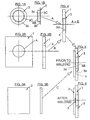
- Figures 1A and 1B illustrate a top view and a side view, respectively, of a substantially cup-shaped means having a collar extending from its open end.
- Figures 2A and 2B illustrate a plan view and a side view, respectively, of a first element of a first material provided with a throughgoing hole.
- Figures 3A and 3B illustrate a plan view and a side view, respectively, of a second element of a second material which is to be welded to said first element.
- Fig. 4 is a side view illustrating the substantially cup-shaped means arranged in the hole of said first element.
- Fig. 5 is a side view illustrating said second element being placed in close proximity of said first element and in close proximity to the bottom of said substantially cup-shaped means arranged in the hole thereof.
- Fig. 6 is a side view similarly to Fig. 5, and illustrates said first element, the substantially cup-shaped means arranged therein, as well as said second element welded to the bottom of said substantially cup-shaped means.
- Figures 7A and 7B illustrate perspective views of a second embodiment of a substantially cup-shaped means and an associated first element, respectively, especially adapted for taking large torque moments.
- Fig. 8 is a perspective view illustrating the substantially cup-shaped means of Fig. 7A assembled in the first element of Fig. 7B.
- Fig. 9 is a longitudinal section taken along the lines IX-IX of Fig. 8.
- Fig. 10 is a perspective view illustrating still another embodiment of a substantially cup-shaped means having a specific collar shape, mounted in a hole in a first element.
- Fig. 11 is a longitudinal section through still another embodiment of a cup-shaped means being adapted to a first element having varying plate thickness or being composed of several elements of various dimensions.
- Fig. 12 is a longitudinal section through yet another embodiment of a substantially cup-shaped means having a specific bottom portion contributing in a favourable holding effect when being arranged in an associated first element.
- Figures 13A and 13B illustrate a top view and a longitudinal section taken along the lines XIIIB-XIIIB in Fig. 13A, respectively, of still another embodiment of a substantially cup-shaped means, here being designed as a double means having a specific intermediate portion therebetween.
- Fig. 14A is a perspective view of another embodiment of a substantially cup-shaped means according to the present invention.
- Fig. 14B is a longitudinal section through an embodiment of a substantially cup-shaped means as illustrated in Fig. 14A, arranged in an associated first element and being provided with a unique collar for further attachment to said first element.
- Fig. 15A is another embodiment of a substantially cup-shaped means according to the present invention, provided with still another unique collar.
- Fig. 15B is a longitudinal section through the embodiment of the means illustrated in Fig. 15A arranged in a throughgoing hole in an associated first element, said unique collar being arranged for further attachment to said first element or possibly to an intermediate element in further association therewith.
- Figures 1-6 there are illustrated the various parts which can be included in an embodiment of a method according to the present invention, namely a method for attaching a first element 1 of a first material, see Figures 2A and 2B, to a second element 2 of a second material, see Figures 3A and 3B, by a welding process, the materials of said two elements 1 and 2, respectively, being substantially non-weldable to each other.
- FIGs 1A and 1B there is illustrated a top view and a side view of a third element 3 which is of the same material as said second element 2, which third element 3 is shaped substantially as a cup-shaped means 3a having an extending collar 3b at its open end 3c.
- This third element 3 see arrows A and B, will be placed with a tight fit in a hole 4, made in said first element 1, see Fig. 4, wherein said first element 1 and said third element 3 have been mounted together.
- the second element 2 can thereafter be is brought in position against an opposit surface of said first element 1, i.e. said second element 2 is brought in contact with said first element 1 and in contact with the bottom 3d of said third element 3, see Fig. 5, which illustrate an assembly just prior to the commencement of the welding process.
- first element 1 and said second element 2 cannot be welded to each other, said first element being of a material which for example cannot be welded to steel, whereas element 2 and said cup-shaped means 3 can be made of for example steel.
- Fig. 7A there is illustrated in a perspective view another embodiment of a substantially cup-shaped third element 103, which third element 103 also here takes the form of a substantially cup-shaped means 103a having an upper extending collar 103b surrounding a multi-edged open end 103c and a corresponding bottom 103d.
- FIG. 7B there is illustrated perspectively a further embodiment of a first element 101 of a first material being provided with a throughgoing hole 104 having a plurality of straight edges, adapted to letting the substantially cup-shaped means 103c of Fig. 7A be located therein with a snug fit, as this is further illustrated in Figures 8 and 9.
- the multi-edged shape of the third element 103 fitting into the multi-edged hole 104 in said first element 101 will be specifically favourable in connection with the attachment to a second element and wherein the attachement will be subjected to larger torque forces.
- Fig. 10 there is illustrated still another embodiment of a substantially cup-shaped third element 203 having an extending collar 203b made of sharp teeth or prongs which can contribute to a further attachment when sid cup-shaped means 203 is put in position in a throughgoing hole 204 in a second element 201, the location therein still being effected with a snug fit.
- Fig. 11 there is illustrated a section through yet another embodiment of a substantially cup-shaped element 303, said element having a cup-shaped means 303a provided with a collar of varying dimension, for example a collar portion 303b having a thicker dimension and another collar portion 303b' having a smaller dimension.
- Said cup-shaped element 303 can for example being adapted to fit into a hole in a first element 301 having various thickness, for example a first thickness 301a and a second thickness 301b, or possibly being adapted to first elements being constituted by two or more pieces.
- a third element 403 being positioned in a first element 401, namely in a throughgoing hole 404 made in said first element 401.
- the bottom portion 403d may appropriately be pressed into circumferentially extending recesses 404a of the bottom portion of said hole 404 in said first element 401, for further locking therein prior to the welding to a previously discussed second element (not illustrated).
- FIG. 13A and 13B there are illustrated a top view and a section through the lines XIIIB-XIIIB in Fig. 13A, respectively, of yet another embodiment of a third element 503, which still is substantially cup-shaped, but here with an embodiment including pairs of cup-shaped elements 503A and 503B, respectively.
- Each pair of substantially cup-shaped elements 503A and 503B are tied together by an intermediate part 507 being of substantially the same thickness as the collar portion 503b of each pair of elements 503A and 503B, and being provided with a hole 508 therein.
- the bottom portion 503d of each cup-shaped element 503A and 503B may be somewhat bulged and/or somewhat flexible, depending on the field of application.
- pairs of substantially cup-shaped elements can be affixed in corresponding holes in a second element (not illustrated) and with a snug fit.
- pairs of third elements 503A and 503B could equally well be arranged in appropriate holes through pairs of first elements, such pairs of elements or any other number of elements being held together and being welded to said previously discussed second elements (not illustrated), with or without a further attachment means through said hole 508 in the intermediate portion 507 between said cup-shaped elements 503A and 503B.
- FIG. 14A there is perspectively illustrated yet another embodiment of a substantially cup-shaped third element 603 including a cup-shaped means 603a surrounded by a collar 603b at its open end, which collar 603b has a further extension 607 with a hole 608 made therein.
- Fig. 14B there is illustrated a longitudinal section through the element 603 being positioned in a first element 601, namely in a hole 604 made therein, and with the extended collar 607 in contact with the upper surface thereof, and the hole 608 therein being arranged in line with a corresponding hole 609 made in said first element 601.
- cup-shaped means 603a can still be positioned in the larger hole 604 in said first element 601 with a close fit, and in addition said third element 603 can be attached to said first element 601 by further attachment means going through the hole 608 in the extended collar 607 of said third element 603 as well as the hole 609 in said first element 601, for thereby securing said third element in said first element 601 prior to being welded to a second element (not illustrated).
- a third element 703 comprising a substantially cup-shaped means 703a provided with a collar 703b extending around the upper opening 703c thereof, said collar 703c being provided with a step-shaped extension 707 having a hole 708 therein.
- the substantially cup-shaped means 703a of the third element 703 will be located in a hole 704 in said first element 701 with a close fit, whereas the step-like extension 707 can be attached to an elevated member 701A of said first element 701 or an element independent thereof.
- a second element (not illustrated) will be brought in contact with said first element 701 and in contact with the bottom 703b of said third element, substantially in the same manner as illustrated and discussed in connection with Fig. 6, so that the bottom 703d of the cup-shaped means 703a can be welded by a welding connection to said previously discussed second element. It is to be understood that the welding process itself may be of any appropriate type.
Landscapes
- Engineering & Computer Science (AREA)
- Physics & Mathematics (AREA)
- Mechanical Engineering (AREA)
- Optics & Photonics (AREA)
- Plasma & Fusion (AREA)
- General Engineering & Computer Science (AREA)
- Chemical & Material Sciences (AREA)
- Materials Engineering (AREA)
- Connection Of Plates (AREA)
Claims (10)
- Verfahren zum Befestigen eines ersten Elements (1) aus einem ersten Material an einem zweiten Element aus einem zweiten Material durch einen Schweißvorgang, welche beiden Materialen im wesentlichen nicht miteinander verschweißbar sind, wobei das erste Element (1) mit einem dritten Element (3) aus dem zweiten Material verbunden ist, welches dritte Element (3) mit dem zweiten Element (2) in Kontakt gebracht wird, woraufhin das dritte Element (3) mit dem zweiten Element (2) durch ein Durchgangsloch (4) in dem ersten Element (1) verschweißt wird, wobei das Verfahren die Verwendung eines dritten Elements (3) einschließt, das eine im wesentlichen becherförmige Einrichtung (3a) umfaßt, die einen erweiterten Kragen (3b) an ihrem offenen Ende (3c) hat, dadurch gekennzeichnet, daß eine becherförmige Einrichtung (3a) verwendet wird, die einen im wesentlichen flachen Boden (3d) und einen Außendurchmesser hat, der einen sattes Anliegen in dem Loch (4) des ersten Elements (1) ermöglicht, so daß es möglich ist, das erste Element (1) mit darin befestigten becherförmigen Elementen (3a) vor dem Verschweißen in engen Kontakt mit dem zweiten Element zu bringen, woraufhin der Boden (3d) der im wesentlichen becherförmigen Einrichtung (3a) mit dem zweiten Element (2) verschweißt wird.
- Verfahren nach Anspruch 1,
dadurch gekennzeichnet, daß ein zweites Element (2) und ein drittes Element (3) verwendet werden, die miteinander verschweißt werden können, vorzugsweise aus Stahl hergestellt, wohingegen das erste Element (1) aus einem Material hergestellt ist, das als mit Stahl nicht verschweißbar betrachtet wird. - Verfahren nach Anspruch 1 oder 2,
dadurch gekennzeichnet, daß ein erstes Element (1) verwendet wird, das aus synthetischem Material hergestellt ist, beispielsweise aus Kunststoff, und gegebenenfalls verstärktem synthetischen Material. - Verfahren nach einem der vorstehenden Ansprüche, gekennzeichnet durch die Verwendung einer im wesentlichen becherförmigen Einrichtung (103a), die mit einem vieleckigen oder polygonalen Wandabschnitt versehen ist, sowie eines korrespondierenden vieleckigen oder polygonalen Loches (104) in dem ersten Element (101).
- Verfahren nach Anspruch 1 oder 2, gekennzeichnet durch die Verwendung einer im wesentlichen becherförmigen Einrichtung (203a), die einen erweiterten Kragenabschnitt (203b) hat, der scharfe Zähne oder Zacken enthält.
- Verfahren nach Anspruch 1 oder 2, gekennzeichnet durch die Verwendung einer im wesentlichen becherförmigen Einrichtung (303a), die einen Kragenabschnitt hat, der eine variierende Dicke (303b, 303b') aufweist, die an ein erstes Element angepaßt ist, das eine variierende Dicke (301a, 301b) hat oder aus mehreren Stücken zusammengesetzt ist,.
- Verfahren nach Anspruch 1 oder 2, gekennzeichnet durch die Verwendung einer im wesentlichen becherförmigen Einrichtung (403a), deren Bodenabschnitt (403d) in Vertiefungen (404a) in dem Loch (404) gepreßt wird, nachdem sie in dem korrespondierenden Loch (404) in dem ersten Element (401) plaziert wurde.
- Verfahren nach Anspruch 1 oder 2, gekennzeichnet durch die Verwendung von im wesentlichen becherförmigen Einrichtungen, die paarweise verbunden sind (503A, 503B), welche Paare (503A, 503B) durch einen Zwischenabschnitt (507) zusammengehalten werden, der gegebenenfalls mit einem kleineren Loch (508) versehen ist.
- Verfahren nach Anspruch 1 oder 2, gekennzeichnet durch die Verwendung einer im wesentlichen becherförmigen Einrichtung (603a), die einen erweiterten Abschnitt (607) des Kragens (603b) hat, welcher erweiterte Kragen (607) mit einem Loch (608) versehen ist, wobei dann, wenn die im wesentlichen becherförmige Einrichtung (603a) in einem größeren Loch (604) in dem ersten Element (601) in Position gebracht wurde, das kleinere Loch (608) in dem erweiterten Kragen (607) mit einem korrespondierenden zweiten Loch (609) in dem ersten Element (601) in Übereinstimmung kommt.
- Verfahren nach Anspruch 1 oder 2, gekennzeichnet durch die Verwendung eines im wesentlichen becherförmigen Elements (703a), das mit einem Kragenabschnitt (707) versehen ist, der mit einem stufenartig erhöhten Abschnitt (707) gestaltet ist, in dem ein Loch (708) vorgesehen ist, so daß es um einen erhöhten Abschnitt (701A) des ersten Elements (701) oder um ein davon unabhängiges Element paßt, wenn die becherförmige Einrichtung (703a) in dem Loch (704) des ersten Elements angeordnet wurde.
Applications Claiming Priority (3)
| Application Number | Priority Date | Filing Date | Title |
|---|---|---|---|
| NO954277 | 1995-10-26 | ||
| NO954277A NO954277L (no) | 1995-10-26 | 1995-10-26 | Sveiseprosess |
| PCT/NO1996/000253 WO1997015418A1 (en) | 1995-10-26 | 1996-10-25 | Method for attaching a first element of a first material to a second element of a second material by a welding process |
Publications (2)
| Publication Number | Publication Date |
|---|---|
| EP0865340A1 EP0865340A1 (de) | 1998-09-23 |
| EP0865340B1 true EP0865340B1 (de) | 2001-09-26 |
Family
ID=19898696
Family Applications (1)
| Application Number | Title | Priority Date | Filing Date |
|---|---|---|---|
| EP96935612A Expired - Lifetime EP0865340B1 (de) | 1995-10-26 | 1996-10-25 | Verfahren zum schweissverbinden von zwei elementen |
Country Status (5)
| Country | Link |
|---|---|
| EP (1) | EP0865340B1 (de) |
| AU (1) | AU7345796A (de) |
| DE (1) | DE69615578T2 (de) |
| NO (1) | NO954277L (de) |
| WO (1) | WO1997015418A1 (de) |
Cited By (1)
| Publication number | Priority date | Publication date | Assignee | Title |
|---|---|---|---|---|
| CN110860826A (zh) * | 2019-12-05 | 2020-03-06 | 江苏圣耐普特矿山设备制造有限公司 | 一种便于固定的矿山机械焊接设备 |
Families Citing this family (8)
| Publication number | Priority date | Publication date | Assignee | Title |
|---|---|---|---|---|
| ITTO980547A1 (it) * | 1998-06-25 | 1999-12-25 | Pierino Garnero | Procedimento per l'esecuzione di punti di saldatura elettrica a resi- stenza fra una prima lamiera costituita da un materiale non saldabile |
| JP5704798B2 (ja) * | 2009-03-11 | 2015-04-22 | 株式会社神戸製鋼所 | 異材接合方法 |
| DE102010047032A1 (de) | 2010-09-30 | 2012-04-05 | Benteler Automobiltechnik Gmbh | Verfahren zum Verbinden zweier metallischer Elemente und Verbindungswerkzeug |
| DE102012002508B4 (de) | 2011-02-10 | 2023-12-21 | GEDIA Gebrüder Dingerkus GmbH | Verbundbauteil für den Kraftfahrzeug-Karosseriebau |
| DE102012002507B4 (de) | 2011-02-10 | 2023-12-21 | GEDIA Gebrüder Dingerkus GmbH | Verbundbauteil für den Kraftfahrzeug-Karosseriebau |
| DE102012104364A1 (de) | 2012-05-21 | 2013-11-21 | Benteler Automobiltechnik Gmbh | Schweißniet sowie Verbindung unter Verwendung eines Schweißniets |
| DE102014112003A1 (de) * | 2013-08-28 | 2015-03-05 | Richard Bergner Verbindungstechnik Gmbh & Co. Kg | Montageeinheit und Verfahren zu deren Herstellung |
| JP6274158B2 (ja) * | 2015-06-15 | 2018-02-07 | トヨタ自動車株式会社 | 異種材接合用部材、異種材接合構造及び異種材接合体の製造方法 |
Family Cites Families (3)
| Publication number | Priority date | Publication date | Assignee | Title |
|---|---|---|---|---|
| US3774009A (en) * | 1970-07-06 | 1973-11-20 | Empire Stove Co | Fastener for securing sheet material |
| US4119827A (en) * | 1977-03-24 | 1978-10-10 | General Motors Corporation | Clinch weld fastener and method of securing panels together |
| NL8202597A (nl) * | 1982-06-28 | 1984-01-16 | Philips Nv | Werkwijze voor het bevestigen van twee voorwerpen aan elkaar. |
-
1995
- 1995-10-26 NO NO954277A patent/NO954277L/no unknown
-
1996
- 1996-10-25 DE DE69615578T patent/DE69615578T2/de not_active Expired - Fee Related
- 1996-10-25 AU AU73457/96A patent/AU7345796A/en not_active Abandoned
- 1996-10-25 EP EP96935612A patent/EP0865340B1/de not_active Expired - Lifetime
- 1996-10-25 WO PCT/NO1996/000253 patent/WO1997015418A1/en not_active Ceased
Cited By (1)
| Publication number | Priority date | Publication date | Assignee | Title |
|---|---|---|---|---|
| CN110860826A (zh) * | 2019-12-05 | 2020-03-06 | 江苏圣耐普特矿山设备制造有限公司 | 一种便于固定的矿山机械焊接设备 |
Also Published As
| Publication number | Publication date |
|---|---|
| DE69615578T2 (de) | 2002-07-11 |
| EP0865340A1 (de) | 1998-09-23 |
| NO954277L (no) | 1997-04-28 |
| NO954277D0 (no) | 1995-10-26 |
| DE69615578D1 (de) | 2001-10-31 |
| AU7345796A (en) | 1997-05-15 |
| WO1997015418A1 (en) | 1997-05-01 |
Similar Documents
| Publication | Publication Date | Title |
|---|---|---|
| EP0865340B1 (de) | Verfahren zum schweissverbinden von zwei elementen | |
| US5111557A (en) | Metal weld stud and plastic clip | |
| JPS6034824Y2 (ja) | ボ−ルジヨイント | |
| EP1031745A3 (de) | Kugelgelenkbestandteile und ihre Herstellungsverfahren | |
| US5641235A (en) | Composite encased ball joint | |
| EP1361014A3 (de) | Konisches Reibrührschweisswerkzeug | |
| KR920003587B1 (ko) | 스티어링휘일코어 | |
| IE860760L (en) | Sealing washer | |
| US6398472B1 (en) | Blind rivet assembly with localized attachment and methods of assembling | |
| EP0891494A1 (de) | Ringförmiger flansch für wellen | |
| EP0459644A3 (de) | Kugelgelenk | |
| US4140324A (en) | Method for obtaining a compound clamping ring and a compound clamping ring so obtained | |
| FR2836708A1 (fr) | Element de fixation avec piece de fixation multi-fonctionnelle | |
| US2701483A (en) | Method of securing inserts in ductile metal members by pressure welding | |
| EP1313957B1 (de) | Stanzniet | |
| EP0489505A1 (de) | Metallischer Schweissbolzen und Kunststoffklammer | |
| EP1099866A3 (de) | Selbstsicherndes Befestigungselement | |
| US3967857A (en) | Spindle for a vehicle wheel, provided with at least one ball joint | |
| USD430314S (en) | Roof mounted safety anchor | |
| JPH0318396Y2 (de) | ||
| EP0700748A1 (de) | Herstellungsverfahren eines Verankerungselements | |
| GB1586110A (en) | Handles for containers | |
| JPH082321Y2 (ja) | パイプサポート | |
| GB1581825A (en) | Rivetting | |
| JPS5920094Y2 (ja) | 時計バンドの先「かん」 |
Legal Events
| Date | Code | Title | Description |
|---|---|---|---|
| PUAI | Public reference made under article 153(3) epc to a published international application that has entered the european phase |
Free format text: ORIGINAL CODE: 0009012 |
|
| 17P | Request for examination filed |
Effective date: 19980525 |
|
| AK | Designated contracting states |
Kind code of ref document: A1 Designated state(s): DE FR GB IT |
|
| RAP1 | Party data changed (applicant data changed or rights of an application transferred) |
Owner name: NORSK HYDRO ASA |
|
| GRAG | Despatch of communication of intention to grant |
Free format text: ORIGINAL CODE: EPIDOS AGRA |
|
| 17Q | First examination report despatched |
Effective date: 20001130 |
|
| GRAG | Despatch of communication of intention to grant |
Free format text: ORIGINAL CODE: EPIDOS AGRA |
|
| GRAH | Despatch of communication of intention to grant a patent |
Free format text: ORIGINAL CODE: EPIDOS IGRA |
|
| GRAH | Despatch of communication of intention to grant a patent |
Free format text: ORIGINAL CODE: EPIDOS IGRA |
|
| GRAA | (expected) grant |
Free format text: ORIGINAL CODE: 0009210 |
|
| AK | Designated contracting states |
Kind code of ref document: B1 Designated state(s): DE FR GB IT |
|
| PG25 | Lapsed in a contracting state [announced via postgrant information from national office to epo] |
Ref country code: IT Free format text: LAPSE BECAUSE OF FAILURE TO SUBMIT A TRANSLATION OF THE DESCRIPTION OR TO PAY THE FEE WITHIN THE PRE;WARNING: LAPSES OF ITALIAN PATENTS WITH EFFECTIVE DATE BEFORE 2007 MAY HAVE OCCURRED AT ANY TIME BEFORE 2007. THE CORRECT EFFECTIVE DATE MAY BE DIFFERENT FROM THE ONE RECORDED.SCRIBED TIME-LIMIT Effective date: 20010926 Ref country code: FR Free format text: LAPSE BECAUSE OF FAILURE TO SUBMIT A TRANSLATION OF THE DESCRIPTION OR TO PAY THE FEE WITHIN THE PRESCRIBED TIME-LIMIT Effective date: 20010926 |
|
| REF | Corresponds to: |
Ref document number: 69615578 Country of ref document: DE Date of ref document: 20011031 |
|
| REG | Reference to a national code |
Ref country code: GB Ref legal event code: IF02 |
|
| EN | Fr: translation not filed | ||
| PLBE | No opposition filed within time limit |
Free format text: ORIGINAL CODE: 0009261 |
|
| STAA | Information on the status of an ep patent application or granted ep patent |
Free format text: STATUS: NO OPPOSITION FILED WITHIN TIME LIMIT |
|
| 26N | No opposition filed | ||
| PGFP | Annual fee paid to national office [announced via postgrant information from national office to epo] |
Ref country code: DE Payment date: 20071018 Year of fee payment: 12 |
|
| PGFP | Annual fee paid to national office [announced via postgrant information from national office to epo] |
Ref country code: GB Payment date: 20071024 Year of fee payment: 12 |
|
| GBPC | Gb: european patent ceased through non-payment of renewal fee |
Effective date: 20081025 |
|
| PG25 | Lapsed in a contracting state [announced via postgrant information from national office to epo] |
Ref country code: DE Free format text: LAPSE BECAUSE OF NON-PAYMENT OF DUE FEES Effective date: 20090501 |
|
| PG25 | Lapsed in a contracting state [announced via postgrant information from national office to epo] |
Ref country code: GB Free format text: LAPSE BECAUSE OF NON-PAYMENT OF DUE FEES Effective date: 20081025 |