EP0866190A2 - Procédé et dispositif d'étanchéification de joints - Google Patents
Procédé et dispositif d'étanchéification de joints Download PDFInfo
- Publication number
- EP0866190A2 EP0866190A2 EP98102641A EP98102641A EP0866190A2 EP 0866190 A2 EP0866190 A2 EP 0866190A2 EP 98102641 A EP98102641 A EP 98102641A EP 98102641 A EP98102641 A EP 98102641A EP 0866190 A2 EP0866190 A2 EP 0866190A2
- Authority
- EP
- European Patent Office
- Prior art keywords
- hose
- joint
- slot
- tape
- pressure
- Prior art date
- Legal status (The legal status is an assumption and is not a legal conclusion. Google has not performed a legal analysis and makes no representation as to the accuracy of the status listed.)
- Withdrawn
Links
Images



Classifications
-
- E—FIXED CONSTRUCTIONS
- E04—BUILDING
- E04B—GENERAL BUILDING CONSTRUCTIONS; WALLS, e.g. PARTITIONS; ROOFS; FLOORS; CEILINGS; INSULATION OR OTHER PROTECTION OF BUILDINGS
- E04B1/00—Constructions in general; Structures which are not restricted either to walls, e.g. partitions, or floors or ceilings or roofs
- E04B1/62—Insulation or other protection; Elements or use of specified material therefor
- E04B1/66—Sealings
- E04B1/68—Sealings of joints, e.g. expansion joints
- E04B1/6816—Porous tubular seals for injecting sealing material
-
- E—FIXED CONSTRUCTIONS
- E04—BUILDING
- E04B—GENERAL BUILDING CONSTRUCTIONS; WALLS, e.g. PARTITIONS; ROOFS; FLOORS; CEILINGS; INSULATION OR OTHER PROTECTION OF BUILDINGS
- E04B1/00—Constructions in general; Structures which are not restricted either to walls, e.g. partitions, or floors or ceilings or roofs
- E04B1/62—Insulation or other protection; Elements or use of specified material therefor
- E04B1/66—Sealings
- E04B1/68—Sealings of joints, e.g. expansion joints
- E04B1/6813—Compressable seals of hollow form
Definitions
- the invention relates to a method for sealing joints the preamble of claim 1 and device for performing of the procedure.
- the elastic joint tape is pressed into the joint in such a way that it is compressed and thus a pressure on exercises the joint walls.
- Compression elements can be done mechanically, usually done but manually, since the installation was carried out very carefully must become.
- the object of the invention is to provide a method for sealing Fingen to create, which allows the joint tapes or Joint sealing hoses easy and quick to assemble and finger tapes to carry out the procedure, which is insensitive against fluctuating joint width and one improved seal, especially at high, on the seal allow acting pressures.
- the task is accomplished by a method with the features of the claim 1 and a device with the features of the claim 12 solved.
- Advantageous training and further education are in the subclaims featured.
- the method according to the invention provides a sealing device Form such that they are substantially compressed without to be inserted into an existing joint can, and after the device has been installed, it from the inside forth, for example pneumatic, hydraulic or similar preferably to pressurize through a valve, so that it is pressed against the walls of the tongue.
- Devices according to the invention are, for example, round or flattened hoses which are inserted into the joint and then pneumatically, hydraulically or similarly under pressure be placed and consequently try a circular Cross section and thereby a pressure with their Exercise walls on the joint, which depends on the internal pressure of the Hose is dependent.
- the hose body which serves as a sealing body, compressed, so that even with a subsequent expansion of the joint also the tightness Expansion of the hose body is guaranteed.
- joint tapes according to the invention are provided, which a essential rectangular cross-section with a deeply inserted Have slot, the slot parallel to the Joint walls is introduced.
- this slot is, for example a hose is inserted which is pressurized can and thus the joint tape to the border of the joint Presses walls and compresses in this area.
- a porous injection hose towards the inside inserted with which after the first hose under Pressure has been put into the injection fluid now to the outside sealed joint is introduced.
- joint tapes In such a configuration of joint tapes is from Advantage that these joint tapes easily and quickly into existing ones Joints, for example soundproofing joints of row houses can be, then a required pressure is applied and the soundproofing joints are thus securely sealed becomes.
- the uniform internal pressure and the generated compression of the walls the joint tape tolerances in the joint width of the invention Lanyards can be compensated. Hereby becomes a secure seal even with fluctuating joint widths guaranteed.
- a subsequent injection in the Pressure hose can be done, for example, pneumatic or hydraulic.
- a joint sealing hose 1 has, for example a tubular body 2 with a circular cross section with a Inner tube surface 3 and an outer tube surface 4.
- the tubular body 2 consists, for example, of an elastic one Plastic, e.g. B. a rubber and is preferably thick-walled educated.
- the dimensions of the hose wall as well as the Plastic are chosen so that the elastic yield Hose 1 is a pressure-resistant pressure hose and itself preferably not expanding under internal pressure, but only its Cross-sectional shape changed, under high pressure circular cross section.
- Hose 1 formed laterally flattened in cross section.
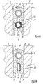
- a such hose is in a joint 6 (Fig. 4), which for example between two masonry sections 7 and is limited by the masonry walls 8, inserted.
- a Joint sealing hose 1 with an annular cross section here preferably compressed laterally so that it is one Has self-retention between the joint walls 8.
- a frictional connection between wall and hose is achieved.
- the hose is held in place. So will For example, a hose 1 with a 20 mm wide fingers Width of 25 mm inserted, which makes it self-sustaining in the Fuge has, but can still be easily inserted.
- a joint sealing hose 1 After such a joint sealing hose 1 is introduced into a joint 6 , it becomes pneumatic or hydraulic, for example pressurized (Fig. 5) This causes the wall thickness due to the compression of the hose body 2 less.
- the circumference of the joint sealing hose preferably changes here 1 not essential.
- a valve device Preferably at the ends the hose 1 a valve device (not shown) for filling the same arranged.
- Another possibility of such a joint sealing hose pressurize and compress the tube body 4 is to achieve reaction plastics in the interior of the hose 2 inject, which react with each other and after the Reaction, for example, an elastic, for example rubber-like Mass result.
- Another way to use the hose to put pressure and the hose body 4 in the area in which it rests on the joint walls 8 is to be compressed, the hose cavity 5 with acrylic resin, polyurethane or the like To fill foams.
- the reaction plastics are under pressure introduced into the hose and / or react under one Volume increase, so that an internal pressure builds up in the hose 1 becomes.
- the tube body with an acrylic gel is preferred pressured that its over a long period of time Maintains viscosity and can be re-pressed at any time.
- Other suitable print media are oils or long-term stable Liquids.
- the internal pressure applied is of the order of 100 bar and can be up to 280 bar.
- FIG. 6 Another possibility according to the invention for sealing a joint 6 consists of a joint sealing hose according to the invention 1 in a joint tape 10 (Fig. 6).
- a joint sealing hose according to the invention has an approximately rectangular shape Cross section on, with two preferably wide, parallel mutually oriented side surfaces 11 and two perpendicular to the side surfaces 11 oriented, preferably narrower than these formed end faces 12.
- In one of the end faces 12 is a deep groove 13 or a in the region of the transverse center Slot 13 introduced parallel to the side walls 11, so that the joint tape 10 thereby has a U-shaped cross section receives.
- the joint sealing hose is in this slot 13 1 inserted.
- a joint sealing hose 1 according to the invention can also can be adapted to wider joints 6.
- This groove or slot 13 extends, for example over three quarters or four fifths of the width of the side surfaces 11.
- a joint tape 10 (Fig. 7) are adjacent to the side surfaces 11 of one Face 12 each have a slot 14, parallel to the side surfaces 11 running into the joint tape 10.
- the slots 14 extend, for example 4/5 of the width of the side surfaces 11 to the opposite End face 12.
- the slots 14 are in the area of Side surfaces 11 narrow tabs 15 are formed. Will in the area a bottom 16 of the slot 14 a section parallel to Side surface 11 and perpendicular to the end face 12, can these tabs 15 either individually or both from the joint tape be cut off. This makes it possible to pre-seal the joint tape to adjust the laying of a joint 6 to the width of the joint 6.
- a joint tape 10 is introduced into a joint 6 such that the closed end face 12 to the outside and the slot 13 provided end face 12 faces inwards. Should be high joint pressures can be sealed, but this can also be reversed respectively.
- the side surfaces 11 lie on the joint 6 which delimits Walls 8 on.
- the joint sealing hose 1 is pneumatic, hydraulically or with pressed reaction plastics pressurized, under which it expands and that Joint tape presses against the walls 8 (Fig. 9, 10).
- FIG. 11 is in the slot 13 of the joint tape 10 to the inside of the joint 6 towards an injection hose 19 in addition to the joint sealing hose 1 introduced.
- the injection hose 19 can for example with an annular cross section (Fig. 11) or with an annular cross section flattened laterally in cross section (Fig. 12).
- Such an injection hose 19 consists of a porous foam, for example perforated hose or a conventional injection hose, through which an injection medium from the hose interior 20 can step outside.
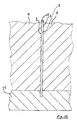
- a joint tape 10 designed in this way is first inserted into the joint, with a joint 6, which is between two masonry 7, the joint for example is elongated in the base plate 21 (FIG. 13), to improve the sealing effect in the floor area.
- the side surface 11 is contoured to a improved hold on uneven or friable masonry guarantee.
- the surface can be toothed, for example be (Fig. 14, 15), the teeth 23 being formed in this way is that flat tooth flanks 24 face the interior of the joint and have steep tooth flanks 25 to the exterior of the joint. At the inside of the joint This will cause pressure on the joint tape a clawing, blocking effect, pushing in of the joint tape, however, not difficult.
- the sealing effect in the process according to the invention can also be obtained only temporarily.
- building up the compression pressure is an option pneumatic or hydraulic way.
- the tube is filled with acrylic gel or reaction plastics, silicone rubbers or foams, especially polyurethane foam, particularly advantageous.
- joint sealing hoses are particularly simple and can be quickly inserted into a joint and by subsequent Filling (pneumatic, hydraulic, with reaction plastics) a tight joint quickly, safely and inexpensively is achieved. Because the hose material in the contact area is compressed to the joint walls, a subsequent Expansion of the joint solely by expanding the Hose material and / or the joint tape are balanced.
- a relatively thick-walled joint sealing hose 1 is preferably used or a joint tape with a joint sealing hose arranged in it 1 with curing reaction plastics under pressure set so that the walls between the reaction plastic and the joint walls 8 are elastically compressed and when the joint 6 is widened, this by expansion the hose body 2 or the joint tape 10 is compensated.
- joint sealing hose 1 with plastics, in particular Reaction plastics filled can be a high pressure in the long run be maintained, which does not require repressing makes.
- a joint tape 10 according to the invention with a joint sealing hose 1 and injection hose 19 is advantageous in that a joint 6 not only can be sealed, but also after sealing can be filled with injection liquid.
- Beneficial at such joint tapes 10 is also that the joint 6th can be sealed securely even with increased internal pressures. For this it is only necessary that the pressure in the compression hose is higher than the pressure that comes from inside the joint 6 acts on the joint tape 10.
- joint sealing hoses and Joint sealing tapes are not limited to masonry joints, it is also possible with these elements, for example pipe sleeves from To seal pipeline connections.
- joint sealing hose according to the invention can do a great deal advantageous in container construction, for sealing pre-pressure pipes or can be used in tunnel construction to seal segments.
Landscapes
- Engineering & Computer Science (AREA)
- Architecture (AREA)
- Physics & Mathematics (AREA)
- Electromagnetism (AREA)
- Civil Engineering (AREA)
- Structural Engineering (AREA)
- Building Environments (AREA)
- Sealing Devices (AREA)
- Gasket Seals (AREA)
Applications Claiming Priority (2)
| Application Number | Priority Date | Filing Date | Title |
|---|---|---|---|
| DE19711897 | 1997-03-21 | ||
| DE1997111897 DE19711897B4 (de) | 1997-03-21 | 1997-03-21 | Vorrichtung zum Dichten von Fugen |
Publications (2)
| Publication Number | Publication Date |
|---|---|
| EP0866190A2 true EP0866190A2 (fr) | 1998-09-23 |
| EP0866190A3 EP0866190A3 (fr) | 1999-06-23 |
Family
ID=7824181
Family Applications (1)
| Application Number | Title | Priority Date | Filing Date |
|---|---|---|---|
| EP98102641A Withdrawn EP0866190A3 (fr) | 1997-03-21 | 1998-02-16 | Procédé et dispositif d'étanchéification de joints |
Country Status (4)
| Country | Link |
|---|---|
| EP (1) | EP0866190A3 (fr) |
| JP (1) | JP3801346B2 (fr) |
| CA (1) | CA2231894C (fr) |
| DE (1) | DE19711897B4 (fr) |
Cited By (8)
| Publication number | Priority date | Publication date | Assignee | Title |
|---|---|---|---|---|
| WO2011020601A1 (fr) * | 2009-08-21 | 2011-02-24 | Pfeifer Holding Gmbh & Co. Kg | Joint pour fermeture étanche d'une cavité de coulée entre au moins deux éléments structuraux |
| DE102012000343A1 (de) * | 2012-01-11 | 2013-07-11 | Manfred Kaleja | Dichtungsvorrichtung, Abdichtverfahren und Verwendung von PU-Schaum |
| DE102020129270A1 (de) | 2020-11-06 | 2022-05-12 | Desoi Gmbh | Verfahren zum Verfüllen von Fugen, Vorrichtung zur Durchführung des Verfahrens und Profilschlauch |
| CN114991222A (zh) * | 2022-05-24 | 2022-09-02 | 中铁隧道勘测设计院有限公司 | 一种用于地铁车站结构减震处置方法 |
| DE102022002665A1 (de) * | 2022-07-21 | 2024-02-01 | Strohmenger OHG | Füllung für Stoßfugen, sowie damit hergestelltes Mauerwerk |
| US12454822B2 (en) * | 2023-04-18 | 2025-10-28 | Ddp Specialty Electronic Materials Us, Llc | Foam envelope for sealing large volumes |
| US12492551B2 (en) * | 2023-04-18 | 2025-12-09 | Dupont Safety & Construction, Inc. | Foam envelope for sealing large volumes |
| US12492550B2 (en) * | 2023-04-18 | 2025-12-09 | Dupont Safety & Construction, Inc. | Foam envelope for sealing large volumes |
Families Citing this family (4)
| Publication number | Priority date | Publication date | Assignee | Title |
|---|---|---|---|---|
| JP3186986U (ja) * | 2013-08-23 | 2013-10-31 | 関電プラント株式会社 | 封止部材 |
| IT201900012477A1 (it) * | 2019-07-22 | 2021-01-22 | Mapei Spa | Procedimento per la sigillatura di giunti fra conci prefabbricati o elementi costruttivi simili, in particolare nella costruzione di tunnel e gallerie, e corrispondenti sistema e striscia di sigillatura |
| KR200493485Y1 (ko) * | 2019-08-27 | 2021-04-07 | 주식회사 서원기술 | 배관용 고무링 |
| KR102226048B1 (ko) * | 2019-10-07 | 2021-03-10 | 주식회사 서원기술 | 배관용 관이음구 어셈블리 |
Family Cites Families (15)
| Publication number | Priority date | Publication date | Assignee | Title |
|---|---|---|---|---|
| FR50665E (fr) * | 1938-07-29 | 1941-02-20 | Joint étanche et son mode d'application | |
| US3222076A (en) * | 1962-04-24 | 1965-12-07 | Woodward Iron Company | Pipe joint packing |
| GB1065922A (en) * | 1964-03-20 | 1967-04-19 | Douglas Harold Perkins | Waterstop gasket |
| US3360273A (en) * | 1965-11-30 | 1967-12-26 | Grace W R & Co | Inflatable gasket for pipe joints |
| BR7603818A (pt) * | 1976-06-14 | 1978-01-03 | P Betti | Elemento de vedacao,para a composicao de juntas,destinado em especial a construcao civil |
| DE3216057A1 (de) * | 1982-04-29 | 1983-11-03 | Siemens AG, 1000 Berlin und 8000 München | Druckausgleichende dichtung, insbesondere fuer kabelgarnituren |
| DE3336357A1 (de) * | 1983-10-06 | 1985-04-18 | Franz Dipl.-Ing. 7900 Ulm Cürten | Kraftschluessige und dichte verbindung von wandelementen mittels druckschlaeuchen |
| DE3427110A1 (de) * | 1984-07-23 | 1986-01-23 | Gleit- Und Lagertechnik Nell Gmbh, 5620 Velbert | Vorrichtung zum abdichten von fugen zwischen zwei bauteilen |
| DE3600375A1 (de) * | 1986-01-09 | 1987-07-16 | Horst Walter Hartwig | Vorrichtung zur abdichtung eines ringraumes |
| EP0267230A1 (fr) * | 1986-03-31 | 1988-05-18 | Bechtel Investments, Inc. | Joint etanche pour beton monte sous pression/compression |
| DE4140616C2 (de) * | 1991-12-10 | 2000-01-13 | Hiendl Heribert | Injektionsschlauch |
| DE4221647C2 (de) * | 1992-07-02 | 1996-04-11 | Webasto Schade Gmbh | Vorrichtung zum Abdichten eines Spaltes |
| JPH08200509A (ja) * | 1995-01-24 | 1996-08-06 | Yokohama Rubber Co Ltd:The | インフレートシール部材 |
| DE29520996U1 (de) * | 1995-03-28 | 1996-07-04 | Heiliger, Christian, 84048 Mainburg | Abdichtungsvorrichtung |
| DE19518732A1 (de) * | 1995-05-22 | 1996-11-28 | Stahl Andreas | Fugenabdichtung |
-
1997
- 1997-03-21 DE DE1997111897 patent/DE19711897B4/de not_active Expired - Fee Related
-
1998
- 1998-02-16 EP EP98102641A patent/EP0866190A3/fr not_active Withdrawn
- 1998-03-12 CA CA 2231894 patent/CA2231894C/fr not_active Expired - Fee Related
- 1998-03-20 JP JP9240898A patent/JP3801346B2/ja not_active Expired - Fee Related
Cited By (9)
| Publication number | Priority date | Publication date | Assignee | Title |
|---|---|---|---|---|
| WO2011020601A1 (fr) * | 2009-08-21 | 2011-02-24 | Pfeifer Holding Gmbh & Co. Kg | Joint pour fermeture étanche d'une cavité de coulée entre au moins deux éléments structuraux |
| DE102012000343A1 (de) * | 2012-01-11 | 2013-07-11 | Manfred Kaleja | Dichtungsvorrichtung, Abdichtverfahren und Verwendung von PU-Schaum |
| DE102020129270A1 (de) | 2020-11-06 | 2022-05-12 | Desoi Gmbh | Verfahren zum Verfüllen von Fugen, Vorrichtung zur Durchführung des Verfahrens und Profilschlauch |
| CN114991222A (zh) * | 2022-05-24 | 2022-09-02 | 中铁隧道勘测设计院有限公司 | 一种用于地铁车站结构减震处置方法 |
| CN114991222B (zh) * | 2022-05-24 | 2024-02-20 | 中铁第六勘察设计院集团有限公司 | 一种用于地铁车站结构减震处置方法 |
| DE102022002665A1 (de) * | 2022-07-21 | 2024-02-01 | Strohmenger OHG | Füllung für Stoßfugen, sowie damit hergestelltes Mauerwerk |
| US12454822B2 (en) * | 2023-04-18 | 2025-10-28 | Ddp Specialty Electronic Materials Us, Llc | Foam envelope for sealing large volumes |
| US12492551B2 (en) * | 2023-04-18 | 2025-12-09 | Dupont Safety & Construction, Inc. | Foam envelope for sealing large volumes |
| US12492550B2 (en) * | 2023-04-18 | 2025-12-09 | Dupont Safety & Construction, Inc. | Foam envelope for sealing large volumes |
Also Published As
| Publication number | Publication date |
|---|---|
| CA2231894A1 (fr) | 1998-09-21 |
| JPH10306876A (ja) | 1998-11-17 |
| JP3801346B2 (ja) | 2006-07-26 |
| EP0866190A3 (fr) | 1999-06-23 |
| CA2231894C (fr) | 2005-06-21 |
| DE19711897A1 (de) | 1998-09-24 |
| DE19711897B4 (de) | 2005-02-24 |
Similar Documents
| Publication | Publication Date | Title |
|---|---|---|
| EP0642620B1 (fr) | Procede pour edifier des murs en beton avec des coffrages precontraints, ecarteur tubulaire et dispositif permettant la mise en oeuvre dudit procede | |
| EP0866190A2 (fr) | Procédé et dispositif d'étanchéification de joints | |
| DE2832614A1 (de) | Verbindungsstueck fuer rohrleitungen | |
| DE69701633T2 (de) | Abdichtung eines spaltes zwischen einer leitung und der dazugehörigenden rohrauskleidung | |
| DE3414180A1 (de) | Dichtungseinrichtung fuer aneinanderstossende, zumindest etwa rohrfoermige bauteile, insbesondere fuer betonformteile | |
| DE2845226C2 (de) | Verfahren zur Herstellung einer Abdichtung um ein Telefonkabel o.dgl. herum sowie Manschette zur Durchführung des Verfahrens | |
| DE68916213T2 (de) | Dichtungen. | |
| DE102017001269A1 (de) | Filterelement und Filteranordnung | |
| DE3532499C1 (de) | Vorrichtung zum hydraulischen Aufweiten von Rohrabschnitten | |
| DE2548979C2 (de) | Verankerung eines Befestigungselementes | |
| DE10043192C1 (de) | Vorrichtung zum Abdichten des Raums zwischen einer in einem Bauelement vorhandenen Durchführung und wenigstens einem die Durchführung durchragenden Gegenstand | |
| AT407063B (de) | Verfahren zum abdichten von spundbohlenkonstruktionen und vorrichtung zur herstellung einer abdichtung in einer klauenkammer einer spundbohle | |
| DE2519517A1 (de) | Verfahren zur abdichtung zwischen den vorgefertigten platten einer im boden angeordneten wand, und vorrichtung zur durchfuehrung des verfahrens | |
| DE3312073C2 (de) | Druckaufbaudorn zum druckdichten Befestigen eines Rohres | |
| DE4305923C2 (de) | Abdichtvorrichtung für Ankerköpfe gegen drückendes Wasser | |
| AT387835B (de) | Rohrdurchfuehrung | |
| DE1811038A1 (de) | Molche zur Verwendung in Rohrleitungen | |
| EP3619447B1 (fr) | Système joint d'étanchéité de bride et procédé de montage | |
| DE29723728U1 (de) | Vorrichtung zum Dichten von Fugen | |
| EP1347122B1 (fr) | Dispositif d'injection sous pression et méthode d'insertion de ce dispositif dans un élément de construction | |
| DE3404354A1 (de) | Verfahren und vorrichtung zum abdichten von rohrleitungen | |
| DE3809885C1 (fr) | ||
| DE8615929U1 (de) | Abdichtung für eine Rohrdurchführung | |
| DE2506140A1 (de) | Querdichtung fuer flachschieber | |
| DE202015106191U1 (de) | Verpressschlauch zum Abdichten von Bauwerksfugen |
Legal Events
| Date | Code | Title | Description |
|---|---|---|---|
| PUAI | Public reference made under article 153(3) epc to a published international application that has entered the european phase |
Free format text: ORIGINAL CODE: 0009012 |
|
| AK | Designated contracting states |
Kind code of ref document: A2 Designated state(s): AT BE CH DE DK ES FI FR GB GR IE IT LI LU NL PT SE |
|
| AX | Request for extension of the european patent |
Free format text: AL;LT;LV;MK;RO;SI |
|
| PUAL | Search report despatched |
Free format text: ORIGINAL CODE: 0009013 |
|
| AK | Designated contracting states |
Kind code of ref document: A3 Designated state(s): AT BE CH DE DK ES FI FR GB GR IE IT LI LU MC NL PT SE |
|
| AX | Request for extension of the european patent |
Free format text: AL;LT;LV;MK;RO;SI |
|
| 17P | Request for examination filed |
Effective date: 19991005 |
|
| K1C3 | Correction of patent application (complete document) published |
Effective date: 19980923 |
|
| AKX | Designation fees paid |
Free format text: AT BE CH DE DK ES FI FR GB GR IE IT LI LU NL PT SE |
|
| 17Q | First examination report despatched |
Effective date: 20000803 |
|
| STAA | Information on the status of an ep patent application or granted ep patent |
Free format text: STATUS: THE APPLICATION IS DEEMED TO BE WITHDRAWN |
|
| 18D | Application deemed to be withdrawn |
Effective date: 20080902 |