EP0866514A1 - Antenne pour la réception de transmission de radio et télévision dans des véhicules - Google Patents
Antenne pour la réception de transmission de radio et télévision dans des véhicules Download PDFInfo
- Publication number
- EP0866514A1 EP0866514A1 EP98104845A EP98104845A EP0866514A1 EP 0866514 A1 EP0866514 A1 EP 0866514A1 EP 98104845 A EP98104845 A EP 98104845A EP 98104845 A EP98104845 A EP 98104845A EP 0866514 A1 EP0866514 A1 EP 0866514A1
- Authority
- EP
- European Patent Office
- Prior art keywords
- antenna
- window
- antennas
- connection point
- phase
- Prior art date
- Legal status (The legal status is an assumption and is not a legal conclusion. Google has not performed a legal analysis and makes no representation as to the accuracy of the status listed.)
- Granted
Links
- 238000011156 evaluation Methods 0.000 claims abstract description 32
- 239000004020 conductor Substances 0.000 claims description 32
- 239000011521 glass Substances 0.000 claims description 21
- 238000010438 heat treatment Methods 0.000 claims description 19
- 230000008878 coupling Effects 0.000 claims description 6
- 238000010168 coupling process Methods 0.000 claims description 6
- 238000005859 coupling reaction Methods 0.000 claims description 6
- 238000013461 design Methods 0.000 claims description 4
- 239000011159 matrix material Substances 0.000 claims description 4
- 230000005284 excitation Effects 0.000 claims 1
- 238000010586 diagram Methods 0.000 description 20
- 238000005457 optimization Methods 0.000 description 10
- 238000000034 method Methods 0.000 description 9
- 230000000694 effects Effects 0.000 description 5
- 238000005259 measurement Methods 0.000 description 5
- 238000005516 engineering process Methods 0.000 description 4
- 230000002349 favourable effect Effects 0.000 description 3
- 230000002123 temporal effect Effects 0.000 description 3
- 230000008901 benefit Effects 0.000 description 2
- 230000005540 biological transmission Effects 0.000 description 2
- 230000006872 improvement Effects 0.000 description 2
- 230000001939 inductive effect Effects 0.000 description 2
- 230000003797 telogen phase Effects 0.000 description 2
- 240000007594 Oryza sativa Species 0.000 description 1
- 235000007164 Oryza sativa Nutrition 0.000 description 1
- 230000009471 action Effects 0.000 description 1
- 230000004913 activation Effects 0.000 description 1
- 230000015572 biosynthetic process Effects 0.000 description 1
- 230000000052 comparative effect Effects 0.000 description 1
- 230000001419 dependent effect Effects 0.000 description 1
- 238000001514 detection method Methods 0.000 description 1
- 230000005672 electromagnetic field Effects 0.000 description 1
- 239000005357 flat glass Substances 0.000 description 1
- 230000010363 phase shift Effects 0.000 description 1
- 230000005855 radiation Effects 0.000 description 1
- 235000009566 rice Nutrition 0.000 description 1
- 230000035945 sensitivity Effects 0.000 description 1
- 230000007480 spreading Effects 0.000 description 1
- 238000012360 testing method Methods 0.000 description 1
- 238000012876 topography Methods 0.000 description 1
Images





Classifications
-
- H—ELECTRICITY
- H01—ELECTRIC ELEMENTS
- H01Q—ANTENNAS, i.e. RADIO AERIALS
- H01Q1/00—Details of, or arrangements associated with, antennas
- H01Q1/12—Supports; Mounting means
- H01Q1/1271—Supports; Mounting means for mounting on windscreens
-
- H—ELECTRICITY
- H01—ELECTRIC ELEMENTS
- H01Q—ANTENNAS, i.e. RADIO AERIALS
- H01Q1/00—Details of, or arrangements associated with, antennas
- H01Q1/12—Supports; Mounting means
- H01Q1/1271—Supports; Mounting means for mounting on windscreens
- H01Q1/1278—Supports; Mounting means for mounting on windscreens in association with heating wires or layers
Definitions
- the invention relates to an antenna in motor vehicles in the meter and decimeter wave range e.g. for radio and television reception. It starts from one Multi-antenna system, e.g. used for the design of an antenna diversity system becomes.
- Such multi-antenna systems are e.g. B. described in EP 0 269 723, DE 36 18 452, DE 39 14 424, Fig. 14, DE 37 19 692, P 36 19 704 and can have different types of antennas, such as rod antennas, windshield antennas or similar use.
- With sufficient RF decoupling of the antennas causes reception interference, which is related with level drops due to the multipath propagation of the electromagnetic Waves occur when the vehicle is positioned differently in the reception area on. This effect is explained by way of example with reference to FIGS. 3 and 4 in EP 0 269 723.
- a scanning antenna diversity system The operation of a scanning antenna diversity system is to occur a reception disturbance in the signal of the connected antenna to switch to another antenna and in a given reception field the number of reception disturbances Make the leading level underruns at the receiver input as small as possible.
- This method is extremely effective, but needs an indicator of the one that is occurring Disturbance and a device for switching the antennas and the antennas themselves. In particular the one with the fault indicator and the switching device in connection with the In some cases, the effort required in the recipient cannot be made. On the other hand it is particularly desirable when using an antenna diversity system, the reception quality to be as big as possible.
- the object of the invention is therefore, with an antenna system according to the preamble of the claim 1 in a vehicle which is in a reception field with statistically incident and superimposed partial waves is moved on usual traffic routes, in the statistical temporal Means without changing the time of the antenna system by switching or adjusting elements to achieve the highest possible reception quality or when using an antenna diversity system during the rest phases - i.e. during the activation time one of the available Receive signals - to improve the reception quality.
- the result of this is that during a trip Statistical curve of the reception level of each of the antennas recorded over time Behavior shows which is practically independent of the form of the relative azimuthal Directional diagram. Due to the different directional diagrams of the individual antennas and because of their different spatial position and different design the reception level drops of the individual antennas appear on the vehicle not congruent over the route and therefore also over time (see Fig. 1b).
- the relationship between the reception quality Q dB and the mean value of the logarithmic signal protection distance (S med / S min ) dB is plotted in FIG. 1c and shows that in areas with a signal quality worth receiving Q dB this increases with an increase of (S med / S min ) dB increases by twice the value of this increase.
- the passive antenna structure with which there is the greatest possible in a receiving area is optimal Value of (S med / S min ) dB results.
- a method for finding an antenna system optimally formed from a plurality of individual antennas is presented on the vehicle.
- the signal quality to be expected for radio reception with an antenna can be determined in comparison to a reference antenna - such as the known rod antenna - from the difference of the mean logarithmic values of the available reception levels (S meddB ) of both antennas from the values for all azimuthal angles of incidence.
- This value can be detected in a particularly effective manner by computer-aided comparative measurements on the antennas mounted on the vehicle, the vehicle being rotated on a rotating stand in defined and sufficiently small angular steps with respect to the direction of incidence of a defined shaft.
- the value S meddB averaged over all azimuthal angle values (eg in dB ⁇ V) of the vehicle rotated around the entire azimuth range of 360 degrees enables the differences in the reception qualities of the vehicle moving on normal traffic routes to be estimated using the curve shown in FIG. 1c.
- an antenna with an optimized S meddB focuses on providing the best possible reception for all users, even if the azimuthal directional diagram is deep , but not too wide indents.
- a measurement run of this type can, however, also be simulated arithmetically by specifying a reception field formed by partial waves incident and overlapping statistically from all azimuthal directions with statistically selected amplitudes.
- the partial waves corresponding to the complex directional characteristics of the individual antennas and the phase and amplitude values of the phase elements and amplitude evaluation elements 12 lead to contributions which are superimposed on amount and phase at the collecting connection point 5 and form the received signal.
- the median value of the reception level can then be mathematically optimized on the basis of a variation of the setting of the phase and amplitude values carried out in the computer.
- the optimization of the median value carried out in this way leads in practice to the same result as the optimization of the median value S meddB from the evaluation of the azimuthal directional diagrams.
- the antenna connection points 4 for the measurement as connection gates considered in terms of the theory of electrical circuits and their complex overall matrix to describe the relationships between the electrical quantities at these Connection gates, to which later the lines 11 and the line and collecting network 9th to be connected with collective connection point 5.
- the optimum phase values and the amplitude evaluation factors of the line and collecting network 9 can be determined in a short computing time with regard to a maximum value of (S med / S min ) dB .
- the phase elements and amplitude evaluation elements 12 can be implemented in the line and collecting network 9 using known circuit technology methods. Examples of this are shown in FIG. 9. Different goals can be pursued for optimization. In the case of narrowband optimization, the median value (S med / S min ) dB will be represented mathematically with respect to a full azimuthal revolution and this value will be optimized by variation calculation. When optimizing a given frequency range (e.g. VHF range), the median value (S med / S min ) dB over all full azimuthal revolutions for all possible reception channels will be represented arithmetically and this value will be optimized by variation calculation.
- a given frequency range e.g. VHF range
- the advantage is achieved that the reception quality is always larger on average than is achieved with one of the individual antennas can be.
- This advantage can be used on the one hand in an antenna system, in which no diversity measures are planned. This is particularly important if no single antenna is available, which has the required reception quality delivers.
- the required reception quality can be achieved.
- the reception quality is also desirable if each of the individual antennas detects the reception quality known high quality antennas. This endeavor is supported by the technology of antenna diversity frequently used in practice is confirmed.
- the present invention can also be used to increase the reception quality Use antenna diversity.
- An arrangement of this type is exemplified in Fig. 6 and elements for switching off signals are identified as switching networks 15.
- the individual antennas using the inventive concept summarized to form an antenna system and for switched Switching networks 15 (diodes) the phase elements and amplitude evaluation elements 12 designed accordingly.
- the phase elements and amplitude evaluation elements 12 designed accordingly.
- this particularly inexpensive embodiment of the invention become in situations in which the reception contributions result in zero and thus Level drops in the overall signal occur, alternating signals of individual antennas switched off, so that they no longer contribute to the overall signal and the level dip in the overall signal disappears.
- the invention delivers even when the invention is applied in diversity techniques the overall signal on average better signal quality because during the Rest phases of the diversity system a better signal quality is achieved, as in the task the invention is required.
- the individual antennas have different azimuthal directional diagrams with the greatest possible azimuthal average gain with low elevation of the incident Have waves and if they are not too close in terms of their radiation centers are such that a sufficient path difference of more than 1/10 of the operating wavelength of waves that excite the antenna.
- a particularly important embodiment of the invention for the application is the attachment several antennas 1 on a window pane.
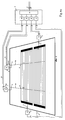
- the formation of such antennas 1 from A heating field on the rear window pane of a car is shown by way of example in FIG. 3.
- wire-shaped electrical ones are laid or printed on the glass pane Heating conductor to form four antennas 1 with the help of conductors across the heating conductors 20 applied.
- the heating conductor between the antennas 1 are the inductive and the resistive effect the heating conductor is represented by inductors and resistors.
- the dashed circle sections qualitatively characterize the regions of the individual that act as capacitive areas Antennas 1.
- the connecting lines 11 are connected to the antenna connection points 4, as shown for an antenna system according to the invention in Fig.4a or in Fig.4b is.
- the via the appropriately dimensioned phase elements and amplitude evaluation elements 12 evaluated received signals at the end of the connecting lines 11 in the line and collecting network 9 combined in the connection point 14 and form the total received signal 10 present at the collective connection point 5 with the improved one Reception quality.
- An antenna arrangement as in Fig. 3, with respect to the gates 4 in their overall behavior is described by scattering parameters, in a similar manner to the antennas 1 in FIG. 2 be designed to an antenna with collective connection point 5.
- the gates 4 via connecting lines, similar to that in FIG. 2, with a line and collecting network 9 are connected, which includes phase elements and amplitude evaluation elements 12.
- amplifier circuits 26 can also be contained in the line and collecting network 9 be. It is essential for the invention that that described in the object of the invention Criterion in the signal at the collective connection point 5 is met.
- the effective relative The spacing of the antennas 1 from one another should, however, be chosen to be large, so that an influence the directional characteristics by combining the antenna signals at the antenna connection point given is.
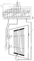
- a layer which has only a limitedly conductive surface 7, represents, can be designed as an antenna system with good properties.
- Such an antenna system is described in Fig. 4a.
- leads 11 to the line and Collecting network 9 the antenna signals via phase elements and amplitude evaluation elements 12 summarized at the connection point 14 and are at the collective connection point 5 available for forwarding to the recipient.
- phase and amplitude values in the links 12 using the optimization method specified above can the reception quality of an antenna system thus formed so far increase that they e.g. is on par with a known rod antenna in the FM range, although the surface resistance of the thin layer is between 5 and 10 ohms.
- the hatched semicircles around the electrodes 2 in Figure 4a qualitatively identify them Electrodes each assigned zones, which are mainly the behavior of the antennas 1 determine with respect to the respective gate 4.
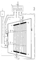
- FIG. 4b Another example of an antenna system according to the invention is a correspondingly designed one Heating field of a rear window pane with parallel printed heating conductors shown in Fig. 4b.
- the gates 4 are each on the edge of the pane by forming connection points 2 realized on the edge of the pane. It is connected to the heating field either via the busbar or via conductors across the heating conductors 20.
- a low-noise line amplifier At the end of each of the connecting lines 11 is a low-noise line amplifier at the input of the line and collecting network 9 26 switched, the output signal of a phase element and amplitude evaluation element 12 is supplied.
- FIGS. 5a and 5b A particularly inexpensive embodiment of the lines 11 in an antenna according to 4a are printed lines as shown in FIGS. 5a and 5b along the edge of the Glass pane 6 are shown.
- 5a shows a coplanar embodiment of the connecting line 11, wherein the conductor located on the edge is preferably used as a ground conductor is.
- the connection point 2 can be designed as a capacitive surface, which on the opposite glass surface is applied and capacitive with the live Head of the connecting line 11 is connected.
- Fig. 5b are the ground conductor 7 and Live conductors 11 on both sides of the glass surface opposite each other.
- connection points 2 of the antennas 1 are by means of Switching networks, which are shown as diodes and controlled by the diversity processor 21 are connected to the line and collecting network 9 via the connecting lines 11.
- the phase elements and amplitude evaluation elements 12 are in one example Embodiment optimized so that all switching networks are permeable 15 a signal is available at the common connection point 5, which signal is the inventive Criteria suffice.
- the overall arrangement acts like an antenna, in which, in the event of a level dip, the signals at the gates 4 in the overall signal largely repeal.
- By successively opening one or more of the switching networks 15 contributions which lead to compensation of the overall signal are removed, so that the level dip disappears.
- the receiver is thus in the position of the diversity processor, in which the diodes 15 are conductive, according to an improved signal offered the invention and in the event of a dip, the latter by the diversity effect canceled.
- each connecting line 11 a line amplifier 26 is used, the output of which allows a multiple of each Phase elements and amplitude evaluation elements 19 to turn on, so that again the connection of the corresponding outputs of the phase elements and amplitude evaluation elements 12 on the antenna selection switch 16 several signals with directional diagrams from high median are available and from the diversity processor 21 for forwarding to Recipients at the collective connection point 5 can be selected.
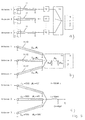
- FIG. 9 shows embodiments of line and collecting networks 9.
- FIG. 9a shows an arrangement according to the invention with connecting lines 11, phase and amplitude evaluation elements 12, a connection point 14, in which the signals for the overall signal at the collecting connection point 5 are combined.
- the phase shifts caused by the connecting lines 11 are naturally to be taken into account.
- the connecting lines 11 and the phase and amplitude evaluation elements 12 are advantageously designed as lines with suitable wave resistances and electrical lengths with a downstream connection point 14 and with impedance matching elements X P1 , X P2 and X S.
- FIG. 9 c) shows the exemplary dimensioning of an arrangement according to FIG. 9 b) for an implemented antenna system with three antennas 1.
- the gate shown at the bottom left in FIG. 10 can also be included in the overall matrix and in the variation calculation and in this way improve the reception in the sense of the invention by connecting it to an optimal impedance - usually a reactance.
- This reactance X is therefore part of the line and collecting network 9 to be optimized, without being contained in this objectively.
- a broadcast receiving antenna according to the invention is three antennas shown without antenna diversity, an antenna amplifier 13, two line amplifiers 26, a line and collecting network 9 to form an inventive Antenna for the FM range as well as an AM amplifier and an AM / FM crossover 22 are housed.
Landscapes
- Details Of Aerials (AREA)
- Radio Transmission System (AREA)
- Two-Way Televisions, Distribution Of Moving Picture Or The Like (AREA)
- Circuits Of Receivers In General (AREA)
Applications Claiming Priority (2)
| Application Number | Priority Date | Filing Date | Title |
|---|---|---|---|
| DE19712197 | 1997-03-22 | ||
| DE19712197 | 1997-03-22 |
Publications (2)
| Publication Number | Publication Date |
|---|---|
| EP0866514A1 true EP0866514A1 (fr) | 1998-09-23 |
| EP0866514B1 EP0866514B1 (fr) | 2001-05-02 |
Family
ID=7824378
Family Applications (1)
| Application Number | Title | Priority Date | Filing Date |
|---|---|---|---|
| EP98104845A Expired - Lifetime EP0866514B1 (fr) | 1997-03-22 | 1998-03-17 | Antenne pour la réception de transmission de radio et télévision dans des véhicules |
Country Status (5)
| Country | Link |
|---|---|
| US (1) | US6236372B1 (fr) |
| EP (1) | EP0866514B1 (fr) |
| CN (1) | CN1195339C (fr) |
| DE (2) | DE19806834A1 (fr) |
| ES (1) | ES2157100T3 (fr) |
Cited By (3)
| Publication number | Priority date | Publication date | Assignee | Title |
|---|---|---|---|---|
| EP1246294A3 (fr) * | 2001-03-26 | 2003-11-05 | FUBA Automotive GmbH & Co. KG | Antenne active réceptrice à large bande |
| EP1225653A3 (fr) * | 2001-01-10 | 2009-11-25 | Delphi Delco Electronics Europe GmbH | Antenne diversitée sur une surface diélectrique dans une carosserié d'automobile |
| EP2457286A4 (fr) * | 2009-07-20 | 2014-07-09 | Telcordia Tech Inc | Système et procédé d'amélioration des performances mimo de communications sans fil sur véhicule |
Families Citing this family (38)
| Publication number | Priority date | Publication date | Assignee | Title |
|---|---|---|---|---|
| DE10010226A1 (de) * | 1999-08-31 | 2001-03-01 | Lindenmeier Heinz | Antenne auf dem Fenster eines Kraftfahrzeugs |
| EP1223637B1 (fr) | 1999-09-20 | 2005-03-30 | Fractus, S.A. | Antennes multiniveau |
| MXPA02004221A (es) | 1999-10-26 | 2003-08-20 | Fractus Sa | Agrupaciones multibanda de antenas entrelazadas. |
| EP1592083B1 (fr) | 2000-01-19 | 2013-04-03 | Fractus, S.A. | antennes miniatures de remplissage d'espace |
| JP2004501543A (ja) * | 2000-04-19 | 2004-01-15 | アドバンスド オートモーティブ アンテナズ ソシエダット デ レスポンサビリダット リミタダ | 改良された自動車用マルチレベルアンテナ |
| US7511675B2 (en) * | 2000-10-26 | 2009-03-31 | Advanced Automotive Antennas, S.L. | Antenna system for a motor vehicle |
| KR20030080217A (ko) | 2001-02-07 | 2003-10-11 | 프레이투스, 에스.에이. | 소형 광대역 고리형 마이크로스트립 패치 안테나 |
| DE20102324U1 (de) | 2001-02-08 | 2001-05-03 | FUBA Automotive GmbH & Co. KG, 31162 Bad Salzdetfurth | Kraftfahrzeugscheibe mit Antennenstrukturen |
| DE60128837T2 (de) * | 2001-04-16 | 2008-02-28 | Fractus, S.A. | Doppelbandige dualpolarisierte gruppenantenne |
| KR100428139B1 (ko) * | 2001-08-28 | 2004-04-30 | 현대자동차주식회사 | 차량용 글라스 안테나 |
| DE10146439C1 (de) | 2001-09-20 | 2002-11-28 | Pilkington Automotive D Gmbh | Fahrzeugantennenscheibe |
| US9755314B2 (en) | 2001-10-16 | 2017-09-05 | Fractus S.A. | Loaded antenna |
| WO2003034545A1 (fr) * | 2001-10-16 | 2003-04-24 | Fractus, S.A. | Antenne a plaque microruban multifrequence avec elements couples non alimentes |
| CN100382385C (zh) | 2001-10-16 | 2008-04-16 | 弗拉克托斯股份有限公司 | 加载天线 |
| EP1436858A1 (fr) * | 2001-10-16 | 2004-07-14 | Fractus, S.A. | Antenne multibande |
| JP2003318623A (ja) * | 2002-02-21 | 2003-11-07 | Toyota Motor Corp | 車両用アンテナ装置 |
| DE10245813A1 (de) * | 2002-10-01 | 2004-04-15 | Lindenmeier, Heinz, Prof. Dr.-Ing. | Aktive Breitbandempfangsantenne mit Empfangspegelregelung |
| JP2004193680A (ja) * | 2002-12-06 | 2004-07-08 | Fujitsu Ten Ltd | 車載用アンテナおよびダイバシティ受信装置 |
| JP2004318466A (ja) * | 2003-04-16 | 2004-11-11 | Matsushita Electric Ind Co Ltd | 商品券、商品券発行システム及び商品券利用システム |
| FR2866156B1 (fr) * | 2004-02-06 | 2006-05-05 | Composants Electr Soc D | Antenne serigraphiee pour lunette arriere et lunette de custode de vehicule automobile de type break. |
| DE102006039357B4 (de) * | 2005-09-12 | 2018-06-28 | Heinz Lindenmeier | Antennendiversityanlage zum Funkempfang für Fahrzeuge |
| US7650173B2 (en) * | 2005-10-06 | 2010-01-19 | Flextronics Ap, Llc | Combined antenna module with single output |
| US8738103B2 (en) | 2006-07-18 | 2014-05-27 | Fractus, S.A. | Multiple-body-configuration multimedia and smartphone multifunction wireless devices |
| DE102007017478A1 (de) * | 2007-04-13 | 2008-10-16 | Lindenmeier, Heinz, Prof. Dr. Ing. | Empfangsanlage mit einer Schaltungsanordnung zur Unterdrückung von Umschaltstörungen bei Antennendiversity |
| EP2037593A3 (fr) * | 2007-07-10 | 2016-10-12 | Delphi Delco Electronics Europe GmbH | Installation de diversité d'antennes pour la réception radio à bande relativement large dans des véhicules |
| DE102007039914A1 (de) * | 2007-08-01 | 2009-02-05 | Lindenmeier, Heinz, Prof. Dr. Ing. | Antennendiversityanlage mit zwei Antennen für den Funkempfang in Fahrzeugen |
| DE102008003532A1 (de) * | 2007-09-06 | 2009-03-12 | Lindenmeier, Heinz, Prof. Dr. Ing. | Antenne für den Satellitenempfang |
| JP5023956B2 (ja) * | 2007-10-15 | 2012-09-12 | 旭硝子株式会社 | 自動車用ガラスアンテナ |
| PT2209221T (pt) * | 2009-01-19 | 2018-12-27 | Fuba Automotive Electronics Gmbh | Sistema de recepção para a soma de sinais de antena em fase |
| DE102009011542A1 (de) * | 2009-03-03 | 2010-09-09 | Heinz Prof. Dr.-Ing. Lindenmeier | Antenne für den Empfang zirkular in einer Drehrichtung der Polarisation ausgestrahlter Satellitenfunksignale |
| DE102009023514A1 (de) * | 2009-05-30 | 2010-12-02 | Heinz Prof. Dr.-Ing. Lindenmeier | Antenne für zirkulare Polarisation mit einer leitenden Grundfläche |
| JP6169586B2 (ja) | 2011-10-28 | 2017-07-26 | コーニング インコーポレイテッド | 赤外線反射能を有するガラス物品および同物品を製造する方法 |
| CN107531562B (zh) | 2015-04-30 | 2021-05-28 | 康宁股份有限公司 | 具有离散的金属银层的导电制品及其制造方法 |
| DE102015211336A1 (de) * | 2015-06-19 | 2016-12-22 | Bayerische Motoren Werke Aktiengesellschaft | Sendeempfänger, Fahrzeug, Verfahren und Computerprogramm für einen Sendeempfänger |
| KR101827706B1 (ko) * | 2016-09-20 | 2018-02-12 | 현대자동차주식회사 | 차량 및 차량의 제어 방법 |
| KR102751890B1 (ko) | 2020-06-26 | 2025-01-09 | 삼성전자주식회사 | 차량에 탑재된 안테나 디바이스 및 안테나 디바이스의 스위칭 방법 |
| US12040537B2 (en) * | 2021-05-19 | 2024-07-16 | Fuba Automotive Electronics Gmbh | Radiation coupled antennas with network |
| CN113472460B (zh) * | 2021-05-26 | 2022-11-01 | 中汽研汽车检验中心(天津)有限公司 | 一种整车级fm天线接收性能测试方法 |
Citations (4)
| Publication number | Priority date | Publication date | Assignee | Title |
|---|---|---|---|---|
| JPS5327348A (en) * | 1976-08-27 | 1978-03-14 | Mitsubishi Electric Corp | Antenna device for diversity reception |
| US4914446A (en) * | 1986-06-02 | 1990-04-03 | Heinz Lindenmeier | Diversity antenna system |
| JPH03220825A (ja) * | 1990-01-25 | 1991-09-30 | Toyota Motor Corp | ダイバシティ受信装置 |
| JPH0613951A (ja) * | 1992-06-26 | 1994-01-21 | Nippon Telegr & Teleph Corp <Ntt> | 移動通信用一周波数交互通信方式におけるダイバーシチ方式 |
Family Cites Families (9)
| Publication number | Priority date | Publication date | Assignee | Title |
|---|---|---|---|---|
| JPS57188102A (en) * | 1981-05-15 | 1982-11-19 | Asahi Glass Co Ltd | Glass antenna for automobile |
| JPS57188103A (en) * | 1981-05-15 | 1982-11-19 | Asahi Glass Co Ltd | Antenna for radio receiver of automobile |
| DE3410415A1 (de) * | 1984-03-21 | 1985-09-26 | Gerhard Prof. Dr.-Ing. 8012 Ottobrunn Flachenecker | Aktive antenne in der heckscheibe eines kraftfahrzeugs |
| US4823140A (en) * | 1984-06-18 | 1989-04-18 | Asahi Glass Company Ltd. | Antenna device for a television receiver mounted on an automobile |
| DE3619704A1 (de) | 1986-06-12 | 1987-12-17 | Lindenmeier Heinz | Antennenanordnung fuer diversityempfang in der fensterscheibe eines kraftfahrzeugs |
| DE3719692A1 (de) | 1987-06-12 | 1988-12-22 | Flachenecker Gerhard | Mehrantennenanordnung fuer antennendiversity in einer fensterscheibe |
| KR890001219A (ko) * | 1987-06-27 | 1989-03-18 | 노브오 사수가 | 자동차용 수신장치 |
| DE3914424A1 (de) | 1989-05-01 | 1990-12-13 | Lindenmeier Heinz | Antenne mit vertikaler struktur zur ausbildung einer ausgedehnten flaechenhaften kapazitaet |
| DE69326271T2 (de) * | 1992-03-27 | 1999-12-30 | Asahi Glass Co. Ltd., Tokio/Tokyo | Diversity-Fensterantenne für Kraftfahrzeug |
-
1998
- 1998-02-18 DE DE19806834A patent/DE19806834A1/de not_active Withdrawn
- 1998-03-17 DE DE59800657T patent/DE59800657D1/de not_active Expired - Lifetime
- 1998-03-17 EP EP98104845A patent/EP0866514B1/fr not_active Expired - Lifetime
- 1998-03-17 ES ES98104845T patent/ES2157100T3/es not_active Expired - Lifetime
- 1998-03-20 CN CNB981058159A patent/CN1195339C/zh not_active Expired - Lifetime
- 1998-03-23 US US09/046,226 patent/US6236372B1/en not_active Expired - Lifetime
Patent Citations (4)
| Publication number | Priority date | Publication date | Assignee | Title |
|---|---|---|---|---|
| JPS5327348A (en) * | 1976-08-27 | 1978-03-14 | Mitsubishi Electric Corp | Antenna device for diversity reception |
| US4914446A (en) * | 1986-06-02 | 1990-04-03 | Heinz Lindenmeier | Diversity antenna system |
| JPH03220825A (ja) * | 1990-01-25 | 1991-09-30 | Toyota Motor Corp | ダイバシティ受信装置 |
| JPH0613951A (ja) * | 1992-06-26 | 1994-01-21 | Nippon Telegr & Teleph Corp <Ntt> | 移動通信用一周波数交互通信方式におけるダイバーシチ方式 |
Non-Patent Citations (3)
| Title |
|---|
| PATENT ABSTRACTS OF JAPAN vol. 002, no. 062 (E - 032) 11 May 1978 (1978-05-11) * |
| PATENT ABSTRACTS OF JAPAN vol. 015, no. 506 (E - 1148) 20 December 1991 (1991-12-20) * |
| PATENT ABSTRACTS OF JAPAN vol. 018, no. 213 (E - 1538) 15 April 1994 (1994-04-15) * |
Cited By (3)
| Publication number | Priority date | Publication date | Assignee | Title |
|---|---|---|---|---|
| EP1225653A3 (fr) * | 2001-01-10 | 2009-11-25 | Delphi Delco Electronics Europe GmbH | Antenne diversitée sur une surface diélectrique dans une carosserié d'automobile |
| EP1246294A3 (fr) * | 2001-03-26 | 2003-11-05 | FUBA Automotive GmbH & Co. KG | Antenne active réceptrice à large bande |
| EP2457286A4 (fr) * | 2009-07-20 | 2014-07-09 | Telcordia Tech Inc | Système et procédé d'amélioration des performances mimo de communications sans fil sur véhicule |
Also Published As
| Publication number | Publication date |
|---|---|
| DE59800657D1 (de) | 2001-06-07 |
| ES2157100T3 (es) | 2001-08-01 |
| EP0866514B1 (fr) | 2001-05-02 |
| US6236372B1 (en) | 2001-05-22 |
| CN1195339C (zh) | 2005-03-30 |
| DE19806834A1 (de) | 1998-09-24 |
| CN1195904A (zh) | 1998-10-14 |
Similar Documents
| Publication | Publication Date | Title |
|---|---|---|
| EP0866514B1 (fr) | Antenne pour la réception de transmission de radio et télévision dans des véhicules | |
| EP1076375B1 (fr) | Antenne en diversité pour un système de diversité dans un véhicule | |
| EP0269723B1 (fr) | Systeme d'antennes de reception en diversite | |
| DE69326271T2 (de) | Diversity-Fensterantenne für Kraftfahrzeug | |
| EP0346591B1 (fr) | Antenne pour la réception des ondes métriques installée ensemble avec un chauffage de pare-brise de véhicule. | |
| DE2914791C2 (fr) | ||
| DE102006039357B4 (de) | Antennendiversityanlage zum Funkempfang für Fahrzeuge | |
| EP0155647B1 (fr) | Arrangement d'antenne dans la vitre arrière d'une voiture | |
| EP1968156B1 (fr) | Antenne pour la réception radio dotée d'une fonction de diversité dans un véhicule | |
| DE4318869C2 (de) | Funkantennen-Anordnung auf der Fensterscheibe eines Kraftfahrzeugs und Verfahren zur Ermittlung ihrer Beschaltung | |
| EP1246294B1 (fr) | Antenne active réceptrice d'un vehicule à large bande | |
| EP1406349B1 (fr) | Antenne active de réception large bande avec régulation du niveau de réception | |
| EP3547561B1 (fr) | Agencement d'antenne pour la communication bidirectionnelle de véhicules | |
| EP0297328B1 (fr) | Arrangement de plusieurs antennes de vitres pour obtenir diversité d'antennes | |
| DE19533105A1 (de) | Hochempfindliche, ungerichtete Schleifenantennenanordnung, die geeignet ist für eine Verwendung in einem Kraftfahrzeug | |
| EP1341260A1 (fr) | Dispositif d'antennes servant à la réception des signaux satellites et/ou terrestres sur un véhicule | |
| WO1996031918A1 (fr) | Antenne montee sur fenetre, a coefficient eleve d'attenuation de la transmission de chaleur | |
| DE102013203789A1 (de) | Antennenanordnung mit veränderlicher Richtcharakteristik | |
| DE69522200T2 (de) | Antennenanordnung auf der Kraftfahrzeugscheibe | |
| DE1945850A1 (de) | Richtantenne | |
| DE10314094A1 (de) | Antennenscheibe | |
| DE4323239C2 (de) | Antennenstruktur für eine Kraftfahrzeug-Heckscheibe | |
| DE3619704C2 (fr) | ||
| DE4423191A1 (de) | Fensterscheibenantenne mit extremer Bandbreite für Kraftfahrzeuge | |
| DE19527304C1 (de) | Für den Empfang von Radiowellen im UKW-Bereich eingerichtete Kraftfahrzeugscheibe |
Legal Events
| Date | Code | Title | Description |
|---|---|---|---|
| PUAI | Public reference made under article 153(3) epc to a published international application that has entered the european phase |
Free format text: ORIGINAL CODE: 0009012 |
|
| AK | Designated contracting states |
Kind code of ref document: A1 Designated state(s): DE ES FR GB IT SE |
|
| AX | Request for extension of the european patent |
Free format text: AL;LT;LV;MK;RO;SI |
|
| 17P | Request for examination filed |
Effective date: 19981009 |
|
| 17Q | First examination report despatched |
Effective date: 19981118 |
|
| AKX | Designation fees paid |
Free format text: DE ES FR GB IT SE |
|
| RBV | Designated contracting states (corrected) |
Designated state(s): DE ES FR GB IT SE |
|
| RAP1 | Party data changed (applicant data changed or rights of an application transferred) |
Owner name: FUBA AUTOMOTIVE GMBH & CO. KG |
|
| GRAG | Despatch of communication of intention to grant |
Free format text: ORIGINAL CODE: EPIDOS AGRA |
|
| GRAG | Despatch of communication of intention to grant |
Free format text: ORIGINAL CODE: EPIDOS AGRA |
|
| GRAH | Despatch of communication of intention to grant a patent |
Free format text: ORIGINAL CODE: EPIDOS IGRA |
|
| GRAH | Despatch of communication of intention to grant a patent |
Free format text: ORIGINAL CODE: EPIDOS IGRA |
|
| GRAA | (expected) grant |
Free format text: ORIGINAL CODE: 0009210 |
|
| AK | Designated contracting states |
Kind code of ref document: B1 Designated state(s): DE ES FR GB IT SE |
|
| REF | Corresponds to: |
Ref document number: 59800657 Country of ref document: DE Date of ref document: 20010607 |
|
| ET | Fr: translation filed | ||
| ITF | It: translation for a ep patent filed | ||
| REG | Reference to a national code |
Ref country code: ES Ref legal event code: FG2A Ref document number: 2157100 Country of ref document: ES Kind code of ref document: T3 |
|
| GBT | Gb: translation of ep patent filed (gb section 77(6)(a)/1977) |
Effective date: 20010806 |
|
| REG | Reference to a national code |
Ref country code: GB Ref legal event code: IF02 |
|
| PLBE | No opposition filed within time limit |
Free format text: ORIGINAL CODE: 0009261 |
|
| STAA | Information on the status of an ep patent application or granted ep patent |
Free format text: STATUS: NO OPPOSITION FILED WITHIN TIME LIMIT |
|
| 26N | No opposition filed | ||
| PGFP | Annual fee paid to national office [announced via postgrant information from national office to epo] |
Ref country code: SE Payment date: 20040304 Year of fee payment: 7 |
|
| PGFP | Annual fee paid to national office [announced via postgrant information from national office to epo] |
Ref country code: GB Payment date: 20040317 Year of fee payment: 7 |
|
| PGFP | Annual fee paid to national office [announced via postgrant information from national office to epo] |
Ref country code: ES Payment date: 20040318 Year of fee payment: 7 |
|
| PG25 | Lapsed in a contracting state [announced via postgrant information from national office to epo] |
Ref country code: GB Free format text: LAPSE BECAUSE OF NON-PAYMENT OF DUE FEES Effective date: 20050317 |
|
| PG25 | Lapsed in a contracting state [announced via postgrant information from national office to epo] |
Ref country code: SE Free format text: LAPSE BECAUSE OF NON-PAYMENT OF DUE FEES Effective date: 20050318 Ref country code: ES Free format text: LAPSE BECAUSE OF NON-PAYMENT OF DUE FEES Effective date: 20050318 |
|
| EUG | Se: european patent has lapsed | ||
| GBPC | Gb: european patent ceased through non-payment of renewal fee |
Effective date: 20050317 |
|
| REG | Reference to a national code |
Ref country code: ES Ref legal event code: FD2A Effective date: 20050318 |
|
| REG | Reference to a national code |
Ref country code: FR Ref legal event code: TP |
|
| REG | Reference to a national code |
Ref country code: FR Ref legal event code: PLFP Year of fee payment: 18 |
|
| PGFP | Annual fee paid to national office [announced via postgrant information from national office to epo] |
Ref country code: IT Payment date: 20150324 Year of fee payment: 18 Ref country code: DE Payment date: 20150327 Year of fee payment: 18 |
|
| PGFP | Annual fee paid to national office [announced via postgrant information from national office to epo] |
Ref country code: FR Payment date: 20150317 Year of fee payment: 18 |
|
| REG | Reference to a national code |
Ref country code: DE Ref legal event code: R119 Ref document number: 59800657 Country of ref document: DE |
|
| REG | Reference to a national code |
Ref country code: FR Ref legal event code: ST Effective date: 20161130 |
|
| PG25 | Lapsed in a contracting state [announced via postgrant information from national office to epo] |
Ref country code: FR Free format text: LAPSE BECAUSE OF NON-PAYMENT OF DUE FEES Effective date: 20160331 Ref country code: DE Free format text: LAPSE BECAUSE OF NON-PAYMENT OF DUE FEES Effective date: 20161001 |
|
| PG25 | Lapsed in a contracting state [announced via postgrant information from national office to epo] |
Ref country code: IT Free format text: LAPSE BECAUSE OF NON-PAYMENT OF DUE FEES Effective date: 20160317 |