EP0866631A2 - Dispositif de terminaison de plusieurs lignes et son procédé "OAM" - Google Patents
Dispositif de terminaison de plusieurs lignes et son procédé "OAM" Download PDFInfo
- Publication number
- EP0866631A2 EP0866631A2 EP97115101A EP97115101A EP0866631A2 EP 0866631 A2 EP0866631 A2 EP 0866631A2 EP 97115101 A EP97115101 A EP 97115101A EP 97115101 A EP97115101 A EP 97115101A EP 0866631 A2 EP0866631 A2 EP 0866631A2
- Authority
- EP
- European Patent Office
- Prior art keywords
- cell
- line
- oam
- identifier
- connection
- Prior art date
- Legal status (The legal status is an assumption and is not a legal conclusion. Google has not performed a legal analysis and makes no representation as to the accuracy of the status listed.)
- Withdrawn
Links
Images


Classifications
-
- H—ELECTRICITY
- H04—ELECTRIC COMMUNICATION TECHNIQUE
- H04Q—SELECTING
- H04Q11/00—Selecting arrangements for multiplex systems
- H04Q11/04—Selecting arrangements for multiplex systems for time-division multiplexing
- H04Q11/0428—Integrated services digital network, i.e. systems for transmission of different types of digitised signals, e.g. speech, data, telecentral, television signals
- H04Q11/0478—Provisions for broadband connections
-
- H—ELECTRICITY
- H04—ELECTRIC COMMUNICATION TECHNIQUE
- H04L—TRANSMISSION OF DIGITAL INFORMATION, e.g. TELEGRAPHIC COMMUNICATION
- H04L12/00—Data switching networks
- H04L12/54—Store-and-forward switching systems
- H04L12/56—Packet switching systems
- H04L12/5601—Transfer mode dependent, e.g. ATM
- H04L2012/5625—Operations, administration and maintenance [OAM]
-
- H—ELECTRICITY
- H04—ELECTRIC COMMUNICATION TECHNIQUE
- H04L—TRANSMISSION OF DIGITAL INFORMATION, e.g. TELEGRAPHIC COMMUNICATION
- H04L12/00—Data switching networks
- H04L12/54—Store-and-forward switching systems
- H04L12/56—Packet switching systems
- H04L12/5601—Transfer mode dependent, e.g. ATM
- H04L2012/5628—Testing
Definitions
- This invention relates to a plural-line terminating apparatus and a method of OAM processing in this apparatus. More particularly, the invention relates to a plural-line terminating apparatus for accommodating a plurality of lines, converting signals from these plurality of lines to ATM cells and sending the ATM cells to an ATM switch, sending ATM cells from the switch upon converting the cells to line signals, and executing OAM processing of a plurality of lines. The invention further relates to a method of executing this OAM processing.
- Asynchronous Transfer Mode which is the core of a broadband ISDN, makes it possible to divide a variety of information such as voice, video and data into fixed-length packets, referred to as cells, and to transfer the information over a network at high speed while handling the information in a consolidated manner.
- Monitoring network failures in the operation of an ATM network is important, and use is made of OAM (Operation, Administration and Maintenance) Fault Management cells (AIS cells, RDI cells, etc.) to monitor connection failure.
- OAM Operaation, Administration and Maintenance
- Fault Management cells AIS cells, RDI cells, etc.
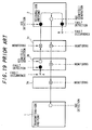
- Fig. 19 is a diagram for describing the basic mechanism of OAM (Operation, Administration and Maintenance) flow. Shown in Fig. 19 are an end point 1 on a transmitting side, an end point 2 on a receiving side, and connecting points 3a, 3b, 3c ⁇ at which OAM cells can be extracted/inserted. If a defect A has been sensed at a certain connecting point 3b, an AIS (Alarm Indication Signal) cell is sent in the downstream direction in order to notify the downstream side of the connection of the defect A. Upon receiving the AIS cell or directly detecting a defect B, the end point 2 downstream of the connection sends back an RDI (Remote Defect Indication) cell to the opposing end point on the upstream side.
- AIS Alarm Indication Signal
- the end point 1 upstream of the connection is capable of managing defects on the transmitting and receiving sides in both directions, and the connecting points 3a ⁇ 3c are capable of discriminating the occurrence of defects and the locations thereof by monitoring the AIS and RDI cells.
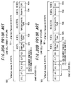
- Figs. 20A and 20B are formats of OAM cells, in which Fig. 20A shows the format (F4 OAM flow) of an OAM cell for a VP connection and Fig. 20B the format (F5 OAM flow) of an OAM cell for a VC connection.
- the F4 OAM flow implements (1) discrimination and notification of faults in a VP connection (a VP-connection fault management function), and (2) notification of error rate, cell loss rate and cell mixing rate of user information cells (a VP-connection performance management function).
- the F5 OAM flow implements a VC-connection fault management function and a VC-connection performance management function in a manner similar to that of the F4 flow.
- the ATM cell payload 101 is composed of the following information:
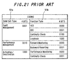
- Fig. 21 is a correspondence table of OAM cell type 101a vs. function type 101b. The following are advised as the OAM cell types:
- a segment OAM cell is a cell inserted/extracted in a segment and is valid only in a segment interval; it is not transmitted outside of a segment interval.
- An end-to-end OAM cell is a cell valid end to end of a set connection; it is discarded at the end point of a connection.
- the connection point undergoes a transition to an alarm state at reception of the AIS cell.
- Restoration to the normal state is made in response to non-reception of the AIS cell for 2.5 ⁇ 0.5 seconds or reception of a user cell (alarm-status recovery cell).
- the function-specific field 101c of the Fault Management cell indicates the details of a fault (fault category and location, etc.), as mentioned above, at the time of a failure the maintenance personnel may operate the network by referring to the detailed information that has been recorded in the function-specific field 101c of the Fault Management cell.
- Fig. 22 is a block diagram illustrating the configuration of an ATM switching system. Shown in Fig. 22 are subscriber interfaces (or line IFs) 11 11 ⁇ 11 1N , 11 21 ⁇ 11 2n , 11 31 ⁇ 11 3n , 11 41 ⁇ 11 4n connected to corresponding lines (transmission lines), multiplexer/demultiplexers 12 1 ⁇ 12 4 , an ATM switch unit 13, a system controller 14 and a maintenance terminal 15.
- the ATM switch unit 13 is connected to the plurality of multiplexer/demultiplexers 12 1 - 12 4 , switches input cells from certain multiplexer/demultiplexers and outputs the cells to prescribed multiplexer/demultiplexers.
- the multiplexer/demultiplexers 12 1 ⁇ 12 4 which are connected to the pluralities of line interfaces 11 11 ⁇ 11 1n , 11 21 ⁇ 11 2n , 11 31 ⁇ 11 3n , 11 41 ⁇ 11 4n , respectively, multiplex incoming cells from a plurality of line interfaces IF and output the cells to the ATM switch unit 13. Furthermore, the multiplexer/demultiplexers 12 1 ⁇ 12 4 demultiplex and output incoming cells, which arrive from the ATM switch unit 13, to the pertinent line interfaces.
- the line interfaces 11 11 ⁇ 11 4n which are connected to the corresponding multiplexer/demultiplexers 12 1 ⁇ 12 4 , each extract an ATM cell from the payload of a frame signal of a prescribed format (e.g. a SONET frame) that has entered from the line, convert the cell to one having the cell format within the switch and output the cell to the multiplexer/demultiplexer.
- the cell format within the switch is provided with information TAG for routing purposes.
- the ATM switch unit switches a cell to a prescribed path by referring to this tag information TAG.
- the line interfaces 11 11 ⁇ 11 4n convert the cells of the switch cell format that enter from the multiplexer/demultiplexers 12 1 ⁇ 12 4 to cells having the ATM cell format, map each ATM cell to the payload of the SONET frame and send the ATM cell to the line side.
- the system controller 14 controls the line interfaces 11 11 ⁇ 11 4n , multiplexer/demultiplexers 12 1 ⁇ 12 4 and ATM switch unit 13.
- Fig. 23 is a block diagram showing the construction of a line interface.
- One line interface 11 is provided in correspondence with one set of outgoing/incoming lines and has a one-line/one-package construction in which one line interface 11 is formed in one package.
- the multiplexer/demultiplexer (MUX/DMUX) and ATM switch are shown at 12 and 13, respectively.
- the line interface 11 includes a physical terminator 21 for forming a frame signal having a prescribed format that has entered from the outgoing line into a cell stream and outputting the cell stream to the side of the ATM switch, and for forming a cell stream, which has entered from the side of the ATM switch, into a frame signal having the above-mentioned format and sending the frame signal to the corresponding line.
- a UPC (Usage Parameter Control) processor 22 performs monitoring to determine whether the reported value of transmission capacity and the actual cell inflow quantity conform. When cells in excess of the reported value flow in, processing for discarding cells in contravention of the stipulation is executed.
- the line interface 11 further includes a billing/NDC processor 23, which performs billing control and NDC control for counting the number of passing cells and creating billing data, and an OAM processor 24.
- the physical terminator 21 has an optoelectric converter for converting a light signal to an electric signal, an electro-optic converter for converting an electric signal to a light signal, and a SONET terminator.
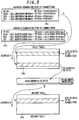
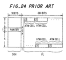
- the SONET terminator deletes overhead (section overhead SOH and path overhead POH) from a frame signal having a SONET STC-3C (156 Mbps) format shown for example in Fig. 24, extracts ATM cells from the payload field PL and then converts the format to the cell format within the switch and outputs the cells. Further, the physical terminator 21 sends a cell stream, which has entered from the switch side, to the line upon converting the cell stream to a frame having the SONET STS-3C format shown in Fig. 24.
- the conventional line interface has the one-line/one-package architecture. Consequently, the OAM processor 24 constituting the line interface 11 is so adapted that it executes OAM processing without being aware of the identification of the line. In other words, the OAM processor 24 executes OAM processing without being aware of the particular line via which a cell has entered and without being aware of the particular line to which a cell is output.
- NVP connection network VP connection
- line management processing is executed by sending and receiving OAM cells for the NVP connection between the adjacent ATM switches.
- OAM cell for the NVP connection is terminated by the OAM processor of the first of the adjacent ATM switches and is not sent downstream. Therefore, in a case where the OAM cell for the NVP connection notifies of a line failure, a problem which arises is that the line failure will not be communicated to ATM switches other than these ATM switches, namely to ATM switches located downstream.
- an object of the present invention is to arrange it so that a plurality of lines can be controlled commonly by a single OAM processor, an increase in amount of hardware can be suppressed by reducing the capacity of a management table and OAM processing that takes lines into account can be executed efficiently.
- Another object of the present invention is to so arrange it that the band will not be exceeded at each of the lines owing to insertion of OAM cells.
- Another object of the present invention is to so arrange it that line failure of which notification has been given by an OAM cell for an NVP connection can be communicated also to ATM switches other than ATM switches for the NVP connection.
- a further object of the present invention is to make it possible to reduce the capacity of management tables and suppress an increase in amount of hardware even in a case where OAM processing is executed separately for NVP connections and ordinary VP/VC connections.
- a plural-line terminating apparatus for accommodating a plurality of lines, converting signals from these plurality of lines to cells, sending the cells to a switch, sending cells from the switch to lines upon converting the cells to line signals, and executing OAM processing of the plurality of lines, comprising (1) a first signal converter for converting a transmission line signal, which enters from each line, to cells, subsequently multiplexing the cells onto a cell stream, and adding a line identifier, which specifies the line on which the cell arrived, onto a cell header of the cell, (2) a header converter for converting a combined identifier, which is a combination of the line identifier and connection identification (VPI/VCI) added onto a cell, to an internal-processing identifier, and sending the cell having the internal-processing identifier to the switch side, (3) a header back-converter for converting the internal-processing identifier of each cell in a cell stream that has entered from the switch
- a plurality of lines can be controlled commonly by a single OAM processor.
- the capacity of the management table can be reduced and an increase in hardware can be suppressed.
- the first signal converter is provided with means for generating, on a per-line basis, a empty cell in a period in which a valid cell is absent, adding a line identifier onto the empty cell and inserting the empty cell into the cell stream
- the OAM processor is provided with means which, when an OAM cell is sent to a prescribed line by OAM processing, is for discriminating an empty cell having the line identifier of this line from the cell stream, and inserting the above-mentioned OAM cell at the position of this empty cell.
- the first signal converter is provided with means for adding an identifier onto a header of an empty cell generated by removing an overhead field of a line signal that enters from a line
- the OAM processor is provided with means for inhibiting insertion of an OAM cell at the position of the empty cell having this identifier.
- a line terminating apparatus comprising (1) first and second management tables for storing data necessary for OAM processing of an ordinary VP/VC connection and for OAM processing of an NVP connection, respectively, (2) means for converting a line-identifier/VPI/VCI to an internal-processing identifier in case of a VP/VC connection cell and converting a line-identifier/VPI to a degenerate VPI in case of an OAM cell for an NVP connection, and (3) means for executing OAM processing of the VP/VC connection and NVP connection using data read from the first and second management tables based upon the internal-processing identifier and degenerate VPI obtained by the conversion.
- the capacities of the management tables can be reduced by using the degenerate VPI and internal-processing identifier and an increase in the amount of hardware can be suppressed.
- the second management table which is addressed by the degenerate VPI, is provided with an area for storing occurrence of a fault in a line corresponding to this degenerate VPI
- the first management table which is addressed by the internal-processing identifier, is provided with an area for holding the degenerate VPI.
- the OAM processor thereafter scans the first management table to read degenerate VPIs that correspond to each of the internal-processing identifiers, determines whether occurrence of a fault has been recorded in fault-status indication areas of the second management table designated by the degenerate VPIs, and, if occurrence of a fault has been recorded, sends downstream a VC-connection OAM cell that is for giving notification of the occurrence of the fault. If this arrangement is adopted, ATM switches other than the ATM switches of NVP connections can be notified of a line defect of which notification has been given by an OAM cell for an NVP connection.
- Fig. 1 is a diagram showing the construction of a plural-line interface according to a first embodiment of the present invention.
- a single package accommodates plural sets of incoming/outgoing lines.
- Shown in Fig. 1 are a physical layer terminating unit 30 having a physical layer terminator 31 on the input side to which a plurality of incoming lines (IN lines #0 ⁇ #n) are connected and a physical layer terminator 32 on the output side to which a plurality of outgoing lines (OUT lines #0 ⁇ #n) are connected.
- An ATM layer terminating unit 33 is provided between the physical layer terminating unit 30 and a multiplexer/demultiplexer, which is not shown.
- the ATM layer terminating unit 33 includes a header converter 34 for converting a line-identifier/VPI/VCI, which has been added onto a cell, to an identifier ICID for internal processing purposes, a UPC processor 35, a billing/NDC processor 36, an OAM processor 37 and a header back-converter 38 for converting the internal-processing identifier ICID back to the line-identifier/VPI/VCI.
- the physical terminators 31, 32 on the input and output sides have the constructions shown in Fig. 2.
- (1) one line is connected if the line has an OC12C (624 Mbps) format)
- (2) a maximum of four lines are connected if the lines have an OC3C (156 Mbps) format
- (3) a maximum of 12 lines are connected if the lines have a DS3 format.
- the physical layer terminator 31 on the input side has format converters 31a 0 ⁇ 31a n for converting the format of signals that enter from the lines #0 ⁇ #n to the ATM cell format (Fig. 3) prevailing within the switch, and for outputting the resulting cells.
- the format converters 31a 0 ⁇ 31a n further output a frame pulse and an enable signal CEB, which indicates whether the cell is valid or invalid, together with the cell CL.
- the physical terminator 31 further includes a multiplexer 31b for time-division multiplexing and outputting ATM cells that enter from each of the format converters 31a 0 ⁇ 31a n .
- the format converters 31a 0 ⁇ 31a n remove overhead (section overhead SOH and path overhead POH) from the signals, extract the ATM cells from the payloads PL, make the conversion to the cell format prevailing within the switch and then output the resulting cells.
- Fig. 3 is a diagram useful in describing an ATM cell output by the format converters 31a 0 ⁇ 31a n .
- HD represents a 6-octet header and PL a 48-octet payload.
- the header HD includes a VP-connection/VC-connection identifier VP, a forced empty-cell identifier E, a line identification tag TAGD (0 ⁇ 9), a virtual-path-identifier/virtual-channel-identifier VPI/VCI, payload type identifier PTI and cell loss priority CLP.
- the VP-connection/VC-connection identifier VP specifies whether a cell is a VP-connection cell or a VC-connection cell. If the VPI that has been added onto a cell agrees with a predetermined value, VP is made "1" to indicate a VP-connection cell; otherwise, VP is made "0" to indicate a VC-connection cell.
- the tag TAGD (0 ⁇ 9) is a line identifier for identifying the line on which the cell arrived.
- the 12 lines of the DS3 format are represented by four bits and the four lines of the OC3C (156 Mbps) format are represented by two bits.
- the physical layer terminator 32 on the output side has a demultiplexer 32a for demultiplexing a cell stream, which has entered from the switch side, onto each of the lines based upon the tags (line identifiers) that have been added onto the cells, and format converters 32b 0 ⁇ 32b n for converting the ATM cells, which have the format shown in Fig. 3, to transmission line signals and sending the signals to the lines.
- a demultiplexer 32a for demultiplexing a cell stream, which has entered from the switch side, onto each of the lines based upon the tags (line identifiers) that have been added onto the cells
- format converters 32b 0 ⁇ 32b n for converting the ATM cells, which have the format shown in Fig. 3, to transmission line signals and sending the signals to the lines.
- the header converter 34 converts a combined identifier, which is a combination of the line identifier and VPI/VCI value that have been added onto a cell, to an internal-processing identifier, to the internal-processing identifier ICID having a small number of bits.
- the sizes of the various management tables can be reduced by making the conversion to ICID having the small number of bits.
- Fig. 5 is a diagram useful in describing the method of making the conversion to ICID. Shown in Fig. 5 are a first table 34a for storing a base address BA necessary to obtain the ICID of a VP connection and the ICID of a VC connection, a second table 34b for storing the ICID of a VC connection, and address generators 34c, 34d.
- the address generator 34c refers to the line identifier to determine the line on which the cell arrived and generates an address A in accordance with (1) ⁇ (3) below. Specifically, the address generator 34c
- the 12-bit internal-processing identifier ICID of the VP connection is subsequently obtained from the storage area of the first table 34a designated by the address A.
- the address generator 34d refers to the line identifier to determine the line on which the cell arrived and generates an address A in accordance with (1) ⁇ (3) below. Specifically, the address generator 34d
- the 12-bit base address BA is obtained from the storage area of the first table 34a designated by the address A. Thereafter, a 20-bit address B is generated by combining the 12-bit base address BA and 8 lower order bits of the VCI. If stored data is read out of the storage area of the second table 34b designated by the address B, the 12-bit internal-processing identifier ICID of the VC connection is obtained.
- the line-identifier/VPI/VCI (a total of 38 bits) is converted to the 12-bit internal-processing identifier ICID, which is added on at the VPI position, as shown in Fig. 6. Thereafter, data necessary for OAM processing of each line is managed unitarily in the connection management table using the internal-processing identifier ICID.
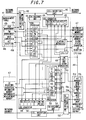
- Fig. 7 is block diagram showing the overall configuration of the OAM processor 37. Shown in Fig. 7 are an incoming management table 41 and an outgoing management table 51.
- the management tables 41, 51 respectively include (1) connection management tables 41a, 51a addressed by ICID, (2) PM management tables 41b, 51b addressed by a PM-ID (Performance Management Identifier), (3) back-conversion tables 41c, 51c and (4) Act reception tables 41d, 51d.
- Numerals 42, 52 denote incoming/outgoing cell discrimination units.
- Cell processors 43, 53 execute processing conforming to identified incoming/outgoing OAM and user cells.
- Numerals 44, 54 denote cell CRC checking units.
- Cell generators 45, 55 generate various incoming/outgoing OAM cells
- cell insertion units 46, 56 insert generated OAM cells into incoming/outgoing highways.
- Memories 47, 57 store intermediate measured values and statistical information involved in PM processing, alarm-status transition data involved in alarm processing, and LB reception signals.
- a CPU interface 48 is connected to a CPU bus 49 and exchanges data with a CPU (not shown) via the bus 49.
- the CPU interface 48 is provided with a line fault indication register 50 in which fault occurrence data on a per-line basis is set.
- Fig. 8 is a block diagram showing the construction of an OAM cell reception processing/extracting unit. Shown in Fig. 8 are the connection management table 41a addressed by ICID, the PM management table 41b addressed by PM-ID, the incoming cell discrimination unit 42 for discriminating incoming OAM cells, the OAM cell reception processor 43 for executing processing conforming to OAM and user cells, a register 61 for holding information (OAM management data) that has been read out of the connection management table 41a, and a cell discarding unit 62. If the OAM processor has been designated as being an end point by the management data, the cell discarding unit 62 discards the end-to-end OAM cell. If the OAM processor has been designated as being a segment end point by the management data, the cell discarding unit 62 discards the segment OAM cell.
- the management data area of the connection management table 41a has
- PM mode forward/backward
- intermediate data cell count, result BIP of bit interleave processing, etc.
- statistical data etc.
- the cell discrimination unit 42 includes a register 42a for storing a cell header, a register 42b for storing OAM cell type/function type, a register 42c for storing a function-specific field, a line-number discrimination unit 42d for discriminating, from the header, the line on which a cell has arrived, an E-E/seg discrimination unit 42e for discriminating, from the cell header, whether an OAM cell is a segment OAM cell or a end-to-end OAM cell, and an OAM cell discrimination unit 42f for discriminating the category of OAM cell from the OAM cell type/function type.
- the OAM cell reception processing unit 43 includes an AIS cell processor 43a, an RDI cell processing unit 43b and a PM cell processing unit 43c and executes OAM processing conforming to AIS cells, RDI cells, PM cells, ⁇ on a per-line basis. For example, if a cell having any ICID arrives, connection management data conforming to the ICID is read out of the connection management table 41a and stored in the register 61. If the cell is a Fault Management cell for giving notification of an AIS, the AIS cell processor 43a is activated to set the fault-occurrence indication bit of the connection management data to "1" and shift the status of the connection to the AIS alarm state. On the other hand, if the cell is a PM cell or user cell undergoing monitoring, the PM cell processor 43c is activated to execute PM processing for line support using the PME, PM-ID of the connection management data and the PM management table 41b.
- the processor converts the line-number/VPI/VCI to an ICID having a small number of bits and unitarily manages the data, which is required for the OAM processing of each line, by means of the connection management table 41a addressed by ICID.
- the required memory capacity can be reduced and OAM processing that is aware of the lines can be executed.
- Fig. 9 is a diagram useful in describing the OAM cell generator. The illustrates relates solely to an AIS cell generator 45a and a PM cell generator 45b. Shown in Fig. 9 are the connection management table 41a, the PM management table 41b, the AIS cell generator 45a, the PM cell generator 45b, the line fault indication register 50, the register 61 for storing management data, and a queuing buffer 63 for queuing generated OAM cells.
- the latter has a queuing buffer QAIS for queuing AIS cells and a QPM queuing buffer for queuing PM cells. Though only two queuing buffers are shown, in actually a queuing buffer for AIS cells, a queuing buffer for RDI cells, a queuing buffer for PM cells, ⁇ are provided on a per-line basis.
- the AIS cell generator 45a reads out management data by successively incrementing the address of the connection management table 41a and, by referring to the line fault indication register 50, determines whether a fault has occurred in the line indicated by the line number #i of the management data. If the content of the ith bit corresponding to the line #i is "0", this means that a fault has not occurred in the line #i and, hence, an AIS cell is not generated.
- the AIS cell generator 45a If "1" has been written to the ith bit, however, this means that a fault has occurred in the line #i.
- the AIS cell generator 45a generates an AIS notification OAM cell having the address m of the management table 41a, from which the line number #i has been read out, as the internal-processing identifier ICID and the line number #i as the tag TAGD, and writes this OAM cell to the queuing buffer QAIS corresponding to the AIS cell of line #i.
- the AIS cell generator 45b subsequently scans the connection management table 41a cyclically and repeats the above-described processing. If a line develops a fault, the AIS cell generator 45b generates the OAM cell which gives notification of the AIS and queues this call in the prescribed queuing buffer. The queued AIS cell is transmitted upon being read out of the queuing buffer.
- the PM cell generator 45b determines whether the PME bit of the management data is "1", i.e., whether the cell is a user cell undergoing monitoring.
- the PM cell generator 45b refers to the stored content of the PM management table designated by the PM-ID and determines whether the PM mode is forward monitoring or backward reporting. If the PM mode is forward monitoring, the PM cell generator 45b computes intermediate data (number of monitored cells, BIP, etc.) and updates the content of the PM management table. The PM cell generator 45b further performs monitoring, on a per-connection basis, to determine whether a fixed number of user cells undergoing monitoring have passed.
- the PM cell generator 45b If a fixed number of these user cells have passed, the PM cell generator 45b generates a forward monitoring cell having the ICID of the monitored user cell as the ICID and the line identifier, which is included in the header of the monitored user cell, as the tag TAGD, and queues the forward monitoring cell in the queuing buffer QPM of this line. Thereafter, the queued forward monitoring cell is transmitted upon being read out of the queuing buffer. In a case where the PM mode is backward reporting, the corresponding processing is executed.
- OAM cells can be generated to accommodate each line.
- OAM cells When OAM cells are read out of a queuing buffer and inserted into an ATM cell stream, it is required to perform control in such a manner that the band of each line will not be exceeded by insertion of the OAM cells.
- An OAM cell is inserted at the position of an empty cell (see Fig. 4).
- One type of empty cell is that obtained eliminating the overhead portion of the signal. If an OAM cell is inserted at the position of such an empty cell unconditionally, the band will be exceeded. Accordingly, in order to arrange it so that the band will not be exceeded, an OAM cell should not be inserted at the position of an empty cell obtained by eliminating the overhead portion but at the position of an empty cell other than the empty cell of the above-mentioned type (namely at the position of the empty cell of the payload portion).
- the forced empty-cell identifier E which indicates that an empty cell is one that was obtained by eliminating the overhead portion, has been added onto the cell header (see Fig. 3). Insertion of OAM cells is controlled by referring to this forced empty-cell identifier E.
- Fig. 10 is a block diagram showing the construction of the OAM cell insertion unit. Shown in Fig. 10 are the OAM cell generator 45 and the cell insertion unit 46. The latter includes queuing buffers 63 0 , 63 1 , ⁇ 63 n for queuing OAM cells of line numbers #1 ⁇ #n. Each queuing buffer has, on a per-line basis, a queuing buffer QAIS for queuing AIS cells, a queuing buffer QRDI for queuing RDI cells, a queuing buffer QPM for queuing PM cells, ⁇ , and a queuing controller QCNT for controlling the writing/reading of cells to/from each of the queuing buffers.
- QAIS queuing buffer
- QRDI queuing buffer
- QPM queuing buffer
- ⁇ queuing buffer
- a queuing controller QCNT for controlling the writing/reading of cells to/from each of the queuing buffers.
- the queuing controller QCNT stores the order in which cells were written to each of the queuing buffers QAIS, QRDI, QPM, ⁇ . When cell transmission is specified, the queuing controller QCNT reads the oldest written cell out the prescribed queuing buffer and then outputs the cell.
- the cell insertion unit 46 further includes a delay buffer 64 for timing adjustment, selectors 65, 66, a empty cell detector and line number discriminator 67 and a cell insertion controller 68.
- the empty cell detector and line number discriminator 67 extracts and outputs the forced empty-cell identifier E and the line identifier TAGD contained in the cell header, detects an empty cell from an arriving frame/enable signal that travels together with the cell, and outputs an empty-cell position signal ECL.
- the cell insertion controller 68 instructs the selectors 65, 66 to select a prescribed cell and sends a cell output enable signal Ei to the queuing buffer indicted by the line number TAGD.
- the queuing buffer 63i sends an OAM cell to the selector 66.
- the selector 66 selects this OAM cell and sends it to the selector 65.
- the latter selects this OAM cell and outputs the cell.
- the OAM cell of a line is inserted at the position of the empty cell of the line in the payload section.
- the cell insertion controller 68 will not output the cell selection command to the selector 66 and will instruction the selector 65 to select the output of the delay buffer 64. As a result, the cell stream output by the delay buffer 64 is delivered intact by the selector 65. Also, in a case where the empty-cell position signal ECL is "0", the cell stream output by the delay buffer 64 is delivered intact by the selector 65.
- the band will not be exceeded at each line even if an OAM cell is inserted. This makes it possible to prevent the occurrence of user cell loss due to exceeding of the band.
- NVP connection network VP connection
- OAM cells for the NVP connection are sent and received between the ATM switches 201, 202 to implement management of the line 203, as illustrated in Fig. 11A.
- OAM processors within the ATM switches 201, 202 execute OAM processing for the NVP connection and for a VC connection, respectively, which is accommodated by the NVP connection.
- the NVP connection is terminated by the line interfaces of the ATM switches. Consequently, it is not required that the identifier ICID for internal processing be allocated to the NVP connection as in the manner of the VC connection; allocating the identifier ICID would reduce the number of VC connections capable of being accommodated. For this reason, the usual practice is to discriminate an NVP connection solely by the VPI without allocating the internal-processing identifier ICID to the NVP connection.
- a line identifier is necessary in addition to the VPI to identify an NVP connection.
- the line identifier and VPI are converted to a degenerate VPI having a small number of bits
- the NVP connection is identified by the degenerate VPI and processing of NVP-connection OAM cells is executed.
- these are identified by the internal-processing ICID and OAM processing is executed.
- the sizes of the NVP-connection management table and VC connection management table necessary for the OAM processing of the respective connections are reduced.
- an OAM cell (VP-AIS) for an NVP connection is terminated by the OAM cell processor of the initial ATM switch 202 and is not sent downstream. Therefore, in a case where the OAM cell (VP-AIS) for the NVP connection notifies of a NVP fault, the NVP fault will not be communicated to ATM switches located downstream. Accordingly, it is so arranged that a NVP fault of which notification has been given by an OAM cell for an NVP connection can be communicated downstream of the NVP connection by an OAM cell (VC-AIS) of a VC connection.
- VC-AIS OAM cell
- Fig. 12 is a block diagram showing the construction of a plural-line interface according to a second embodiment of the present invention.
- a single package accommodates plural sets of incoming/outgoing lines.
- Elements in Fig. 12 identical with those of the first embodiment of Fig. 1 are designated by like reference characters.
- Fig. 12 Shown in Fig. 12 are the physical layer terminating unit 30 having the physical layer terminator 31 on the input side to which a plurality of incoming lines (IN lines #0 ⁇ #n) are connected and the physical layer terminator 32 on the output side to which a plurality of outgoing lines (OUT lines #0 ⁇ #n) are connected.
- the ATM layer terminating unit 33 is provided between the physical layer terminating unit 30 and a multiplexer/demultiplexer, which is not shown.
- a header converter 34' (1) converts the line-identifier/VPI that has been added onto the OAM cell for an NVP connection to a degenerate VPI and (2) converts the line-identifier/VPI/VCIs that have been added onto other cells to the identifier ICID for internal processing.
- the ATM terminating unit 33 further includes the UPC processor 35, the billing/NDC processor 36, the OAM processor 37 and the header back-converter 38 for converting the internal-processing identifier ICID back to the line-identifier/VPI/VCI.
- the OAM processor 37 includes the management table 41a for ordinary VC/VP connections and an NVP-connection management table 141a.
- the physical terminators 31, 32 on the input and output sides have the same construction as those of the first embodiment (see Fig. 2). Accordingly, the format converters of the physical terminator 31 output ATM cells identical with those of the first embodiment, as illustrated in Fig. 14A.
- the header converter 34' has a cell judging unit 34a, first and second converters 34b, 34c and a cell combiner 34d.
- the ATM cell stream enters the cell judging unit 34a, which proceeds to determine whether an ATM cell is an OAM cell for an NVP connection.
- the cell judging unit 34a judges that the cell is an OAM cell for art NVP connection.
- the first converter 34b converts the line-identifier/VPI that has been added onto the cell to a degenerate VPI and then transmits the cell shown in Fig. 14B.
- the header includes an identifier NVP, which indicates that the cell is an OAM cell for an NVP connection.
- NVP "1" indicates that the cell is the OAM cell for an NVP connection.
- the degenerate VPI the correspondence between the degenerate VPI and line-identifier/VPI is stored in memory beforehand. A degenerate VPI corresponding to the line-identifier/VPI of an input cell can be obtained by reading it out of the memory.
- the second converter 34c converts a line-identifier/VPI/VCI that has been added onto a cell other than the OAM cell for an NVP connection to the internal-processing identifier ICID through the method shown in Fig. 5 and outputs the cell shown in Fig. 14C.
- the cell combiner 34d combines and outputs the cells output by each of the converters 34b, 34c.
- OAM cells include an OAM cell for an NVP connection and an OAM cell for connections other than NVP connections, namely for VC/VP connections.
- the OAM processor 37 (Fig. 12) executes processing conforming to each of these OAM cells.
- the OAM processor 37 is provided with the NVP-connection management table 141a in addition to the connection management table 41a for the ordinary VC/VP connections.
- Figs. 15A and 15B are diagrams useful in describing connection management tables.
- Fig. 15A shows the connection management table 41a for the ordinary VC/VP connections
- Fig. 15B illustrates the NVP-connection management table 141a.
- the management data area of the connection management table 41a has
- the management data area of the NVP management table 141a has
- Fig. 16 is a diagram useful in describing the generation of an NVP-connection alarm cell.
- the line fault indication register 50 stores an indication of whether a fault has occurred on each line. Shown at 141a is the NVP-connection management table and at 145a an RDI cell generator.
- the line fault indication register 50 has m bits, the ith bit of which corresponds to an ith line.
- a fault detector (not shown) writes "1" to the ith bit.
- the fault detector writes "0" to this bit in response to recovery from the fault.
- the RDI cell generator 145a increments the address of the NVP-connection management table 141a successively to read out the NVP-connection management data and, by referring to the line fault indication register 50, determines whether a fault has occurred in the line indicated by the line number #i (#5 in Fig. 16) of this management data. If the content of the ith bit corresponding to the line number #i is "0", this means that the ith line has not developed a fault and, hence, the RDI cell is not generated. However, if "1" has been written to the ith bit, this means that the ith line has developed a fault.
- the RDI cell generator 145a subsequently scans the NVP-connection management table 141a cyclically and repeats the above-described processing.
- the RDI cell that has been written to the queuing buffer QRDI is read out and transmitted downstream.
- FIG. 17 is a diagram useful in describing the generation of a VC-connection OAM cell for giving notification of fault occurrence.
- NVP-AIS NVP-connection OAM cell
- the RDI cell generator 145a increments the address n of the connection management table 41a successively and reads out the connection management data.
- the RDI cell generator 145a generates and transmits the OAM cell VC-AIS, which is for the VC/VP connection, having the ICID value as n and #5 as the line number TAGD.
- the OAM processor 37 which implements the performance management function (PM function), executes VC-connection performance management and performance management of an NVP connection which accommodates this VC connection.
- PM function performance management function
- the present invention is so adapted that, as shown in Fig. 18, the PME bit indicating the validity of the performance management function and PM-ID for accessing the PM management table 41b are set in both the connection management table 41a and the NVP-connection management table 141a.
- the degenerate VPI is provided in the management data of the connection management table 41a so that both of the management tables 41a, 141a can be accessed when a user cell is received.
- the foregoing relates to a case where the line-number/VPI is converted to a degenerate VPI.
- conversion to the degenerate VPI is not always necessary.
- the address of the NVP-connection management table 141a would be a value which is obtained by combining the line number and VPI.
- the cells are not necessarily limited to ATM cells but may be any types of cells.
- data necessary for OAM processing of each line is managed unitarily with a connection management table using an identifier ICID for internal processing, and OAM processing is executed using data read from the connection management table based upon the internal-processing identifier ICID that has been added onto the OAM cell received from each line.
- a plurality of lines can be controlled commonly by a single OAM processor and an increase in amount of hardware can be suppressed by reducing the capacity of the connection management table.
- empty cells are generated, on a per-line basis, in periods in which valid cells are absent, a line identifier is added onto the empty cell and the cell is inserted into an ATM cell stream.
- a line identifier is added onto the empty cell and the cell is inserted into an ATM cell stream.
- an identifier is added onto the header of an empty cell generated by removing the overhead field of a signal that enters from a line, and insertion of an OAM cell at the position of the empty cell having this identifier is inhibited.
- the band will not be exceeded at each of the lines even if OAM cells are inserted.
- OAM processing can be executed using the internal-processing ICID and degenerate VPI even in a case where an NVP connection and a VC connection are subjected to OAM processing individually. Moreover, the capacities of the management tables can be reduced and an increase in the amount of hardware can be suppressed.
- a line fault of which notification has been given by an NVP-connection OAM cell can be communicated downstream beyond the range of the NVP connection.
Landscapes
- Engineering & Computer Science (AREA)
- Computer Networks & Wireless Communication (AREA)
- Data Exchanges In Wide-Area Networks (AREA)
Applications Claiming Priority (3)
| Application Number | Priority Date | Filing Date | Title |
|---|---|---|---|
| JP6639797 | 1997-03-19 | ||
| JP66397/97 | 1997-03-19 | ||
| JP9066397A JPH10262064A (ja) | 1997-03-19 | 1997-03-19 | 複数回線終端装置及び複数回線終端装置のoam処理方法 |
Publications (2)
| Publication Number | Publication Date |
|---|---|
| EP0866631A2 true EP0866631A2 (fr) | 1998-09-23 |
| EP0866631A3 EP0866631A3 (fr) | 1999-12-22 |
Family
ID=13314646
Family Applications (1)
| Application Number | Title | Priority Date | Filing Date |
|---|---|---|---|
| EP97115101A Withdrawn EP0866631A3 (fr) | 1997-03-19 | 1997-09-01 | Dispositif de terminaison de plusieurs lignes et son procédé "OAM" |
Country Status (3)
| Country | Link |
|---|---|
| US (1) | US6198726B1 (fr) |
| EP (1) | EP0866631A3 (fr) |
| JP (1) | JPH10262064A (fr) |
Cited By (1)
| Publication number | Priority date | Publication date | Assignee | Title |
|---|---|---|---|---|
| EP1001644A3 (fr) * | 1998-11-10 | 2003-01-22 | Fujitsu Limited | Appareil pour réguler la bande passante |
Families Citing this family (21)
| Publication number | Priority date | Publication date | Assignee | Title |
|---|---|---|---|---|
| JP3441726B2 (ja) * | 1990-11-30 | 2003-09-02 | 株式会社日立製作所 | 通信装置及び通信方法 |
| JPH11112509A (ja) * | 1997-10-02 | 1999-04-23 | Fujitsu Ltd | Atm網通信経路監視システム |
| CA2307338A1 (fr) * | 1997-10-16 | 1999-04-29 | Siemens Aktiengesellschaft | Module pour traitement eag de cellules mta d'un flux de cellules sur des liaisons virtuelles |
| KR100241332B1 (ko) * | 1997-12-03 | 2000-02-01 | 이계철 | 수신 경보 표시 신호 플래그를 이용한 에이티엠 보호 트리거링방법 |
| JP3111986B2 (ja) * | 1998-06-05 | 2000-11-27 | 日本電気株式会社 | Atm通信網のノード装置及び故障警報通知方法 |
| WO2000076132A1 (fr) * | 1999-06-03 | 2000-12-14 | Fujitsu Limited | Circuit d'evaluation de gestion des performances, circuit d'evaluation de longueur des blocs, et circuit d'evaluation des statistiques |
| JP3543318B2 (ja) | 1999-06-24 | 2004-07-14 | 日本電気株式会社 | Atmセル転送装置 |
| JP3430074B2 (ja) * | 1999-07-05 | 2003-07-28 | 日本電気株式会社 | 運用保守セル検出装置および方法 |
| WO2001015388A1 (fr) * | 1999-08-20 | 2001-03-01 | Fujitsu Limited | Moniteur de communications atm |
| JP3482996B2 (ja) | 1999-12-03 | 2004-01-06 | 日本電気株式会社 | Atmスイッチ |
| US6865183B1 (en) * | 1999-12-17 | 2005-03-08 | Pmc-Sierra, Inc. | F5-to-F4 OAM alarm notification and cell generation in multiple connection ATM switches |
| US6907007B2 (en) * | 2000-01-24 | 2005-06-14 | International Business Machines Corporation | Method of injecting/extracting control cells in an asynchronous transfer mode (ATM) network |
| US6894980B1 (en) * | 2000-05-05 | 2005-05-17 | Qwest Communication International Inc. | Automated method and system for verifying end-to-end connectivity in a broadband network |
| JP3735513B2 (ja) * | 2000-05-22 | 2006-01-18 | 埼玉日本電気株式会社 | 移動通信システムとその基地局復調装置と基地局復調装置における複数atm回線終端方法 |
| DE10345529B3 (de) * | 2003-09-30 | 2005-04-14 | Siemens Ag | Verfahren zur Verringerung einer Strahlung in einem Funk-Telekommunikationssystem sowie zugehörige Basisstation und zugehöriges mobiles Endgerät |
| US20060034325A1 (en) * | 2004-08-10 | 2006-02-16 | Sbc Knowledge Ventures, L.P. | System and method for mapping SONET management data to the payload of a SONET STS-1 frame |
| CN100364273C (zh) * | 2005-01-01 | 2008-01-23 | 华为技术有限公司 | 异步转移模式的失效管理系统及失效管理方法 |
| DE602006013047D1 (de) * | 2006-01-17 | 2010-04-29 | Huawei Tech Co Ltd | Verfahren und einrichtungen zur beurteilung des pw-verbindungszustands und zum mitteilen des ac-verbindungszustands |
| US7768928B2 (en) | 2006-07-11 | 2010-08-03 | Corrigent Systems Ltd. | Connectivity fault management (CFM) in networks with link aggregation group connections |
| US8325611B2 (en) * | 2007-08-28 | 2012-12-04 | Rockstar Bidco Lp | Scaling OAM for point-to-point trunking |
| JP5151807B2 (ja) * | 2008-08-26 | 2013-02-27 | 富士通株式会社 | 通信装置及び保守管理メッセージ終端方法 |
Citations (1)
| Publication number | Priority date | Publication date | Assignee | Title |
|---|---|---|---|---|
| EP0680235A1 (fr) * | 1994-04-28 | 1995-11-02 | Hewlett-Packard Company | Generation d'identificateur de canal |
Family Cites Families (10)
| Publication number | Priority date | Publication date | Assignee | Title |
|---|---|---|---|---|
| JP3025060B2 (ja) | 1991-06-03 | 2000-03-27 | 富士通株式会社 | 装置監視方式 |
| KR100293920B1 (ko) * | 1993-06-12 | 2001-09-17 | 윤종용 | 비동기전송모드의사용자망접속인터페이스의트래픽제어장치및방법 |
| JP3329604B2 (ja) | 1994-03-17 | 2002-09-30 | 富士通株式会社 | 交換機 |
| JP3452657B2 (ja) * | 1994-10-03 | 2003-09-29 | 富士通株式会社 | 通信ネットワークにおける情報収集装置および方法 |
| FR2726710B1 (fr) | 1994-11-08 | 1997-01-03 | Tremel Jean Yves | Procede d'insertion de cellules dans un flux de type atm et dispositif de mise en oeuvre |
| JP3599392B2 (ja) * | 1994-12-15 | 2004-12-08 | 富士通株式会社 | 交換機 |
| DE4446248C2 (de) | 1994-12-23 | 1997-03-13 | Philips Patentverwaltung | Übertragungssystem |
| JP3623997B2 (ja) * | 1994-12-28 | 2005-02-23 | 富士通株式会社 | デジタル交換機間中継方式及びデジタル交換機 |
| US5699369A (en) * | 1995-03-29 | 1997-12-16 | Network Systems Corporation | Adaptive forward error correction system and method |
| CA2181293C (fr) | 1995-07-17 | 2000-06-06 | Charles Kevin Huscroft | Dispositif a couche mta |
-
1997
- 1997-03-19 JP JP9066397A patent/JPH10262064A/ja not_active Withdrawn
- 1997-08-28 US US08/924,052 patent/US6198726B1/en not_active Expired - Fee Related
- 1997-09-01 EP EP97115101A patent/EP0866631A3/fr not_active Withdrawn
Patent Citations (1)
| Publication number | Priority date | Publication date | Assignee | Title |
|---|---|---|---|---|
| EP0680235A1 (fr) * | 1994-04-28 | 1995-11-02 | Hewlett-Packard Company | Generation d'identificateur de canal |
Cited By (2)
| Publication number | Priority date | Publication date | Assignee | Title |
|---|---|---|---|---|
| EP1001644A3 (fr) * | 1998-11-10 | 2003-01-22 | Fujitsu Limited | Appareil pour réguler la bande passante |
| US6687225B1 (en) | 1998-11-10 | 2004-02-03 | Fujitsu Limited | Bandwidth control apparatus |
Also Published As
| Publication number | Publication date |
|---|---|
| EP0866631A3 (fr) | 1999-12-22 |
| JPH10262064A (ja) | 1998-09-29 |
| US6198726B1 (en) | 2001-03-06 |
Similar Documents
| Publication | Publication Date | Title |
|---|---|---|
| US6198726B1 (en) | Plural-line terminating apparatus and OAM processing method thereof | |
| JP3128654B2 (ja) | 監視制御方法、監視制御装置及び交換システム | |
| EP1045557B1 (fr) | Système de commutation ATM | |
| EP0700229B1 (fr) | Système de communication sans connection, méthode de test et système de gestion intra-station | |
| US5519689A (en) | Traffic control apparatus and method of user-network interface of asynchronous transfer mode | |
| US6229822B1 (en) | Communications system for receiving and transmitting data cells | |
| US5715239A (en) | ATM multiplex transmission system having test equipment | |
| US5715237A (en) | Inter digital switching equipment relay system and digital switching equipment | |
| US5610913A (en) | Switching equipment for performing a switching operation for a high-speed packet in broadband Integrated Services Digital Network | |
| US5373504A (en) | Apparatus and a method for setting a communication path | |
| Chen et al. | Management and control functions in ATM switching systems | |
| EP0827306A2 (fr) | Procédé et dispositif de génération d'un point de terminaison proche de communication pour administration et maniement d'opération des cellules ATM | |
| US20110134921A1 (en) | Atm switch with oam functions | |
| US20010033575A1 (en) | Interface apparatus | |
| US5729530A (en) | ATM switch | |
| JPH08204723A (ja) | Atm網のclad装置 | |
| US5878063A (en) | Method of detecting cell loss and exchange provided with cell loss detecting function | |
| JP2000059370A (ja) | トラヒック制御装置およびその方法 | |
| KR100235605B1 (ko) | Mbea를 이용한 atm의 멀티플렉서 | |
| JP3599392B2 (ja) | 交換機 | |
| US7167477B2 (en) | Apparatus and method for recovering abnormal control cells in asynchronous transfer mode exchange subscriber unit | |
| JPH05145573A (ja) | Atm交換ノードシステム | |
| KR100195057B1 (ko) | 에이티엠 네트워크 시스템의 유지보수 셀 처리장치 | |
| JP3139470B2 (ja) | インタフェース変換装置 | |
| JP3491135B2 (ja) | Atmネットワークにおける警報セルの挿入方法 |
Legal Events
| Date | Code | Title | Description |
|---|---|---|---|
| PUAI | Public reference made under article 153(3) epc to a published international application that has entered the european phase |
Free format text: ORIGINAL CODE: 0009012 |
|
| AK | Designated contracting states |
Kind code of ref document: A2 Designated state(s): DE FR GB |
|
| AX | Request for extension of the european patent |
Free format text: AL;LT;LV;RO;SI |
|
| PUAL | Search report despatched |
Free format text: ORIGINAL CODE: 0009013 |
|
| AK | Designated contracting states |
Kind code of ref document: A3 Designated state(s): AT BE CH DE DK ES FI FR GB GR IE IT LI LU MC NL PT SE |
|
| AX | Request for extension of the european patent |
Free format text: AL;LT;LV;RO;SI |
|
| 17P | Request for examination filed |
Effective date: 20000114 |
|
| AKX | Designation fees paid |
Free format text: DE FR GB |
|
| 17Q | First examination report despatched |
Effective date: 20021015 |
|
| GRAP | Despatch of communication of intention to grant a patent |
Free format text: ORIGINAL CODE: EPIDOSNIGR1 |
|
| STAA | Information on the status of an ep patent application or granted ep patent |
Free format text: STATUS: THE APPLICATION IS DEEMED TO BE WITHDRAWN |
|
| 18D | Application deemed to be withdrawn |
Effective date: 20040628 |