EP0867220A1 - Strukturierte Packung für Gas-Flüssigkeit Kontakt-Kolonne - Google Patents
Strukturierte Packung für Gas-Flüssigkeit Kontakt-Kolonne Download PDFInfo
- Publication number
- EP0867220A1 EP0867220A1 EP98105557A EP98105557A EP0867220A1 EP 0867220 A1 EP0867220 A1 EP 0867220A1 EP 98105557 A EP98105557 A EP 98105557A EP 98105557 A EP98105557 A EP 98105557A EP 0867220 A1 EP0867220 A1 EP 0867220A1
- Authority
- EP
- European Patent Office
- Prior art keywords
- structured packing
- barrier film
- column
- peripheral openings
- liquid
- Prior art date
- Legal status (The legal status is an assumption and is not a legal conclusion. Google has not performed a legal analysis and makes no representation as to the accuracy of the status listed.)
- Granted
Links
- 238000012856 packing Methods 0.000 title claims abstract description 105
- 230000004888 barrier function Effects 0.000 claims abstract description 43
- 230000002093 peripheral effect Effects 0.000 claims abstract description 39
- 239000002184 metal Substances 0.000 claims description 11
- 229910052751 metal Inorganic materials 0.000 claims description 11
- -1 polytetrafluoroethylene Polymers 0.000 claims description 11
- 239000000919 ceramic Substances 0.000 claims description 7
- 239000004033 plastic Substances 0.000 claims description 6
- 229920003023 plastic Polymers 0.000 claims description 6
- 239000006260 foam Substances 0.000 claims description 5
- 239000004743 Polypropylene Substances 0.000 claims description 4
- 239000011888 foil Substances 0.000 claims description 4
- 229920001155 polypropylene Polymers 0.000 claims description 4
- 229920001343 polytetrafluoroethylene Polymers 0.000 claims description 4
- 239000004810 polytetrafluoroethylene Substances 0.000 claims description 4
- 239000004698 Polyethylene Substances 0.000 claims description 3
- 229920000573 polyethylene Polymers 0.000 claims description 3
- 229920002379 silicone rubber Polymers 0.000 claims description 3
- 238000013459 approach Methods 0.000 abstract description 3
- 230000002708 enhancing effect Effects 0.000 abstract description 2
- 239000000463 material Substances 0.000 description 10
- 230000000694 effects Effects 0.000 description 5
- 238000010276 construction Methods 0.000 description 4
- 238000012986 modification Methods 0.000 description 4
- 230000004048 modification Effects 0.000 description 4
- 239000007788 liquid Substances 0.000 description 3
- 239000007791 liquid phase Substances 0.000 description 3
- 238000000034 method Methods 0.000 description 3
- 238000000926 separation method Methods 0.000 description 3
- 238000012546 transfer Methods 0.000 description 3
- 239000012808 vapor phase Substances 0.000 description 3
- 229920001971 elastomer Polymers 0.000 description 2
- 238000004519 manufacturing process Methods 0.000 description 2
- 239000000203 mixture Substances 0.000 description 2
- 230000000717 retained effect Effects 0.000 description 2
- 239000005060 rubber Substances 0.000 description 2
- 229920002323 Silicone foam Polymers 0.000 description 1
- 238000004026 adhesive bonding Methods 0.000 description 1
- 230000005465 channeling Effects 0.000 description 1
- 238000012993 chemical processing Methods 0.000 description 1
- 238000006243 chemical reaction Methods 0.000 description 1
- 230000006835 compression Effects 0.000 description 1
- 238000007906 compression Methods 0.000 description 1
- 238000009826 distribution Methods 0.000 description 1
- 239000012530 fluid Substances 0.000 description 1
- 238000011900 installation process Methods 0.000 description 1
- 230000001788 irregular Effects 0.000 description 1
- 150000002739 metals Chemical class 0.000 description 1
- 239000012071 phase Substances 0.000 description 1
- 239000000523 sample Substances 0.000 description 1
- 238000007789 sealing Methods 0.000 description 1
- 239000007787 solid Substances 0.000 description 1
- 229910001220 stainless steel Inorganic materials 0.000 description 1
- 239000010935 stainless steel Substances 0.000 description 1
- XLYOFNOQVPJJNP-UHFFFAOYSA-N water Substances O XLYOFNOQVPJJNP-UHFFFAOYSA-N 0.000 description 1
- 238000003466 welding Methods 0.000 description 1
Images
Classifications
-
- B—PERFORMING OPERATIONS; TRANSPORTING
- B01—PHYSICAL OR CHEMICAL PROCESSES OR APPARATUS IN GENERAL
- B01J—CHEMICAL OR PHYSICAL PROCESSES, e.g. CATALYSIS OR COLLOID CHEMISTRY; THEIR RELEVANT APPARATUS
- B01J19/00—Chemical, physical or physico-chemical processes in general; Their relevant apparatus
- B01J19/32—Packing elements in the form of grids or built-up elements for forming a unit or module inside the apparatus for mass or heat transfer
- B01J19/325—Attachment devices therefor, e.g. hooks, consoles, brackets
-
- B—PERFORMING OPERATIONS; TRANSPORTING
- B01—PHYSICAL OR CHEMICAL PROCESSES OR APPARATUS IN GENERAL
- B01J—CHEMICAL OR PHYSICAL PROCESSES, e.g. CATALYSIS OR COLLOID CHEMISTRY; THEIR RELEVANT APPARATUS
- B01J2219/00—Chemical, physical or physico-chemical processes in general; Their relevant apparatus
- B01J2219/32—Details relating to packing elements in the form of grids or built-up elements for forming a unit of module inside the apparatus for mass or heat transfer
- B01J2219/322—Basic shape of the elements
- B01J2219/32203—Sheets
- B01J2219/3221—Corrugated sheets
-
- B—PERFORMING OPERATIONS; TRANSPORTING
- B01—PHYSICAL OR CHEMICAL PROCESSES OR APPARATUS IN GENERAL
- B01J—CHEMICAL OR PHYSICAL PROCESSES, e.g. CATALYSIS OR COLLOID CHEMISTRY; THEIR RELEVANT APPARATUS
- B01J2219/00—Chemical, physical or physico-chemical processes in general; Their relevant apparatus
- B01J2219/32—Details relating to packing elements in the form of grids or built-up elements for forming a unit of module inside the apparatus for mass or heat transfer
- B01J2219/322—Basic shape of the elements
- B01J2219/32203—Sheets
- B01J2219/32213—Plurality of essentially parallel sheets
-
- B—PERFORMING OPERATIONS; TRANSPORTING
- B01—PHYSICAL OR CHEMICAL PROCESSES OR APPARATUS IN GENERAL
- B01J—CHEMICAL OR PHYSICAL PROCESSES, e.g. CATALYSIS OR COLLOID CHEMISTRY; THEIR RELEVANT APPARATUS
- B01J2219/00—Chemical, physical or physico-chemical processes in general; Their relevant apparatus
- B01J2219/32—Details relating to packing elements in the form of grids or built-up elements for forming a unit of module inside the apparatus for mass or heat transfer
- B01J2219/322—Basic shape of the elements
- B01J2219/32203—Sheets
- B01J2219/32224—Sheets characterised by the orientation of the sheet
- B01J2219/32227—Vertical orientation
-
- B—PERFORMING OPERATIONS; TRANSPORTING
- B01—PHYSICAL OR CHEMICAL PROCESSES OR APPARATUS IN GENERAL
- B01J—CHEMICAL OR PHYSICAL PROCESSES, e.g. CATALYSIS OR COLLOID CHEMISTRY; THEIR RELEVANT APPARATUS
- B01J2219/00—Chemical, physical or physico-chemical processes in general; Their relevant apparatus
- B01J2219/32—Details relating to packing elements in the form of grids or built-up elements for forming a unit of module inside the apparatus for mass or heat transfer
- B01J2219/324—Composition or microstructure of the elements
- B01J2219/32425—Ceramic
-
- B—PERFORMING OPERATIONS; TRANSPORTING
- B01—PHYSICAL OR CHEMICAL PROCESSES OR APPARATUS IN GENERAL
- B01J—CHEMICAL OR PHYSICAL PROCESSES, e.g. CATALYSIS OR COLLOID CHEMISTRY; THEIR RELEVANT APPARATUS
- B01J2219/00—Chemical, physical or physico-chemical processes in general; Their relevant apparatus
- B01J2219/32—Details relating to packing elements in the form of grids or built-up elements for forming a unit of module inside the apparatus for mass or heat transfer
- B01J2219/324—Composition or microstructure of the elements
- B01J2219/32483—Plastics
Definitions
- the present invention is structured packing for use in liquid-vapor contact columns.
- Our approach comprises occluding peripheral openings of structured packings that open into an interspace formed between the column shell and said packings when positioned in non-occlusive opposition to each other with a barrier film. This occlusion of peripheral openings reduces vapor flow in said interspace thereby enhancing liquid-vapor contact and also improving column performance.
- Structured packing is increasingly utilized by the chemical processing industry in liquid-vapor contact columns. Structured packing offers unique advantages of increased efficiency, lower pressure drop, greater capacity and net energy savings when compared to conventional heat and mass transfer devices, such as random packed columns or tray columns. Because of these advantages, structured packing is increasingly used to retrofit existing separation columns.
- Structured packings typically are fairly rigid pre-formed structures comprising ordered elements which form channels opening to the periphery of the packing.
- the materials of construction for such structured packings include corrugated meshes and sheets fabricated from metals, plastics and ceramics. Therefore, structured packings may not easily conform to the inner wall of a column shell; and in the situation where the inner shell wall is non-uniform, it may be necessary to undersize the pre-formed structured packing to facilitate its placement in the column.
- the channels opening to the periphery of the structured packing provide a means for vapors to enter into the interspace between the column shell and the structured packing, thereby reducing contact of the vapor and liquid phase within the structured packing. This vapor by-passing causes a discontinuity in liquid-vapor contact in the column and also reduces heat and mass transfer between vapors and liquids in the column. This results in reduced column performance.
- the present invention is, therefore, intended to reduce the vapor exiting the structured packings through the laterally orientated peripherally opening channels and thereby minimize the flow of vapors exterior to the bulk of the structured packing.
- Another method that has been proposed to reduce this prior art discontinuity is to fill the interspace between the column shell and the structured packing with a random packing. Using this method is often difficult in columns having irregular surfaces to assure adequate filling of the space to avoid channeling and the subsequent removal of the packing is more difficult and time consuming.
- our invention comprises substantially occluding the peripheral openings with a barrier film.
- This invention also provides an improved liquid-vapor contact column comprising a column shell having positioned therein a structured packing comprising an outer surface in non-occlusive proximation to said column shell and laterally orientated channels having peripheral openings through the outer surface, wherein said peripheral openings are substantially occluded with a barrier film.
- liquid-vapor contact column means a contacting column or zone where liquid and vapor phases are contacted on structured packing to effect separation, or reaction and separation, of a fluid mixture feed to said column.
- the general size, shape, construction, and materials of fabrication of the column are not generally limiting and can be those known in the art for such columns.
- structured packing means any liquid-vapor contact media having a regularly repeating pattern of surfaces which facilitates the contact of liquid and vapor phases to effect heat and/or mass transfer between the phases.
- the structured packing can be formed from elements comprising corrugated sheets, textured sheets, stamped or bent sheets or combination of such sheets in the presence or absence of interspacing flat sheets.
- the sheets described above may also be perforated.
- Each of these sheets may further contain a combination of one or more physical modifications, including corrugations, texturing, stampings, bends and perforations.
- the physical shapes and modifications of the elements forming the structured packing is not limiting to the present invention as long as the elements can be arranged to form laterally orientated channels having peripheral openings.
- the structured packing has laterally orientated channels.
- laterally orientated channels we mean that when the packing is in a desired orientation for placement in a liquid-vapor contact column, the channels open at a side of the structured packing intended to be in opposition to the side wall of a column shell, as opposed to opening on the top or bottom of the structured packing.
- the material of construction of the structured packing is, for example, metal, plastic or ceramic.
- the structured packing is thus formed from stainless steel, polytetrafluoroethylene, polyethylene, ceramic or a combination of such materials.
- the material of construction may be, for example, in the form of a solid sheet, with or without physical modifications, or of a mesh with or without physical modifications.
- the structured packing must have laterally orientated channels with peripheral openings which can be occluded with a barrier film.
- the barrier film of our invention is constructed from any material which can generally be conformed to the surface of the structured packing having the peripheral openings to thereby effect occlusion of said openings and to prevent vapor exiting therefrom.
- This barrier film can be formed from, for example, metal, plastic, rubber or foam.
- the barrier film can also be in the form of a sheet or foil.
- the barrier film can further be a flexible polymeric sheet formed from a plastic, such as polytetrafluoroethylene, polypropylene and polyethylene, or a rubber such as a silicone elastomer.
- the barrier film may also be formed from a thin metal sheet or foil or a curable silicone elastomer or foam composition which is cured in place.
- the thickness of the barrier film can be any thickness which provides a barrier for reducing vapors exiting the peripheral openings and which totally fills the interspace between the structured packing and column shell. In those situations where the barrier film is formed insitu around the structured packing by applying a curable viscous liquid or foam, our barrier film may also extend partially into the laterally orientated channels having peripheral openings.
- the method of retaining the barrier film in occlusive contact with the peripheral openings is not critical to this invention.
- the barrier film can be retained by attachment to the exterior surface of the elements forming the laterally orientated channels by, for example, welding, fusing, gluing, interdigitating, banding, or a combination thereof.
- the barrier film may also be retained in place by compressive fit against the column shell.
- the present invention comprises substantially occluding the peripheral openings with a barrier film.
- substantially we mean that all or a portion of the peripheral openings of the laterally orientated channels are partially or totally occluded by the barrier film in a manner to restrict the exit of vapor from the peripheral openings.
- substantially we intend to exclude those situations where minor portions of such peripheral openings are occluded by close compression against a column shell or by incidental compressive occlusion of the peripheral openings during manufacture, handling, and installation processes.
- at least 90 percent of the peripheral openings are partially or totally occluded by our barrier film.
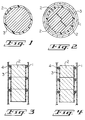
- Figure 1 is a cross-section of structured packing comprising laterally orientated channels having peripheral openings occluded with a barrier film according to the present invention.
- Figure 2 is a cross-section of a column shell having positioned therein an array of structured packing elements having a barrier film occluding those peripheral openings at the surface of the structured packing elements in non-occlusive opposition with the column shell of this invention.
- Figure 3 illustrates an embodiment of our invention where multiple segments of structured packing are vertically positioned in a column shell.
- Figure 4 depicts a preferred embodiment of our invention where multiple segments of structured packing are vertically positioned in a column shell.
- a structured packing When a structured packing is sized for use as a single element in a column, or as a vertically stacked segment, then the circumference of said element is partially or entirely occluded with a barrier film as illustrated in Figure 1.
- the structured packing When the structured packing is sized such that an array of elements are necessary to pack the column, as illustrated in Figure 2, then it is desirable to only occlude all or a portion of the peripheral openings of the laterally orientated channels which are at the surface of the structured packing intended to be in opposition to the column shell.
- non-occlusive proximation we mean that a space exists between at least a portion of the outer surface of the structured packing and the column shell.
- the barrier film may occupy all or a portion of such space.
- Figure 1 is a cross-section of structured packing 2 comprising laterally orientated channels having peripheral openings occluded with barrier film 3 according to our invention.
- barrier film 3 also totally encompasses the circumference of structured packing 2.
- Figure 2 is a cross-section of column shell 1 containing an array of structured packing elements 2 having barrier film 3 occluding those peripheral openings at the surface of structured packing elements 2 in non-occlusive opposition with column shell 1 as in our invention.
- Figure 3 illustrates an embodiment of our invention where multiple structured packing elements comprising laterally orientated channels having peripheral openings which are vertically stacked within a column shell 1.
- This shell has positioned therein multiple segments of structured packing 2; and each segment of structured packing 2 is sealed at the top against the column shell by wiper band 4.
- barrier film 3 is applied against the surface of structured packing 2, that is in non-occlusive opposition to column shell 1, to occlude the peripheral openings of the laterally orientated channels of structured packing 2.
- barrier film 3 essentially covers the total surface of structured packing 2 that is in non-occlusive opposition to column shell 1.
- Figure 4 illustrates a preferred embodiment of this invention where multiple structured packing elements, comprising laterally orientated channels having peripheral openings, are vertically stacked within a column shell 1.
- This shell has positioned therein segments of structured packing 2; and each segment of structured packing 2 is sealed near the top against the column shell by wiper band 4.
- barrier film 3 is applied against the surface of structured packing 2, that is in non-occlusive opposition to column shell 1, to occlude the peripheral openings of the laterally orientated channels of structured packing 2.
- barrier film 3 is sized and positioned such that a top portion of structured packing 2 is not occluded by barrier material 3. This configuration allows for any liquid which may accumulate in the space between column shell 1 and structured packing 2 to drain down the column.
- Vapor distribution in a column containing a ceramic structured packing and having a 16 mm gap between the column shell and the structured packing was assessed.
- the column comprised a 1 m length metal cylinder of 32.4 cm in diameter. Positioned in the column at 25 cm from the top was a ceramic structured packing 29.2 cm in diameter and 15.2 cm in height (Flexeramic® 28, Koch Engineering Company, Inc., Wichita, Kansas).
- the 16 mm gap between the structured packing and the column was sealed by wrapping the structured packing with a 16 mm polypropylene rope at either the top (T), bottom (B), or both top and bottom (T/B), as described in Table 1 in the row labelled "Rope Wrap". In run 3, the structured packing was further wrapped with paper to occlude the peripheral openings ("Paper Wrap").
- the effect of occluding the peripheral openings of structured packing on liquid-vapor contact was evaluated in a column.
- the column comprised a 0.6 m length of rectangular metal channel 9.5 cm by 10.8 cm in cross section. Positioned in the column was a ceramic structured packing 6.4 cm by 7.9 cm in cross section and 8 cm high (Flexeramic® 28). The approximate 16 mm gap between the structured packing and the column shell was sealed by wrapping the top edge of said packing with a 16 mm polypropylene rope. Water was fed to the top of the reactor through a distributor and air was fed to the bottom of the reactor also through a distributor. The relative humidity of the air exiting the top of the reactor was measured as an indication of liquid-vapor contact.
- the relative humidity of the air exiting the top of the reactor was from 70 to 85%.
- the structured packing was wrapped with a 0.8 mm thick sheet of polytetrafluoroethylene to occlude the peripheral openings. In said run, the relative humidity of the air exiting the top of the reactor was 90 to 100%.
Landscapes
- Chemical & Material Sciences (AREA)
- Physics & Mathematics (AREA)
- Thermal Sciences (AREA)
- Organic Chemistry (AREA)
- Chemical Kinetics & Catalysis (AREA)
- Physical Or Chemical Processes And Apparatus (AREA)
- Gasket Seals (AREA)
- Sealing Material Composition (AREA)
Applications Claiming Priority (2)
| Application Number | Priority Date | Filing Date | Title |
|---|---|---|---|
| US08/825,299 US5916492A (en) | 1997-03-27 | 1997-03-27 | Structured packing containing liquid-vapor contact column |
| US825299 | 1997-03-27 |
Publications (2)
| Publication Number | Publication Date |
|---|---|
| EP0867220A1 true EP0867220A1 (de) | 1998-09-30 |
| EP0867220B1 EP0867220B1 (de) | 2002-08-28 |
Family
ID=25243649
Family Applications (1)
| Application Number | Title | Priority Date | Filing Date |
|---|---|---|---|
| EP98105557A Expired - Lifetime EP0867220B1 (de) | 1997-03-27 | 1998-03-26 | Strukturierte Packung für eine Gas-Flüssigkeit-Kontaktkolonne |
Country Status (4)
| Country | Link |
|---|---|
| US (1) | US5916492A (de) |
| EP (1) | EP0867220B1 (de) |
| JP (1) | JP4749520B2 (de) |
| DE (1) | DE69807378T2 (de) |
Cited By (7)
| Publication number | Priority date | Publication date | Assignee | Title |
|---|---|---|---|---|
| EP0995491A1 (de) * | 1998-10-20 | 2000-04-26 | DEG Engineering GmbH | Reaktor für die katalytische Umsetzung von Reaktionsmedien, insbesondere von gasförmigen Reaktionsmedien |
| EP0997189A1 (de) * | 1998-10-05 | 2000-05-03 | Air Products And Chemicals, Inc. | Vorrichtungen zum Minimieren von Dampfbypass in gepakten Kolonnen und Methode zu dessen Anordnung |
| EP1256379A3 (de) * | 2001-05-08 | 2003-01-29 | QVF Engineering GmbH | Geordnete Stoffaustauschpackung mit Randabweisern |
| WO2005009608A1 (de) * | 2003-07-24 | 2005-02-03 | Basf Aktiengesellschaft | Reaktor für partialoxidationen mit thermoblechplattenmodulen |
| WO2005009609A1 (de) * | 2003-07-24 | 2005-02-03 | Basf Aktiengesellschaft | Verfahren zur herstellung von (meth)acrolein und/oder (meth)acrylsäure durch heterogen katalysierte partialoxidation von c3- und/oder c4-vorläuferverbindungen in einem reaktor mit thermoblechplattenmodulen |
| EP2514523A1 (de) * | 2011-04-22 | 2012-10-24 | Air Products And Chemicals, Inc. | Reaktor mit Strahlaufprall-Wärmeleitung |
| US8409521B2 (en) | 2008-08-13 | 2013-04-02 | Air Products And Chemicals, Inc. | Tubular reactor with jet impingement heat transfer |
Families Citing this family (2)
| Publication number | Priority date | Publication date | Assignee | Title |
|---|---|---|---|---|
| US9550685B2 (en) * | 2008-09-04 | 2017-01-24 | University Of Florida Research Foundation, Inc. | Desalination apparatus and process |
| WO2017153054A1 (de) * | 2016-03-10 | 2017-09-14 | Linde Aktiengesellschaft | Packungsanordnung, stoffaustauschkolonne und verfahren |
Citations (6)
| Publication number | Priority date | Publication date | Assignee | Title |
|---|---|---|---|---|
| DE77538C (de) * | j. GOETZ, Berlin S.W., Zimmerstr. 25 | Wellblecheinsätze für Absorptionsapparate, insbesondere für Scrubber | ||
| US4303600A (en) * | 1981-01-08 | 1981-12-01 | The Munters Corporation | Reactor column |
| EP0212202A1 (de) * | 1985-07-18 | 1987-03-04 | GebràDer Sulzer Aktiengesellschaft | Keramischer Körper sowie Verfahren und Form zur Herstellung desselben |
| US4929398A (en) * | 1989-03-29 | 1990-05-29 | Pedersen George C | Tower packing cartridge |
| DE3909995C1 (de) * | 1989-03-25 | 1990-08-30 | Schott Glaswerke, 6500 Mainz, De | |
| JPH0975711A (ja) * | 1995-09-20 | 1997-03-25 | Hitachi Ltd | 充填材シール方法 |
Family Cites Families (15)
| Publication number | Priority date | Publication date | Assignee | Title |
|---|---|---|---|---|
| US2047444A (en) * | 1935-01-14 | 1936-07-14 | Stedman Donald Frank | Packing for fractionating columns and the like |
| US2809818A (en) * | 1955-06-23 | 1957-10-15 | Munters Carl Georg | Gas and liquid contact apparatus |
| FR1377537A (fr) * | 1963-09-26 | 1964-11-06 | Tissmetal Lionel Dupont | élément de garnissage pour colonnes d'échange entre deux fluides |
| US3402105A (en) * | 1965-04-02 | 1968-09-17 | Lummus Co | Packed fractionating tower |
| CH618006A5 (de) * | 1977-05-12 | 1980-06-30 | Sulzer Ag | |
| CH617357A5 (de) * | 1977-05-12 | 1980-05-30 | Sulzer Ag | |
| CH653566A5 (de) * | 1981-07-30 | 1986-01-15 | Sulzer Ag | Kolonne fuer stoff- und direkten waermeaustausch. |
| CH653565A5 (de) * | 1981-07-30 | 1986-01-15 | Sulzer Ag | Vorrichtung zum stoff- und/oder direkten waermeaustausch oder mischen. |
| EP0070915A1 (de) * | 1981-07-30 | 1983-02-09 | GebràDer Sulzer Aktiengesellschaft | Einbauelement für eine Vorrichtung für Stoff- und direkten Wärmeaustausch und Mischen |
| US4842778A (en) * | 1985-12-23 | 1989-06-27 | Glitsch, Inc. | Apparatus for flow distribution in packed towers |
| US4882130A (en) * | 1988-06-07 | 1989-11-21 | Ngk Insulators, Ltd. | Porous structure of fluid contact |
| US5073236A (en) * | 1989-11-13 | 1991-12-17 | Gelbein Abraham P | Process and structure for effecting catalytic reactions in distillation structure |
| EP0665042A2 (de) * | 1990-12-17 | 1995-08-02 | L'air Liquide, Societe Anonyme Pour L'etude Et L'exploitation Des Procedes Georges Claude | Luftdistillationskolonne mit einer Well cross Packung |
| DE4336985C2 (de) * | 1993-10-29 | 2001-09-13 | Montz Gmbh Julius | Kolonne zum Durchführen thermischer Trennungen und/oder chemischer Reaktionen |
| US5486318A (en) * | 1994-12-29 | 1996-01-23 | The Boc Group, Inc. | Liquid-vapor contact column |
-
1997
- 1997-03-27 US US08/825,299 patent/US5916492A/en not_active Expired - Lifetime
-
1998
- 1998-03-25 JP JP07636598A patent/JP4749520B2/ja not_active Expired - Fee Related
- 1998-03-26 DE DE69807378T patent/DE69807378T2/de not_active Expired - Lifetime
- 1998-03-26 EP EP98105557A patent/EP0867220B1/de not_active Expired - Lifetime
Patent Citations (6)
| Publication number | Priority date | Publication date | Assignee | Title |
|---|---|---|---|---|
| DE77538C (de) * | j. GOETZ, Berlin S.W., Zimmerstr. 25 | Wellblecheinsätze für Absorptionsapparate, insbesondere für Scrubber | ||
| US4303600A (en) * | 1981-01-08 | 1981-12-01 | The Munters Corporation | Reactor column |
| EP0212202A1 (de) * | 1985-07-18 | 1987-03-04 | GebràDer Sulzer Aktiengesellschaft | Keramischer Körper sowie Verfahren und Form zur Herstellung desselben |
| DE3909995C1 (de) * | 1989-03-25 | 1990-08-30 | Schott Glaswerke, 6500 Mainz, De | |
| US4929398A (en) * | 1989-03-29 | 1990-05-29 | Pedersen George C | Tower packing cartridge |
| JPH0975711A (ja) * | 1995-09-20 | 1997-03-25 | Hitachi Ltd | 充填材シール方法 |
Non-Patent Citations (1)
| Title |
|---|
| PATENT ABSTRACTS OF JAPAN vol. 97, no. 7 31 July 1997 (1997-07-31) * |
Cited By (8)
| Publication number | Priority date | Publication date | Assignee | Title |
|---|---|---|---|---|
| EP0997189A1 (de) * | 1998-10-05 | 2000-05-03 | Air Products And Chemicals, Inc. | Vorrichtungen zum Minimieren von Dampfbypass in gepakten Kolonnen und Methode zu dessen Anordnung |
| EP0995491A1 (de) * | 1998-10-20 | 2000-04-26 | DEG Engineering GmbH | Reaktor für die katalytische Umsetzung von Reaktionsmedien, insbesondere von gasförmigen Reaktionsmedien |
| EP1256379A3 (de) * | 2001-05-08 | 2003-01-29 | QVF Engineering GmbH | Geordnete Stoffaustauschpackung mit Randabweisern |
| US6726188B2 (en) | 2001-05-08 | 2004-04-27 | Qvf Engineering Gmbh | Structured mass transfer packing with improved baffles |
| WO2005009608A1 (de) * | 2003-07-24 | 2005-02-03 | Basf Aktiengesellschaft | Reaktor für partialoxidationen mit thermoblechplattenmodulen |
| WO2005009609A1 (de) * | 2003-07-24 | 2005-02-03 | Basf Aktiengesellschaft | Verfahren zur herstellung von (meth)acrolein und/oder (meth)acrylsäure durch heterogen katalysierte partialoxidation von c3- und/oder c4-vorläuferverbindungen in einem reaktor mit thermoblechplattenmodulen |
| US8409521B2 (en) | 2008-08-13 | 2013-04-02 | Air Products And Chemicals, Inc. | Tubular reactor with jet impingement heat transfer |
| EP2514523A1 (de) * | 2011-04-22 | 2012-10-24 | Air Products And Chemicals, Inc. | Reaktor mit Strahlaufprall-Wärmeleitung |
Also Published As
| Publication number | Publication date |
|---|---|
| JPH10272354A (ja) | 1998-10-13 |
| DE69807378T2 (de) | 2003-04-24 |
| DE69807378D1 (de) | 2002-10-02 |
| JP4749520B2 (ja) | 2011-08-17 |
| EP0867220B1 (de) | 2002-08-28 |
| US5916492A (en) | 1999-06-29 |
Similar Documents
| Publication | Publication Date | Title |
|---|---|---|
| EP0867220B1 (de) | Strukturierte Packung für eine Gas-Flüssigkeit-Kontaktkolonne | |
| EP0428265B1 (de) | Verfahren und Einbauten zur Durchführung katalytischer Reaktionen in Destillationskolonneneinbauten | |
| KR910003123B1 (ko) | 탑 충전물(tower packing) | |
| CA1093067A (en) | Packing element of foil-like material for an exchange column | |
| KR100299275B1 (ko) | 촉매증류구조물 | |
| US4950430A (en) | Structured tower packing | |
| JP3787169B2 (ja) | 触媒蒸留用構造物 | |
| EP2086672B1 (de) | Füllkörper und diese enthaltende säule | |
| KR900700839A (ko) | 열 및 물질 교환장치 및 그 장치의 제조 방법 | |
| CA2364225C (en) | Packing for mass transfer column | |
| EP1017490B1 (de) | Packungsblock für austauschkolonne | |
| EP0916400B1 (de) | Rektifikationskolonne unter Anwendung von strukturierte Packung zur Reduktion von Wandströmung | |
| US20040140577A1 (en) | Structured packing | |
| US4303600A (en) | Reactor column | |
| EP1752214A1 (de) | Packung fuer eine Austauschkolonn | |
| US4188761A (en) | Spacer-sealer strip for reflective insulation assemblies | |
| UA51659C2 (uk) | Оправа з прокладкою для розпилювальної головки аерозольного балончикa | |
| SU1101250A1 (ru) | Тепломассообменна колонна | |
| JP3236845B2 (ja) | 内部熱交換型蒸留塔 | |
| CA1243941A (en) | Packing element for exchange column | |
| JP3085304B1 (ja) | 内部熱交換型蒸留塔 | |
| NZ236989A (en) | Reaction and distillation column having catalytic bed retained between corrugated plate pairs, and extended open areas | |
| US20200290010A1 (en) | Method and apparatus for reducing vapor bypass in a distillation column having structured packing | |
| KR100331161B1 (ko) | 증류칼럼내의벽유동을감소시키기위한열및질량교환구조물과패킹배열체 | |
| CN119015727A (zh) | 基于精馏塔填料的催化剂包及其填装结构 |
Legal Events
| Date | Code | Title | Description |
|---|---|---|---|
| PUAI | Public reference made under article 153(3) epc to a published international application that has entered the european phase |
Free format text: ORIGINAL CODE: 0009012 |
|
| AK | Designated contracting states |
Kind code of ref document: A1 Designated state(s): CH DE ES FR GB IT LI NL |
|
| AX | Request for extension of the european patent |
Free format text: AL;LT;LV;MK;RO;SI |
|
| 17P | Request for examination filed |
Effective date: 19981110 |
|
| AKX | Designation fees paid |
Free format text: CH DE ES FR GB IT LI NL |
|
| 17Q | First examination report despatched |
Effective date: 20010209 |
|
| RTI1 | Title (correction) |
Free format text: STRUCTURED PACKING FOR LIQUID-VAPOR CONTACT COLUMN |
|
| GRAG | Despatch of communication of intention to grant |
Free format text: ORIGINAL CODE: EPIDOS AGRA |
|
| GRAG | Despatch of communication of intention to grant |
Free format text: ORIGINAL CODE: EPIDOS AGRA |
|
| GRAH | Despatch of communication of intention to grant a patent |
Free format text: ORIGINAL CODE: EPIDOS IGRA |
|
| GRAH | Despatch of communication of intention to grant a patent |
Free format text: ORIGINAL CODE: EPIDOS IGRA |
|
| GRAA | (expected) grant |
Free format text: ORIGINAL CODE: 0009210 |
|
| AK | Designated contracting states |
Kind code of ref document: B1 Designated state(s): CH DE ES FR GB IT LI NL |
|
| PG25 | Lapsed in a contracting state [announced via postgrant information from national office to epo] |
Ref country code: IT Free format text: LAPSE BECAUSE OF FAILURE TO SUBMIT A TRANSLATION OF THE DESCRIPTION OR TO PAY THE FEE WITHIN THE PRESCRIBED TIME-LIMIT;WARNING: LAPSES OF ITALIAN PATENTS WITH EFFECTIVE DATE BEFORE 2007 MAY HAVE OCCURRED AT ANY TIME BEFORE 2007. THE CORRECT EFFECTIVE DATE MAY BE DIFFERENT FROM THE ONE RECORDED. Effective date: 20020828 |
|
| REG | Reference to a national code |
Ref country code: GB Ref legal event code: FG4D |
|
| REG | Reference to a national code |
Ref country code: CH Ref legal event code: EP |
|
| REG | Reference to a national code |
Ref country code: CH Ref legal event code: NV Representative=s name: E. BLUM & CO. PATENTANWAELTE |
|
| REF | Corresponds to: |
Ref document number: 69807378 Country of ref document: DE Date of ref document: 20021002 |
|
| PGFP | Annual fee paid to national office [announced via postgrant information from national office to epo] |
Ref country code: GB Payment date: 20030210 Year of fee payment: 6 |
|
| PG25 | Lapsed in a contracting state [announced via postgrant information from national office to epo] |
Ref country code: ES Free format text: LAPSE BECAUSE OF FAILURE TO SUBMIT A TRANSLATION OF THE DESCRIPTION OR TO PAY THE FEE WITHIN THE PRESCRIBED TIME-LIMIT Effective date: 20030228 |
|
| ET | Fr: translation filed | ||
| PG25 | Lapsed in a contracting state [announced via postgrant information from national office to epo] |
Ref country code: LI Free format text: LAPSE BECAUSE OF NON-PAYMENT OF DUE FEES Effective date: 20030331 Ref country code: CH Free format text: LAPSE BECAUSE OF NON-PAYMENT OF DUE FEES Effective date: 20030331 |
|
| PLBE | No opposition filed within time limit |
Free format text: ORIGINAL CODE: 0009261 |
|
| STAA | Information on the status of an ep patent application or granted ep patent |
Free format text: STATUS: NO OPPOSITION FILED WITHIN TIME LIMIT |
|
| 26N | No opposition filed |
Effective date: 20030530 |
|
| REG | Reference to a national code |
Ref country code: CH Ref legal event code: PL |
|
| PG25 | Lapsed in a contracting state [announced via postgrant information from national office to epo] |
Ref country code: GB Free format text: LAPSE BECAUSE OF NON-PAYMENT OF DUE FEES Effective date: 20040326 |
|
| GBPC | Gb: european patent ceased through non-payment of renewal fee |
Effective date: 20040326 |
|
| PGFP | Annual fee paid to national office [announced via postgrant information from national office to epo] |
Ref country code: NL Payment date: 20140308 Year of fee payment: 17 |
|
| PGFP | Annual fee paid to national office [announced via postgrant information from national office to epo] |
Ref country code: FR Payment date: 20140311 Year of fee payment: 17 |
|
| PGFP | Annual fee paid to national office [announced via postgrant information from national office to epo] |
Ref country code: DE Payment date: 20140417 Year of fee payment: 17 |
|
| REG | Reference to a national code |
Ref country code: DE Ref legal event code: R119 Ref document number: 69807378 Country of ref document: DE |
|
| REG | Reference to a national code |
Ref country code: NL Ref legal event code: MM Effective date: 20150401 |
|
| REG | Reference to a national code |
Ref country code: FR Ref legal event code: ST Effective date: 20151130 |
|
| PG25 | Lapsed in a contracting state [announced via postgrant information from national office to epo] |
Ref country code: DE Free format text: LAPSE BECAUSE OF NON-PAYMENT OF DUE FEES Effective date: 20151001 |
|
| PG25 | Lapsed in a contracting state [announced via postgrant information from national office to epo] |
Ref country code: FR Free format text: LAPSE BECAUSE OF NON-PAYMENT OF DUE FEES Effective date: 20150331 |
|
| PG25 | Lapsed in a contracting state [announced via postgrant information from national office to epo] |
Ref country code: NL Free format text: LAPSE BECAUSE OF NON-PAYMENT OF DUE FEES Effective date: 20150401 |