EP0867794B1 - Numerische steuerung, bildschirmanzeige dafür und datenein- und -ausgabeverfahren - Google Patents
Numerische steuerung, bildschirmanzeige dafür und datenein- und -ausgabeverfahren Download PDFInfo
- Publication number
- EP0867794B1 EP0867794B1 EP97944091A EP97944091A EP0867794B1 EP 0867794 B1 EP0867794 B1 EP 0867794B1 EP 97944091 A EP97944091 A EP 97944091A EP 97944091 A EP97944091 A EP 97944091A EP 0867794 B1 EP0867794 B1 EP 0867794B1
- Authority
- EP
- European Patent Office
- Prior art keywords
- data
- numerical control
- personal computer
- output
- display
- Prior art date
- Legal status (The legal status is an assumption and is not a legal conclusion. Google has not performed a legal analysis and makes no representation as to the accuracy of the status listed.)
- Expired - Lifetime
Links
Images


Classifications
-
- G—PHYSICS
- G05—CONTROLLING; REGULATING
- G05B—CONTROL OR REGULATING SYSTEMS IN GENERAL; FUNCTIONAL ELEMENTS OF SUCH SYSTEMS; MONITORING OR TESTING ARRANGEMENTS FOR SUCH SYSTEMS OR ELEMENTS
- G05B19/00—Program-control systems
- G05B19/02—Program-control systems electric
- G05B19/18—Numerical control [NC], i.e. automatically operating machines, in particular machine tools, e.g. in a manufacturing environment, so as to execute positioning, movement or co-ordinated operations by means of program data in numerical form
- G05B19/409—Numerical control [NC], i.e. automatically operating machines, in particular machine tools, e.g. in a manufacturing environment, so as to execute positioning, movement or co-ordinated operations by means of program data in numerical form characterised by using manual data input [MDI] or by using control panel, e.g. controlling functions with the panel; characterised by control panel details or by setting parameters
Definitions
- the present invention relates to a numerical control section, and more particularly, to a screen display and data input/output method for a numerical control section.
- a numerical control arrangement comprises a control section and a drive section, and the control section can be divided further into a section for controlling data input operations, and a section for generating machine control information in real time on the basis of input information and transferring commands to the drive section.
- control section is provided with a dedicated computer and software for control purposes
- the drive section comprises a servo motor or main axis motor, or a servo amplifier for driving a motor of this kind.
- a processing program is previously created or input by the input operation control section in the control section of the numerical control arrangement, and processing commands are output to the drive section in accordance with this processing program, thereby controlling the driving mechanism of the machine tool.
- the aforementioned numerical control section is also provided with a display device, which displays various information, such as the input data, control status, etc., and is used in input operations and control.
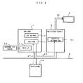
- Fig. 4 is a block circuit diagram for describing an outline of the display function of a conventional numerical control section.
- a numerical control device body hereinafter, referred to as CNC body 1 1
- CNC body 1 is connected via a bus 3 to a display circuit (hereinafter, referred to as CNC display circuit) 5, which drives a display device 4.
- the CNC body 1 is also connected via the bus 3 to input means la, such as a keyboard and a pointing device, such as a mouse and the like, and input data A is stored in a data RAM 1c.
- bit map data or graphics commands (B1) generated on the basis of the data stored in the aforementioned RAM 1c or the data in the CNC body 1 is transferred via the bus 3 to CNC display circuit 5, which generates a video signal B2 by means of analytical software stored in an internal RAM 5b, and provides required display on the display device 4.
- Reference numeral 21 denotes a data input/output circuit comprising an interface conforming to standards such as RS232C, PCMCIA, or the like, and is designed for data input/output between the body 1 and an external CNC input/output device 22 for CNC.
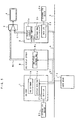
- Fig. 5 is a block diagram for describing an outline of a display function of a numerical control section incorporating a personal computer.
- a personal computer 2 is connected via a bus 3 to the numerical control device having the composition illustrated in Fig. 4 above, and both the CNC display circuit 5 and a display circuit 2a of the personal computer 2 are designed to be connectable to a common display device 4 by means of a switching circuit 6.
- the CNC body 1 When the CNC body 1 is to provide a display, it does so by transmitting a video signal B2 to the display device 4 by means of the CNC display circuit 5.
- the personal computer 2 is to provide a display, it does so by transmitting a video signal C to the display device 4 by means of a display circuit 2a.
- a switching circuit 6 is provided between the CNC display circuit 5, personal computer 2 and the display device 4 in order that data from both the CNC body and the personal computer can selectively be displayed using the common display device 4 by operating the switching circuit 6 for selecting either video signal B2 or Video signal C, thereby transmitting one of the video signals to the display device 4.
- the memory means 2b is for storing software for controlling the personal computer, and data input/output between the personal computer and an external input/output device 24 for the personal computer is made by means of a data input/output circuit 23 conforming to standards such as RS232C, PCMCIA or the like.
- a conventional numerical control section incorporating a personal computer, it is not only necessary to provide a display circuit for both the CNC body and the personal computer but also necessary to provide a switching circuit for selecting the video signal by its source, that is, the two display circuits, to transfer the selected signal to the display device. Furthermore, in the case of the conventional numerical control device, for data input/output, a separate data input/output interface for the personal computer (data input/output circuit 23), and a separate CNC data input/output interface (data input/output circuit 21) are required.
- US-A-5,530,857 discloses a method and system for shop floor control of work stations, in which a pc or workstation of a local interface unit can substitute completely for another pc or workstation of a machine tool outfit.
- a numerical control section incorporating a personal computer, and a screen display and data, input/output method for a numerical control section
- a screen display and data input/output method comprise steps of: transferring display commands generated by a numerical control device to a personal computer incorporated in the numerical control section, emulating a display circuit function of the numerical control device to convert the display commands into a video signal and transmitting the converted video signal to display means, and displaying display contents from the numerical control device on a screen of the display means using the video signal.
- an external input/output device connected to the personal computer, and to provide the steps of: transferring data from the numerical control device to the personal computer and, through which, outputting the data to the external input/output device, when the display contents from the numerical control device are displayed on a screen of the display means, and transferring numerical control data input from the external input/output device to the numerical control device.
- a personal computer is connected via a bus to a numerical control device body, and a converting means for emulating a function for displaying display commands generated by the numerical control device body is added to the circuitry of the personal computer so that display commands generated by the numerical control device body can be converted into a video signal by the converting means and displayed.
- the converting means comprises data storing means for storing display command, and conversion control means for converting display command into a video signal and controlling output thereof.
- the conversion control means comprises software storing means, the software storing means being designed for storing analytical software for analyzing and converting display command into a video signal, and drivers for controlling output of the video signal.
- the personal computer comprises data transfer means for transferring data between the personal computer and the numerical control device, and data input/output means for data input/output between the personal computer and the external input/output device.
- a numerical control section according to yet another aspect of the present invention is set out in the attached claim 10.
- a numerical control section incorporating a personal computer, it is possible to display on a screen the contents of display commands generated by the numerical control device body, without providing a display circuit or switching circuit for the numerical control device body.
- the composition of the numerical control section can be simplified and thus manufacturing costs can be reduced.
- the servo motor control system used here is virtually the same as a conventional control system, and is therefore only described in general terms here.
- 10 is a CNC control section including a computer; 11 is a common RAM; 12 is a digital servo circuit including a processor (CPU), ROM and RAM and the like; 13 is a power amplifier, such as a transistor inverter or the like; 14 is an AC servo motor; 15 is an encoder for generating pulses as the AC servo motor 14 rotates; and 16 is a rotor position detecting device for detecting the rotor phase.
- CPU processor
- 13 is a power amplifier, such as a transistor inverter or the like
- 14 is an AC servo motor
- 15 is an encoder for generating pulses as the AC servo motor 14 rotates
- 16 is a rotor position detecting device for detecting the rotor phase.
- the CNC control section 10 and common RAM 11 form the control section CTR of the numerical control system; and the common RAM 11, digital servo circuit 12, power amplifier 13, AC servo motor 14, encoder 15, and rotor position detecting device 16 form the drive section DRV of the numerical control system.
- the control section CTR is provided with a dedicated computer and software for control purposes, and the drive section DRV is provided with a servo motor or main axle motor, or a servo amplifier for driving such a motor.
- machining program is previously created or input by the input operation control section of the control section CTR, and machining commands are output to the drive section DRV in accordance with this machining program, thereby controlling the driving mechanism of the machine tool.
- a generally used CNC control section comprises a section for controlling data input operations (CNC display circuit), and a section for generating machine control information in real time on the basis of input information and transferring commands to the drive section, but the CNC control section 10 in the numerical control section incorporating a personal computer according to the present invention does not comprise a CNC display circuit, by performing the function of the CNC display circuit by emulation on the side of the personal computer.
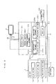
- the numerical control section incorporating a personal computer can be formed by a configuration wherein a CNC body 1 (numerical control device body) is connected to a personal computer 2 via a bus 3.
- the CNC body 1 comprises a control section CTR including at the least a CNC control section 10 and a common memory 11, as illustrated in Fig. 2, and the control section CTR comprises storing means 1b for storing software for controlling the CNC body, and storing means 1c for storing generated data.
- the storing means 1b and 1c may be constituted either of the common RAM 11 or of a dedicated RAM.
- the personal computer 2 may be composed by adding signal conversion means 20a to a generally used personal computer.
- a personal computer 2 includes in its standard sections storing means for storing software for controlling the personal computer, and a display circuit 2a. And the display contents from the personal computer 2 itself are generated by the display circuit 2a, which is a standard section, in the form of a video signal C, and are then displayed by transmitting this video signal C to the display device 4.
- a personal computer incorporated into the numerical control section according to the present invention is provided with signal converting means 20a for emulating the display function of the CNC body 1.
- This signal converting means 20a comprises data storing means 20c for receiving and storing display contents from the CNC body 1, software storing means 20b for storing analytical software for analyzing data stored in the data storing means 20c and generating a video signal, and a driver (software) for controlling the output of the video signal and transmitting it to the display device 4.
- the driver software can be formed using command designated by the user through the personal computer.
- the display contents deriving from the CNC body 1 comprise, for example, bit map data, graphics command or the like, and the analytical software analyzes the bit map data and the digital data for the graphics commands to generate analogue video signal B2.
- the personal computer 2 generates a video signal B2 corresponding to the display contents from the CNC body 1 using this analytical software, and it controls the output of the generated video signal B2 using the driver.
- the personal computer 2 transfers the display contents from the personal computer to the display device 4 by means of the display circuit 2a in the form of a video signal C, and a screen showing these display contents is displayed, and, furthermore, it transfers the display contents from the CNC body to display device 4 by means of the appended signal converting means 20a in the form of a video signal B2, and a screen showing these display contents is displayed.
- the selection regarding which of video signal B2 or video signal C is output can be made by switching in the personal computer.
- Possible methods for switching video signal include a method of switching based on key input, or the like, at the personal computer, or a method whereby the personal computer monitors the data storing means 20c periodically and generates a video signal when it detects that display contents from the CNC body are stored in the data storing means 20c, the display being switched from the personal computer display to the CNC body display in accordance with a display request, or the like.
- a RAM or the like, for example, may be used as aforesaid storing means.
- Fig. 1 it is possible to omit the CNC display circuit and the video signal switching circuit. Furthermore, even if the device composition omits the CNC display circuit, emulation can be made by means of analytical software in the personal computer, and the display contents are analyzed and converted into a video signal, so that similar operation to that performed by a CNC display circuit can be achieved.
- the operation can be modified to suit the operator's method of application, without changing the CNC body.
- composition of the personal computer 2 required for omitting the CNC display circuit and video signal switching circuit in other words, the composition of the signal converting means 20a, data storing means 20c, and software storing means 20b, is similar to that in the mode of implementation illustrated in Fig. 1.
- the data RAM 1d in the CNC body 1 functions as a data input/output buffer between the CNC body 1 and an external input/output device.
- the data RAM 25c in the personal computer 2 is a data input/output buffer between the personal computer 2 and an external input/output device, and it is connected to the microprocessor of the personal computer via an internal bus.
- the data input/output circuit 23 comprises an interface conforming to RS232C standards, PCMCIA standards, or the like, connected to the external input/output device 26, and it is connected to the internal bus of the personal computer 2.
- the analytical software 25b has a function for successively reading data of a prescribed length from the data input/output circuit 23 by means of the microprocessor in the personal computer 2 and storing the data temporarily in the data RAM 25c, when the data for personal computer is displayed on the screen of the display device 4, and storing the contents of this data in a main memory of the personal computer 2 via the microprocessor of the personal computer 2 (when data from the external input/output device 26 is to be input to the personal computer 2), as well as a function for successively reading data of a prescribed length from the main memory of the personal computer 2 by means of the microprocessor in the personal computer 2 and storing the data temporarily in the data RAM 25c each time reading is carried out, and outputting the contents of the data to the data input/output circuit 23 by means of the microprocessor in the personal computer 2 (when data from the personal computer 2 is output to the external input/output device 24).
- these functions are referred to as standard input/output functions.
- the analytical software 25b in this mode of implementation has a function of successively reading data of a prescribed length from the data input/output circuit 23 by means of the microprocessor in the personal computer 2 and storing the data temporarily, when the data for the numerical control device is displayed on the screen of the display device 4, and transferring the contents of this data, each time reading is carried out, to the data RAM 1d of the CNC body 1 through the bus and the microprocessor in the personal computer 2 (when data from the external input/output device 26 is input to the CNC body 1 via the personal computer 2) as well as a function for reading data from the data RAM 1d of the CNC body 1 by means of the microprocessor in the personal computer 2 and storing the data temporarily in the data RAM 25c, and outputting the contents thereof to the data input/output circuit 23 via the microprocessor in the personal computer 2 (when data from the CNC body 1 is output to the external input/output device 26 via the personal computer 2).
- these functions are referred to as remote input/output functions.
- the analytical software 25b comprises a driver software providing standard input/output function and a driver software providing remote input/output function.
- the driver software providing remote input/output function is selected to enable the data for the numerical control device to be input and output.
- the driver software providing the standard input/output functions is selected and data for the personal computer can be input and output.
- the CNC body 1 and external input/output device 26 can be connected indirectly through the personal computer 2, and so, even when a data input/output circuit 21, as illustrated in the conventional example in Fig. 5, and an RS232C- or PCMCIA-standard interface, or the like is not provided additionally in the CNC body 1, data can be input and output between the CNC body 1 and the external input/output device 26.
- a data input/output circuit 21 as illustrated in the conventional example in Fig. 5, and an RS232C- or PCMCIA-standard interface, or the like
- the composition of the CNC body 1 can be simplified, and, as a result, its manufacturing costs can be reduced.
Landscapes
- Engineering & Computer Science (AREA)
- Human Computer Interaction (AREA)
- Manufacturing & Machinery (AREA)
- Physics & Mathematics (AREA)
- General Physics & Mathematics (AREA)
- Automation & Control Theory (AREA)
- Numerical Control (AREA)
- Testing And Monitoring For Control Systems (AREA)
- Controls And Circuits For Display Device (AREA)
- Control By Computers (AREA)
Claims (11)
- Bildschirmanzeige- und Daten-Eingabe/Ausgabe-Verfahren für einen numerischen Steuerabschnitt für eine Maschine, wobei der Steuerabschnitt eine numerische Steuereinrichtung (1) und einen direkt mit der numerische Steuereinrichtung (1) verbundenen PC (Personal Computer) (2) umfasst, welches Verfahren gekennzeichnet ist durch Schritte zumSenden von Anzeigebefehlen, die durch die numerische Steuereinrichtung (1) erzeugt werden, an den PC (2),Nachbilden einer Anzeigeschaltungsfunktion der numerischen Steuereinrichtung (1) durch den PC (2), um die Anzeigebefehle in ein Videosignal (B2) umzuwandeln und das durch die Umwandlung entstandene Videosignal (B2) an ein Anzeigemittel (4) zu senden, undAnzeigen der Anzeigeinhalte aus der numerischen Steuereinrichtung (1) auf einem Bildschirm des Anzeigemittels (4) unter Benutzung des Videosignals (B2).
- Bildschirmanzeige- und Daten-Eingabe/Ausgabe-Verfahren für einen Steuerabschnitt nach Anspruch 1, das ferner Schritte umfaßt zumVerbinden einer externen Eingabe/Ausgabe-Einrichtung (26) mit dem PC (2),Übertragen von Daten von der numerischen Steuereinrichtung (1) zu dem PC (2) zur Ausgabe an die externe Eingabe/Ausgabe-Einrichtung (26), wenn die Anzeigeinhalte aus der numerischen Steuereinrichtung (1) auf dem Bildschirm des Anzeigemittels (4) angezeigt werden, undÜbertragen von Daten für die numerische Steuerung, die von der externen Eingabe/Ausgabe-Einrichtung (26) eingegeben werden, zu der numerischen Steuereinrichtung (1).
- Numerischer Steuerabschnitt für eine Maschine, der eine numerische Steuereinrichtung (1) umfasst, die durch einen Bus (3) direkt mit einem PC (Personal Computer) (2) verbunden ist,
dadurch gekennzeichnet, dassder Schaltung des PC (2) ein Umwandlungsmittel (20a) zum Nachbilden einer Funktion zum Anzeigen von Befehlen, die durch die numerische Steuereinrichtung (1) erzeugt werden, zugefügt ist,wodurch Anzeigebefehle, die durch die numerische Steuereinrichtung (1) erzeugt werden, durch das Umwandlungsmittel (20a) in ein Videosignal (B2) umgewandelt und angezeigt werden können. - Numerischer Steuerabschnitt nach Anspruch 3, wobei das Umwandlungsmittel (20a) umfasst:ein Datenspeichermittel (20c) zum Speichern von Anzeigebefehlen undein Umwandlungssteuermittel (20b) zum Umwandeln von Anzeigebefehlen in ein Videosignal und Steuern der Ausgabe desselben.
- Numerischer Steuerabschnitt nach Anspruch 3 oder 4, wobei das Umwandlungsmittel (20a) umfasst:ein Software-Speichermittel, das analytische Software zum Analysieren von Anzeigebefehlen speichert und die Befehle in ein Videosignal umwandelt, undeinen Treiber zum Steuern der Ausgabe des Videosignals.
- Numerischer Steuerabschnitt nach Anspruch 3, 4 oder 5, wobei der PC (2) umfasst:ein Datenübertragungsmittel (25c) zum Übertragen von Daten zwischen dem PC (2) und der numerischen Steuereinrichtung (1) undein Daten-Eingabe/Ausgabemittel (23) für eine Daten-Eingabe/Ausgabe zwischen dem PC (2) und einer externen Eingabe/Ausgabe-Einrichtung (26).
- Numerischer Steuerabschnitt nach einem der Ansprüche 3 bis 6, wobei der PC (2) umfasst: ein Videosignalschaltmittel zum Auswählen, ob Anzeigeinhalte, die durch den PC (2) selbst erzeugt werden, durch eine PC-Anzeigeschaltung (2a) in ein Videosignal (C) umgewandelt und an die Anzeigeeinrichtung (4), wo sie angezeigt werden, gesendet werden, oder ob Anzeigebefehle, die durch die numerische Steuereinrichtung (1) erzeugt werden, durch das Umwandlungsmittel (20a), das dem PC (2) zugefügt ist, in ein Videosignal (B2) umgewandelt und auf einem Bildschirm angezeigt werden.
- Numerischer Steuerabschnitt nach Anspruch 7, wenn dieser entweder direkt oder indirekt auf Anspruch 4 rückbezogen ist, wobei das Videosignalschaltmittel umfasst:ein Überwachungsmittel zum periodischen Überwachen des Datenspeichermittels (20c) undein Videosignalerzeugungsmittel zum Erzeugen eines Videosignals durch das Umwandlungsmittel (20a), wenn das Überwachungsmittel erfasst, dass Anzeigebefehlsinhalte, die durch die numerische Steuereinrichtung (1) erzeugt sind, in dem Datenspeichermittel (20c) gespeichert sind.
- Numerischer Steuerabschnitt nach Anspruch 4 oder einem der Ansprüche 5 bis 8, wenn dieser entweder direkt oder indirekt auf Anspruch 4 rückbezogen ist, wobei das Datenspeichermittel (20c) dafür bestimmt und eingerichtet ist, digitale Daten, wie Bitmap-Daten oder Grafikbefehle und dgl., welche die Anzeigeinhalte der numerischen Steuereinrichtung (1) ausmachen, zu empfangen und zu speichern, und das Umwandlungssteuermittel (20b) betreibbar ist, ein analoges Videosignal zu erzeugen, das den Anzeigeinhalten der numerischen Steuereinrichtung (1) entspricht.
- Numerischer Steuerabschnitt nach Anspruch 3, wobei die numerische Steuereinrichtung (1) einen ersten Daten-RAM (1d) umfasst, der als ein Daten-Eingabe/Ausgabepufferspeicher zwischen der numerischen Steuereinrichtung (1) und einer externen Eingabe/Ausgabe-Einrichtung (26) fungiert und der PC (2) umfasst:eine Anzeigeschaltung (2a) zum Erzeugen eines Videosignals aus den Anzeigeinhalten des PC (2) selbst,wobei das Umwandlungsmittel (20a) durch ein Signalumwandlungsmittel (20a) gebildet ist, das enthält: ein Datenspeichermittel (20c) zum Empfangen und Speichern digitaler Daten, wie Bitmap-Daten oder Grafikbefehle und dgl., welche die Anzeigeinhalte der numerischen Steuereinrichtung (1) ausmachen, und ein Datenanalysiermittel (20b) zum Analysieren der digitalen Daten, die in dem Datenspeichermittel (20c) gespeichert sind, und zum Erzeugen eines analogen Videosignals (B2), das den Anzeigeinhalten der numerischen Steuereinrichtung (1) entspricht,einen zweiten Daten-RAM (25c), der über einen internen Bus mit dem Mikroprozessor des PC (2) verbunden ist und als ein Daten-Eingabe/Ausgabepufferspeicher zwischen dem PC (2) und der externen Eingabe/Ausgabe-Einrichtung (26) fungiert,eine Daten-Eingabe/Ausgabeschaltung (23), die mit einer zum Verbinden mit der externen Eingabe/Ausgabe-Einrichtung (26) benutzten Schnittstelle versehen ist, die mit dem internen Bus des PC (2) verbunden ist, undein erstes Eingabe/Ausgabesteuermittel (25b), das besitzt: eine erste Dateneingabefunktion, durch die Daten aus der externen Eingabe/Ausgabe-Einrichtung (26) durch die Daten-Eingabe/Ausgabeschaltung (23) gelesen und vorübergehend in dem zweiten Daten-RAM (25c) gespeichert werden, wenn Anzeigeinhalte gemäß dem PC (2) selbst mittels der Anzeigeeinrichtung (4) angezeigt werden und die Inhalte, welche vorübergehend in dem zweiten Daten-RAM (25c) gespeichert sind, in dem Hauptspeicher des PC (2) gespeichert werden, und eine erste Datenausgabefunktion, durch die Daten, welche in dem Hauptspeicher des PC (2) gespeichert sind, gelesen und vorübergehend in dem zweiten Daten-RAM (25c) gespeichert werden und diese vorübergehend gespeicherten Inhalte abgerufen werden, um an die Daten-Eingabe/Ausgabeschaltung (23) ausgegeben zu werden, und die Daten zu der externen Eingabe/Ausgabe-Einrichtung (26) übertragen werden.
- Numerische Steuereinrichtung nach Anspruch 10, wobei das Analysiermittel umfasst: ein zweites Eingabe/Ausgabesteuermittel zum Durchführeneiner zweiten Dateneingabefunktion, durch die Daten aus einer externen Eingabe/Ausgabe-Einrichtung (26) mittels der Daten-Eingabe/Ausgabeschaltung (23) gelesen und vorübergehend in dem zweiten Daten-RAM (25c) gespeichert werden, wenn Inhalte aus der numerischen Steuereinrichtung (1) mittels der Anzeigeeinrichtung (4) angezeigt werden, und die Inhalte, welche vorübergehend in dem zweiten Daten-RAM (25c) gespeichert sind, zu dem ersten Daten-RAM (1d) der numerischen Steuereinrichtung (1) übertragen werden, undeiner zweiten Datenausgabefunktion, durch die Daten aus dem ersten Daten-RAM (1d) in der numerischen Steuereinrichtung (1) gelesen und zu dem zweiten Daten-RAM (25c) übertragen werden, um darin vorübergehend gespeichert zu werden, und die Inhalte an die Daten-Eingabe/Ausgabeschaltung (23) ausgegeben und zu der externen Eingabe/Ausgabe-Einrichtung (26) übertragen werden.
Applications Claiming Priority (7)
| Application Number | Priority Date | Filing Date | Title |
|---|---|---|---|
| JP284573/96 | 1996-10-08 | ||
| JP28457396 | 1996-10-08 | ||
| JP28457396 | 1996-10-08 | ||
| JP197974/97 | 1997-07-09 | ||
| JP19797497A JPH10171516A (ja) | 1996-10-08 | 1997-07-09 | 数値制御装置および数値制御装置の画面表示,データ入出力方法 |
| JP19797497 | 1997-07-09 | ||
| PCT/JP1997/003612 WO1998015881A1 (fr) | 1996-10-08 | 1997-10-08 | Controleur numerique, son affichage et procede d'entree/sortie des donnees |
Publications (3)
| Publication Number | Publication Date |
|---|---|
| EP0867794A1 EP0867794A1 (de) | 1998-09-30 |
| EP0867794A4 EP0867794A4 (de) | 1998-12-16 |
| EP0867794B1 true EP0867794B1 (de) | 2000-04-19 |
Family
ID=26510689
Family Applications (1)
| Application Number | Title | Priority Date | Filing Date |
|---|---|---|---|
| EP97944091A Expired - Lifetime EP0867794B1 (de) | 1996-10-08 | 1997-10-08 | Numerische steuerung, bildschirmanzeige dafür und datenein- und -ausgabeverfahren |
Country Status (5)
| Country | Link |
|---|---|
| US (1) | US6285915B1 (de) |
| EP (1) | EP0867794B1 (de) |
| JP (1) | JPH10171516A (de) |
| DE (1) | DE69701722T2 (de) |
| WO (1) | WO1998015881A1 (de) |
Families Citing this family (6)
| Publication number | Priority date | Publication date | Assignee | Title |
|---|---|---|---|---|
| US6397124B1 (en) * | 1999-05-11 | 2002-05-28 | Falcon Machine Tools Co., Ltd. | Interactive system between machine tool and operator |
| JP2007026171A (ja) * | 2005-07-19 | 2007-02-01 | Fanuc Ltd | 数値制御装置 |
| JP5321049B2 (ja) * | 2008-12-26 | 2013-10-23 | 横河電機株式会社 | 分散型制御システム |
| JP4927975B2 (ja) * | 2010-07-06 | 2012-05-09 | ファナック株式会社 | パソコン機能を有する数値制御装置 |
| JP5469190B2 (ja) * | 2012-03-26 | 2014-04-09 | ファナック株式会社 | 対話画面で加工シミュレーションが可能な加工プログラム作成装置 |
| CN107272661A (zh) * | 2017-07-26 | 2017-10-20 | 华中科技大学 | 一种基于机床仿真模型的数控装置运动控制性能测试系统 |
Family Cites Families (17)
| Publication number | Priority date | Publication date | Assignee | Title |
|---|---|---|---|---|
| JPS59216208A (ja) * | 1983-05-23 | 1984-12-06 | Mitsubishi Electric Corp | 数値制御装置 |
| JPS59225404A (ja) * | 1983-06-06 | 1984-12-18 | Fanuc Ltd | カラ−デイスプレイ装置を備なえた数値制御システム |
| JPS61288959A (ja) * | 1985-02-15 | 1986-12-19 | Toyoda Mach Works Ltd | 対話形数値制御研削盤のデータ入力装置 |
| JPS63136107A (ja) | 1986-11-27 | 1988-06-08 | Mitsubishi Heavy Ind Ltd | Ncデ−タ入力制御装置 |
| US5530857A (en) * | 1987-07-02 | 1996-06-25 | Bull, S.A. | Automated shop floor control system and method of operation thereof |
| US5317501A (en) * | 1987-10-13 | 1994-05-31 | Bernhard Hilpert | Control system for a numerically controlled machine |
| JPH06944B2 (ja) | 1989-03-13 | 1994-01-05 | 株式会社ライムズ | 結晶質酸化アルミニウム薄膜の形成方法 |
| JPH0484204A (ja) | 1990-07-26 | 1992-03-17 | Fanuc Ltd | 数値制御装置の表示方式 |
| JPH04213760A (ja) * | 1990-12-10 | 1992-08-04 | Nec Corp | オンライン帳票発行方式 |
| JP2876576B2 (ja) | 1992-02-26 | 1999-03-31 | 三菱電機株式会社 | 数値制御装置 |
| JPH05282031A (ja) * | 1992-03-31 | 1993-10-29 | Shin Meiwa Ind Co Ltd | 情報モニタリング装置 |
| JPH06318110A (ja) * | 1993-05-07 | 1994-11-15 | Fanuc Ltd | Mmcユニット |
| US5703702A (en) * | 1993-09-08 | 1997-12-30 | Crane; Patrick E. | Holographic synthesis |
| JPH0916239A (ja) | 1995-06-30 | 1997-01-17 | Toshiba Mach Co Ltd | パソコン型数値制御装置のリモート表示方法 |
| JP3020456U (ja) * | 1995-07-13 | 1996-01-23 | ヤマハ株式会社 | ロボット制御装置 |
| JP3080300B2 (ja) | 1996-07-26 | 2000-08-21 | キヤノン株式会社 | 液晶素子 |
| JP3020456B2 (ja) | 1996-12-27 | 2000-03-15 | 富士化水工業株式会社 | 有機性廃水処理方法および装置 |
-
1997
- 1997-07-09 JP JP19797497A patent/JPH10171516A/ja active Pending
- 1997-10-08 EP EP97944091A patent/EP0867794B1/de not_active Expired - Lifetime
- 1997-10-08 DE DE69701722T patent/DE69701722T2/de not_active Expired - Lifetime
- 1997-10-08 WO PCT/JP1997/003612 patent/WO1998015881A1/ja not_active Ceased
- 1997-10-08 US US09/077,834 patent/US6285915B1/en not_active Expired - Lifetime
Also Published As
| Publication number | Publication date |
|---|---|
| EP0867794A1 (de) | 1998-09-30 |
| JPH10171516A (ja) | 1998-06-26 |
| US6285915B1 (en) | 2001-09-04 |
| DE69701722T2 (de) | 2000-08-10 |
| DE69701722D1 (de) | 2000-05-25 |
| EP0867794A4 (de) | 1998-12-16 |
| WO1998015881A1 (fr) | 1998-04-16 |
Similar Documents
| Publication | Publication Date | Title |
|---|---|---|
| US6853881B2 (en) | Robot information processing system | |
| US5687295A (en) | Jog feed information display apparatus for a robot | |
| EP0867794B1 (de) | Numerische steuerung, bildschirmanzeige dafür und datenein- und -ausgabeverfahren | |
| US6396030B1 (en) | Robot control device | |
| EP0070654A2 (de) | Bewegungssteuerung | |
| EP1249746A2 (de) | Numerische Steuerung | |
| US20030160149A1 (en) | Method and apparatus for real time synchronous control of laser beams and multi-axis machines | |
| JP2646776B2 (ja) | 視覚補正位置決め装置 | |
| JPH0816220A (ja) | プログラマブルシーケンスコントローラ | |
| JPS61154493A (ja) | サーボモータの駆動制御装置 | |
| EP0942343A2 (de) | Numerisches Steuerungs Gerät | |
| US5966303A (en) | Position control signal generating circuit | |
| KR100188683B1 (ko) | 공작기계의 직접수치제어 시스템 | |
| JP2000010614A (ja) | ユーザインタフェース利用ロボット操作方法及びシステム装置並びにそのプログラムを記録した記録媒体 | |
| JPH01156805A (ja) | 産業用ロボットの制御装置 | |
| KR100383896B1 (ko) | 기기 제어 시스템 | |
| JPH1069309A (ja) | 数値制御装置 | |
| JPH0217509A (ja) | Cad/cam装置 | |
| JPH01195509A (ja) | Dnc装置 | |
| JP3296477B2 (ja) | ラダープログラムのデバッグ装置 | |
| JP2002272173A (ja) | 電動機制御装置 | |
| KR19980021326A (ko) | 동시에 2축(x, y)을 제어하는 cnc 제어장치 및 방법 | |
| JPH08320757A (ja) | データ転送システム | |
| JPH08314531A (ja) | コンピュータ制御による工作機械及び一般産業機械の補助周辺装置における動作条件変更装置 | |
| JPH045709A (ja) | 数値制御プログラム入力装置 |
Legal Events
| Date | Code | Title | Description |
|---|---|---|---|
| PUAI | Public reference made under article 153(3) epc to a published international application that has entered the european phase |
Free format text: ORIGINAL CODE: 0009012 |
|
| 17P | Request for examination filed |
Effective date: 19980702 |
|
| AK | Designated contracting states |
Kind code of ref document: A1 Designated state(s): DE |
|
| A4 | Supplementary search report drawn up and despatched |
Effective date: 19981104 |
|
| AK | Designated contracting states |
Kind code of ref document: A4 Designated state(s): DE |
|
| 17Q | First examination report despatched |
Effective date: 19990310 |
|
| GRAG | Despatch of communication of intention to grant |
Free format text: ORIGINAL CODE: EPIDOS AGRA |
|
| GRAG | Despatch of communication of intention to grant |
Free format text: ORIGINAL CODE: EPIDOS AGRA |
|
| GRAH | Despatch of communication of intention to grant a patent |
Free format text: ORIGINAL CODE: EPIDOS IGRA |
|
| GRAH | Despatch of communication of intention to grant a patent |
Free format text: ORIGINAL CODE: EPIDOS IGRA |
|
| GRAA | (expected) grant |
Free format text: ORIGINAL CODE: 0009210 |
|
| AK | Designated contracting states |
Kind code of ref document: B1 Designated state(s): DE |
|
| REF | Corresponds to: |
Ref document number: 69701722 Country of ref document: DE Date of ref document: 20000525 |
|
| EN | Fr: translation not filed | ||
| PLBE | No opposition filed within time limit |
Free format text: ORIGINAL CODE: 0009261 |
|
| STAA | Information on the status of an ep patent application or granted ep patent |
Free format text: STATUS: NO OPPOSITION FILED WITHIN TIME LIMIT |
|
| 26N | No opposition filed | ||
| REG | Reference to a national code |
Ref country code: DE Ref legal event code: R082 Ref document number: 69701722 Country of ref document: DE Representative=s name: HASELTINE LAKE LLP, DE |
|
| PGFP | Annual fee paid to national office [announced via postgrant information from national office to epo] |
Ref country code: DE Payment date: 20161004 Year of fee payment: 20 |
|
| REG | Reference to a national code |
Ref country code: DE Ref legal event code: R071 Ref document number: 69701722 Country of ref document: DE |