EP0868302B1 - Präge-und kaschiermaschine zum verkleben von geprägten schichten - Google Patents
Präge-und kaschiermaschine zum verkleben von geprägten schichten Download PDFInfo
- Publication number
- EP0868302B1 EP0868302B1 EP96941808A EP96941808A EP0868302B1 EP 0868302 B1 EP0868302 B1 EP 0868302B1 EP 96941808 A EP96941808 A EP 96941808A EP 96941808 A EP96941808 A EP 96941808A EP 0868302 B1 EP0868302 B1 EP 0868302B1
- Authority
- EP
- European Patent Office
- Prior art keywords
- protuberances
- embossing
- alignment
- cylinders
- directions
- Prior art date
- Legal status (The legal status is an assumption and is not a legal conclusion. Google has not performed a legal analysis and makes no representation as to the accuracy of the status listed.)
- Expired - Lifetime
Links
- 238000004049 embossing Methods 0.000 title claims abstract description 126
- 238000010030 laminating Methods 0.000 title claims abstract description 17
- 238000004026 adhesive bonding Methods 0.000 title description 4
- 238000003475 lamination Methods 0.000 claims abstract description 4
- 239000000463 material Substances 0.000 claims description 26
- 238000000034 method Methods 0.000 claims description 10
- 238000011161 development Methods 0.000 claims description 9
- 238000005304 joining Methods 0.000 claims description 4
- 230000002093 peripheral effect Effects 0.000 claims description 2
- 239000011295 pitch Substances 0.000 claims 6
- 239000010410 layer Substances 0.000 description 64
- 230000005540 biological transmission Effects 0.000 description 6
- 239000000047 product Substances 0.000 description 6
- 238000003754 machining Methods 0.000 description 5
- 239000000853 adhesive Substances 0.000 description 3
- 230000001070 adhesive effect Effects 0.000 description 3
- 238000010586 diagram Methods 0.000 description 3
- 238000004804 winding Methods 0.000 description 3
- 239000012467 final product Substances 0.000 description 2
- 238000004519 manufacturing process Methods 0.000 description 2
- 238000012545 processing Methods 0.000 description 2
- 238000013459 approach Methods 0.000 description 1
- 238000007796 conventional method Methods 0.000 description 1
- 230000000694 effects Effects 0.000 description 1
- 239000013529 heat transfer fluid Substances 0.000 description 1
- 230000003993 interaction Effects 0.000 description 1
- 239000002365 multiple layer Substances 0.000 description 1
- 239000011265 semifinished product Substances 0.000 description 1
- 239000000126 substance Substances 0.000 description 1
Images







Classifications
-
- B—PERFORMING OPERATIONS; TRANSPORTING
- B31—MAKING ARTICLES OF PAPER, CARDBOARD OR MATERIAL WORKED IN A MANNER ANALOGOUS TO PAPER; WORKING PAPER, CARDBOARD OR MATERIAL WORKED IN A MANNER ANALOGOUS TO PAPER
- B31F—MECHANICAL WORKING OR DEFORMATION OF PAPER, CARDBOARD OR MATERIAL WORKED IN A MANNER ANALOGOUS TO PAPER
- B31F1/00—Mechanical deformation without removing material, e.g. in combination with laminating
- B31F1/07—Embossing, i.e. producing impressions formed by locally deep-drawing, e.g. using rolls provided with complementary profiles
-
- B—PERFORMING OPERATIONS; TRANSPORTING
- B31—MAKING ARTICLES OF PAPER, CARDBOARD OR MATERIAL WORKED IN A MANNER ANALOGOUS TO PAPER; WORKING PAPER, CARDBOARD OR MATERIAL WORKED IN A MANNER ANALOGOUS TO PAPER
- B31F—MECHANICAL WORKING OR DEFORMATION OF PAPER, CARDBOARD OR MATERIAL WORKED IN A MANNER ANALOGOUS TO PAPER
- B31F2201/00—Mechanical deformation of paper or cardboard without removing material
- B31F2201/07—Embossing
- B31F2201/0707—Embossing by tools working continuously
- B31F2201/0715—The tools being rollers
- B31F2201/0717—Methods and means for forming the embossments
-
- B—PERFORMING OPERATIONS; TRANSPORTING
- B31—MAKING ARTICLES OF PAPER, CARDBOARD OR MATERIAL WORKED IN A MANNER ANALOGOUS TO PAPER; WORKING PAPER, CARDBOARD OR MATERIAL WORKED IN A MANNER ANALOGOUS TO PAPER
- B31F—MECHANICAL WORKING OR DEFORMATION OF PAPER, CARDBOARD OR MATERIAL WORKED IN A MANNER ANALOGOUS TO PAPER
- B31F2201/00—Mechanical deformation of paper or cardboard without removing material
- B31F2201/07—Embossing
- B31F2201/0707—Embossing by tools working continuously
- B31F2201/0715—The tools being rollers
- B31F2201/0723—Characteristics of the rollers
- B31F2201/0733—Pattern
- B31F2201/0735—Pattern inclined with respect to the axis of the roller
-
- B—PERFORMING OPERATIONS; TRANSPORTING
- B31—MAKING ARTICLES OF PAPER, CARDBOARD OR MATERIAL WORKED IN A MANNER ANALOGOUS TO PAPER; WORKING PAPER, CARDBOARD OR MATERIAL WORKED IN A MANNER ANALOGOUS TO PAPER
- B31F—MECHANICAL WORKING OR DEFORMATION OF PAPER, CARDBOARD OR MATERIAL WORKED IN A MANNER ANALOGOUS TO PAPER
- B31F2201/00—Mechanical deformation of paper or cardboard without removing material
- B31F2201/07—Embossing
- B31F2201/0707—Embossing by tools working continuously
- B31F2201/0715—The tools being rollers
- B31F2201/0723—Characteristics of the rollers
- B31F2201/0738—Cross sectional profile of the embossments
-
- B—PERFORMING OPERATIONS; TRANSPORTING
- B31—MAKING ARTICLES OF PAPER, CARDBOARD OR MATERIAL WORKED IN A MANNER ANALOGOUS TO PAPER; WORKING PAPER, CARDBOARD OR MATERIAL WORKED IN A MANNER ANALOGOUS TO PAPER
- B31F—MECHANICAL WORKING OR DEFORMATION OF PAPER, CARDBOARD OR MATERIAL WORKED IN A MANNER ANALOGOUS TO PAPER
- B31F2201/00—Mechanical deformation of paper or cardboard without removing material
- B31F2201/07—Embossing
- B31F2201/0707—Embossing by tools working continuously
- B31F2201/0715—The tools being rollers
- B31F2201/0753—Roller supporting, positioning, driving means
-
- B—PERFORMING OPERATIONS; TRANSPORTING
- B31—MAKING ARTICLES OF PAPER, CARDBOARD OR MATERIAL WORKED IN A MANNER ANALOGOUS TO PAPER; WORKING PAPER, CARDBOARD OR MATERIAL WORKED IN A MANNER ANALOGOUS TO PAPER
- B31F—MECHANICAL WORKING OR DEFORMATION OF PAPER, CARDBOARD OR MATERIAL WORKED IN A MANNER ANALOGOUS TO PAPER
- B31F2201/00—Mechanical deformation of paper or cardboard without removing material
- B31F2201/07—Embossing
- B31F2201/0758—Characteristics of the embossed product
- B31F2201/0761—Multi-layered
- B31F2201/0769—Multi-layered the layers being shifted
-
- B—PERFORMING OPERATIONS; TRANSPORTING
- B31—MAKING ARTICLES OF PAPER, CARDBOARD OR MATERIAL WORKED IN A MANNER ANALOGOUS TO PAPER; WORKING PAPER, CARDBOARD OR MATERIAL WORKED IN A MANNER ANALOGOUS TO PAPER
- B31F—MECHANICAL WORKING OR DEFORMATION OF PAPER, CARDBOARD OR MATERIAL WORKED IN A MANNER ANALOGOUS TO PAPER
- B31F2201/00—Mechanical deformation of paper or cardboard without removing material
- B31F2201/07—Embossing
- B31F2201/0782—Layout of the complete embossing machine, of the embossing line
-
- B—PERFORMING OPERATIONS; TRANSPORTING
- B31—MAKING ARTICLES OF PAPER, CARDBOARD OR MATERIAL WORKED IN A MANNER ANALOGOUS TO PAPER; WORKING PAPER, CARDBOARD OR MATERIAL WORKED IN A MANNER ANALOGOUS TO PAPER
- B31F—MECHANICAL WORKING OR DEFORMATION OF PAPER, CARDBOARD OR MATERIAL WORKED IN A MANNER ANALOGOUS TO PAPER
- B31F2201/00—Mechanical deformation of paper or cardboard without removing material
- B31F2201/07—Embossing
- B31F2201/0784—Auxiliary operations
- B31F2201/0787—Applying adhesive
-
- Y—GENERAL TAGGING OF NEW TECHNOLOGICAL DEVELOPMENTS; GENERAL TAGGING OF CROSS-SECTIONAL TECHNOLOGIES SPANNING OVER SEVERAL SECTIONS OF THE IPC; TECHNICAL SUBJECTS COVERED BY FORMER USPC CROSS-REFERENCE ART COLLECTIONS [XRACs] AND DIGESTS
- Y10—TECHNICAL SUBJECTS COVERED BY FORMER USPC
- Y10T—TECHNICAL SUBJECTS COVERED BY FORMER US CLASSIFICATION
- Y10T156/00—Adhesive bonding and miscellaneous chemical manufacture
- Y10T156/10—Methods of surface bonding and/or assembly therefor
- Y10T156/1002—Methods of surface bonding and/or assembly therefor with permanent bending or reshaping or surface deformation of self sustaining lamina
- Y10T156/1007—Running or continuous length work
- Y10T156/1023—Surface deformation only [e.g., embossing]
-
- Y—GENERAL TAGGING OF NEW TECHNOLOGICAL DEVELOPMENTS; GENERAL TAGGING OF CROSS-SECTIONAL TECHNOLOGIES SPANNING OVER SEVERAL SECTIONS OF THE IPC; TECHNICAL SUBJECTS COVERED BY FORMER USPC CROSS-REFERENCE ART COLLECTIONS [XRACs] AND DIGESTS
- Y10—TECHNICAL SUBJECTS COVERED BY FORMER USPC
- Y10T—TECHNICAL SUBJECTS COVERED BY FORMER US CLASSIFICATION
- Y10T156/00—Adhesive bonding and miscellaneous chemical manufacture
- Y10T156/10—Methods of surface bonding and/or assembly therefor
- Y10T156/1002—Methods of surface bonding and/or assembly therefor with permanent bending or reshaping or surface deformation of self sustaining lamina
- Y10T156/1039—Surface deformation only of sandwich or lamina [e.g., embossed panels]
-
- Y—GENERAL TAGGING OF NEW TECHNOLOGICAL DEVELOPMENTS; GENERAL TAGGING OF CROSS-SECTIONAL TECHNOLOGIES SPANNING OVER SEVERAL SECTIONS OF THE IPC; TECHNICAL SUBJECTS COVERED BY FORMER USPC CROSS-REFERENCE ART COLLECTIONS [XRACs] AND DIGESTS
- Y10—TECHNICAL SUBJECTS COVERED BY FORMER USPC
- Y10T—TECHNICAL SUBJECTS COVERED BY FORMER US CLASSIFICATION
- Y10T156/00—Adhesive bonding and miscellaneous chemical manufacture
- Y10T156/17—Surface bonding means and/or assemblymeans with work feeding or handling means
- Y10T156/1702—For plural parts or plural areas of single part
- Y10T156/1712—Indefinite or running length work
- Y10T156/1737—Discontinuous, spaced area, and/or patterned pressing
-
- Y—GENERAL TAGGING OF NEW TECHNOLOGICAL DEVELOPMENTS; GENERAL TAGGING OF CROSS-SECTIONAL TECHNOLOGIES SPANNING OVER SEVERAL SECTIONS OF THE IPC; TECHNICAL SUBJECTS COVERED BY FORMER USPC CROSS-REFERENCE ART COLLECTIONS [XRACs] AND DIGESTS
- Y10—TECHNICAL SUBJECTS COVERED BY FORMER USPC
- Y10T—TECHNICAL SUBJECTS COVERED BY FORMER US CLASSIFICATION
- Y10T428/00—Stock material or miscellaneous articles
- Y10T428/24—Structurally defined web or sheet [e.g., overall dimension, etc.]
- Y10T428/24355—Continuous and nonuniform or irregular surface on layer or component [e.g., roofing, etc.]
- Y10T428/24446—Wrinkled, creased, crinkled or creped
- Y10T428/24455—Paper
- Y10T428/24463—Plural paper components
-
- Y—GENERAL TAGGING OF NEW TECHNOLOGICAL DEVELOPMENTS; GENERAL TAGGING OF CROSS-SECTIONAL TECHNOLOGIES SPANNING OVER SEVERAL SECTIONS OF THE IPC; TECHNICAL SUBJECTS COVERED BY FORMER USPC CROSS-REFERENCE ART COLLECTIONS [XRACs] AND DIGESTS
- Y10—TECHNICAL SUBJECTS COVERED BY FORMER USPC
- Y10T—TECHNICAL SUBJECTS COVERED BY FORMER US CLASSIFICATION
- Y10T428/00—Stock material or miscellaneous articles
- Y10T428/24—Structurally defined web or sheet [e.g., overall dimension, etc.]
- Y10T428/24479—Structurally defined web or sheet [e.g., overall dimension, etc.] including variation in thickness
- Y10T428/24612—Composite web or sheet
Definitions
- the invention relates to an embossing machine of the tip-to-tip type comprising two embossing cylinders, each provided with corresponding sets of protuberances, and two pressure rollers, each interacting with a corresponding one of the said two embossing cylinders, to emboss two layers of material in strip form separately and then join the said layers together, using adhesive or some other substance, to form a multiple-layer material in strip form.
- the invention also relates to a laminated embossed product, for example a strip of paper wound into a roll, a serviette or a paper tissue or some other item, comprising at least two separately embossed layers, each of the two layers having the same embossed pattern, consisting of a plurality of protuberances disposed in a repeated geometrical pattern in two directions of alignment forming between them an angle other than zero.
- a laminated embossed product for example a strip of paper wound into a roll, a serviette or a paper tissue or some other item, comprising at least two separately embossed layers, each of the two layers having the same embossed pattern, consisting of a plurality of protuberances disposed in a repeated geometrical pattern in two directions of alignment forming between them an angle other than zero.
- the invention further relates to a method of embossing a strip material, comprising the stages of embossing a first layer of indefinite length by forming a first set of protuberances thereon; embossing a second layer of indefinite length, separately from the first, by forming a second set of protuberances thereon; and joining the said two layers to form the said strip material.
- the embossing machine and the method to which the present invention relates are commonly used for the processing of paper layers for the purpose of forming a semi-finished product intended for the production of rolls of toilet paper, rolls of kitchen towels, tissues, paper serviettes, and the like.
- the protuberances on the two cylinders are aligned in spirals inclined with respect to the axes of the corresponding cylinders, in order to achieve certain advantageous results.
- the protuberances of the two cylinders are aligned along lines parallel to the axes of the corresponding cylinders, as described in US-A-3,414,459.
- the two embossing cylinders are not only symmetrical with respect to each other, but are identical. In both cases, a perfect phase matching is required between the two cylinders, and this requires adjustment time and specialist personnel.
- One object of the present invention is to produce an embossing and laminating machine which overcomes the aforesaid problems of the prior art, and which requires no phase matching between the embossing cylinders.
- the invention is based on the recognition of the fact that it is possible to have partial correspondence between the protuberances of one cylinder and the protuberances of the other cylinder by using the same pitch in the alignment of the protuberances on the two cylinders and appropriately varying the inclination of the directions of alignment of the protuberances on the two cylinders.
- two identical directions of alignment of the protuberances on the two cylinders are made to be inclined in the same direction with respect to the axes of the corresponding cylinders, in other words with respect to the corresponding generatrices.
- the protuberances are aligned in two right-hand spirals or in two left-hand spirals on the two cylinders. Additionally, the protuberances are disposed in such a way that there are no alignments parallel to the axes of the corresponding embossing cylinders, contrary to what is the case in US-A-3,414,459.
- the embossing cylinders are made symmetrical (EP-A-0,370,972) or symmetrical and identical and with alignments parallel to the axes of the cylinders (US-A-3,414,972) in order to have the protuberances of one cylinder exactly match the protuberances of the other in the contact area, in other words in the area in which the embossed layers are laminated and joined, according to the present invention the cylinders are not symmetrical, in order to avoid having the protuberances in the contact area matching exactly, although the pitch between the protuberances remains the same. This enables the embossing cylinders to be made with the same tool.
- the two homologous directions of alignment of the protuberances of the two cylinders are inclined in opposite directions, but form different angles with the axes of the corresponding cylinders.
- an embossed sheet product comprising at least two separately embossed layers, each of which has the same embossed pattern, consisting of a plurality of protuberances disposed in a repeated geometrical pattern in two directions of alignment forming an angle other than zero between them, in which the directions of alignment of the protuberances of the first layer are inclined with respect to the corresponding directions of alignment of the protuberances of the second layer.
- the protuberances of the first and of the second layer are therefore in contact with each other in restricted areas of the surface development of the final embossed material.
- the embossing method according to the invention is therefore characterized in that the homologous directions of alignment of the protuberances of the first and second layers are formed in such a way that, when the two layers are joined, the said directions of alignment are not parallel to each other, the protuberances of the first layer corresponding to the protuberances of the second layer only in restricted areas of the development of the strip material.
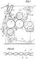
- a known embossing and laminating machine of the tip-to-tip type indicated overall by the number 1, will be described in a summary way initially.
- Two embossing cylinders 3 and 5 disposed with parallel axes and having their surfaces provided with protuberances for embossing, are mounted on the frame of the machine 1. In the nip formed by the two cylinders 3 and 5, the protuberances (or rather some of them, as will be explained subsequently) are in contact with each other.
- the embossing cylinder 3 interacts with a pressure roller 7 which may also be provided with an embossed surface, or may be covered with a yielding material such as rubber or the like.
- the number 9 indicates a second pressure roller similar to the roller 7 and interacting with the embossing cylinder 5.
- the two pressure rollers 7 and 9 are mounted on corresponding moving elements 7A and 9A which are hinged and subject to an elastic force, for example via two cylinder and piston systems 7B, 9B which press the corresponding pressure rollers against the corresponding embossing cylinders 3 and 5.
- N3 and N5 indicate two layers of paper material or the like which are fed between the embossing cylinder 3 and the pressure roller 7 and between the embossing cylinder 5 and the pressure roller 9 respectively, so that they are embossed separately.
- the two embossed layers remain engaged with the corresponding embossing cylinders 3 and 5 and, after an adhesive has been applied by the unit 14 to the protuberances of the layer N3, are joined together in the nip between the two embossing cylinders 3 and 5, where the protuberances of one embossing cylinder move at a distance which is less than the combined thickness of the two layers N3 and N5 from the protuberances of the other cylinder.
- the protuberances of the two embossing cylinders 3 and 5 are made symmetrical, so that all the protuberances of a first embossing cylinder touch or brush against the corresponding protuberances of the other cylinder in the area of tangency of the embossing cylinders.
- the strip material which is produced is thus joined tip-to-tip over its whole surface.
- the two embossing cylinders 3 and 5 are made in such a way that the same pattern is embossed on both cylinders, but is disposed at inclinations such that there is no superimposition, in other words correspondence, between all the protuberances of one cylinder and all the protuberances of the other cylinder, but there is a superimposition or coincidence in certain areas.
- the protuberances P3 of the first set are aligned in a first and second direction of alignment indicated by Lx 3 and Ly 3 , forming between them an angle ⁇ other than zero.
- the protuberances p3 are disposed with the same pitch along Lx 3 and along Ly 3 , but this need not be so.
- the direction Lx 3 forms an angle ⁇ 3 of 2° with the direction of the axis A3 of the first embossing cylinder 3.
- the protuberances P5 of the second set, on the embossing cylinder 5, are aligned in a third and fourth direction of alignment, indicated by Lx 5 and Ly 5 in Fig. 3.
- the directions of alignment Lx 5 and Ly 5 form between them the same angle ⁇ (or at least an angle very close to ⁇ , for example with a variation of approximately 1-3°), and are orientated in the same direction with respect to the axis A5 of the embossing cylinder 5.
- the direction LX 5 is inclined downwards from left to right in Fig. 3, as is the direction Lx 3 in Fig. 2.
- the angle ⁇ 5 formed by the third direction of alignment Lx 5 with the axis A5 of the embossing cylinder 5 is, in this embodiment, different from the angle ⁇ 5 and is equal to 6°.
- Protuberances P3' and P5' are impressed on the two layers N3 and N5 in a pattern corresponding to that formed by the protuberances P3 and P5 on the two embossing cylinders 3 and 5 respectively. Consequently, after the two layers have been joined, there is no superimposition or coincidence of each protuberance of one layer with a corresponding protuberance of the other layer, but, as shown in Fig. 4, there is a correspondence in certain areas. The areas in which the protuberances coincide are separated from each other by areas in which the protuberances on one layer do not coincide with the protuberances of the other layer.
- the areas in which the protuberances P3' and P5' coincide are aligned in two alignments which are not parallel to the axes A3 and A5 of the two embossing cylinders 3 and 5. This means that, as the two layers N3 and N5 are joined, the protuberances P3 and P5 of the two embossing cylinders come into contact gradually in the area of lamination (in other words, of joining) of the strips, with an advantageous reduction in the vibration of the machine, mechanical stresses and noise.
- Lx 3 ', Ly 3 ' and Lx 5 ', Ly 5 ' indicate the directions of alignment of the protuberances P3' and P5' on the first and second layer respectively.
- the letter F indicates the direction of advance of the strip material leaving the embossing machine.
- Fig. 6 shows a schematic enlargement of Fig. 5, where the areas of coincidence of the protuberances P3' and P5' are clearly visible.
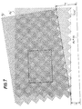
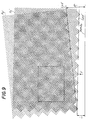
- Figs. 7, 9 and 11 show portions of the joined strip material produced with different inclinations of the directions of alignment Lx 3 and Lx 5 .
- the two directions Lx 3 and Lx 5 are inclined at 7° and 2° respectively
- Fig. 9 they are inclined at 6° and 1°
- Fig. 11 they are inclined at 4° and 1°.
- Figs. 8, 10 and 12 show enlargements of portions of Figs. 7, 9 and 11 in which, for the sake of simplicity, only the areas of contact between the two joined layers N3 and N5 are shown.
- the perimeters of the areas of contact between the two layers N3 and N5 are marked, while the protuberances which are not in contact with each other are not shown. The purpose of this is to show the arrangement of the areas of reciprocal contact between the two layers more clearly.
- Fig. 16 shows a portion of strip material produced by joining two layers embossed according to a different embodiment of the invention.
- Identical numbers indicate parts and elements which are identical or correspond to those shown in the proceeding figures.
- the directions of alignment Lx 3 ' and Lx 5 ' are inclined in the same direction with respect to the direction A5-A3 indicating the orientation of the axes of the cylinders 3 and 5.
- the angles ⁇ 3 and ⁇ 5 formed by the directions of alignment Lx 3 ' and Lx 5 ' with the direction of the axes of the cylinders are different from each other.
- This arrangement on the embossed layers corresponds to an arrangement on the embossing cylinders such that the directions of alignment Lx 3 and Lx 5 are inclined in opposite directions and with different angles with respect to the axes A 3 and A 5 .
- the two cylinders are provided with two spiral alignments, one with right-hand winding and the other with left-hand winding, and with two different angles.
- the two layers N 3 and N 5 are connected together only in certain areas, with only partial correspondence between the protuberances P 3 ' of one layer and the protuberances P 5 ' of the other layer.
- protuberances of truncated pyramidal form which are the most common. These are easily produced using simple machining processes, for example by chip-forming machining. In this case, the directions of alignment coincide with the directions of the diagonals of the quadrilateral bases of the truncated pyramids. However, different forms of protuberance are not excluded.
- the inclination characteristics described above of the directions of alignment of the protuberances may be uniform over the whole of the corresponding cylinder; in other words, the directions Lx 3 , Ly 3 , Lx 5 and Ly 5 may have the same inclination over the whole longitudinal development of the embossing cylinder 3 or 5 respectively.
- this is not essential, and the inclination of the directions of alignment may vary gradually along the axis of the cylinder, or may vary over successive sections of the cylinder.
- the two embossing cylinders 3, 5 are in contact with each other (with the interposition of the layers N3, N5) only at some of the protuberances along the tangency generatrices of the two cylinders, the specific pressure exerted at the said protuberances in contact is higher than that exerted between the opposing protuberances of a conventional tip-to-tip embossing machine, in which all the protuberances are in contact with each other. It is therefore extremely important to control the pressure between the rollers so as to avoid excessive crushing in the areas of reciprocal contact. For this purpose, it is possible, for example, for the two embossing cylinders 3, 5 to be thermostatically controlled.
- a system for controlling the pressure between the embossing cylinders 3, 5 which maintains this pressure at a constant level.
- This system is shown schematically in Fig. 1.
- the second embossing cylinder 5 and the second pressure roller 9 are carried by an oscillating moving element 16, pivoted at 16A on the structure of the machine and pressed by a cylinder and piston actuator 18 against a fixed stop 20.
- a movable and adjustable stop 22 carried by an extension 24 of the moving element 16 interacts with the fixed stop 20.
- the fixed stop is provided with a load cell which sends a signal proportional to the force exerted by the moving stop 22 to the control unit.
- the embossing cylinders 3, 5 are made with equal diameters and are connected together mechanically by a pair of gears with equal numbers of teeth, so that they have the same rotation speed. Since, with the protuberance arrangement according to the present invention, the reciprocal stresses are present in restricted areas of the embossing cylinders and always only in these areas, it is advantageous, in order to avoid concentrating the deformations as a result of the protuberances of the cylinders being crushed, to make the said cylinders with slightly different diameters.
- the embossing cylinders have diameters of 500/600 mm. With diameters of this order of magnitude it is possible to make two cylinders which have a difference of approximately 10/15 mm in their diameters.
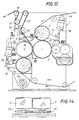
- Fig. 15 shows schematically a driving pulley 51 around which a belt 53 runs. This belt runs around further pulleys 55 and 57, keyed to the axles of the embossing cylinders 3 and 5 respectively, the path of the belt being such that the two cylinders rotate in opposite directions (in the example, the cylinder 3 rotates clockwise and the cylinder 5 rotates anti-clockwise).
- the number 59 indicates a tensioning jockey pulley which allows the two cylinders 3 and 5 to be moved apart and enables the gap between the cylinders to be adjusted.
- This type of transmission, or of another type which does not prevent the phase slip between the two cylinders 3 and 5 is also particularly advantageous by comparison with the conventional precision gear transmissions always used in tip-to-tip embossing machines because there is no need to reset the play between the gears or to lubricate them.
Landscapes
- Engineering & Computer Science (AREA)
- Mechanical Engineering (AREA)
- Machines For Manufacturing Corrugated Board In Mechanical Paper-Making Processes (AREA)
- Shaping Of Tube Ends By Bending Or Straightening (AREA)
- Laminated Bodies (AREA)
- Perforating, Stamping-Out Or Severing By Means Other Than Cutting (AREA)
- Credit Cards Or The Like (AREA)
- Lining Or Joining Of Plastics Or The Like (AREA)
Claims (18)
- Präge-und Kaschiermaschine mit einem ersten Prägezylinder (3) mit einer Fläche, die mit einer ersten Gruppe von Höckern (P3) versehen ist, welche in einem ersten Schrittabstand in einer ersten Ausricht-Richtung (Lx3) sind, sowie mit einem zweiten Schrittabstand in einer zweiten Ausricht-Richtung (Ly3) angeordnet sind, wobei die erste und die zweite Ausricht-Richtungen zwischen sich einen von Null verschiedenen Winkel (α) einschließen, mit einem zweiten Prägezylinder (5), dessen Achse (A5) sich parallel zur Achse (A3) des ersten Prägezylinder (3) erstreckt und mit dem ersten Prägezylinder (3) einen Kaschierspalt bildet und eine Fläche besitzt, die mit einer zweiten Gruppe von Höckern (P5) versehen ist, die mit dem erst: Schrittabstand in einer dritten Ausricht-Richtung (Lx5) und mit dem zweiten Schrittabstand in einer vierten Ausricht-Richtung (Ly5) angeordnet sind, wobei die dritte und die vierte Ausricht-Richtung zwischen sich einen Winkel einschließen, der ungefähr gleich dem Winkel (α) ist, den die erste und die zweite Ausricht-Richtung einschließen; sowie mit einer ersten und einer zweiten Druckrolle (7, 9), die beziehentlich mit dem ersten und dem zweiten Prägezylindern (3, 5) wechselwirken, und in welchem die Höcker längs Linien ausgerichtet sind, die bezüglich der Achsen des entsprechenden Zylinders (3,5) geneigt sind, dadurch gekennzeichnet, daß die erste und die dritte Ausricht-Richtung (Lx3, Lx5) eine Orientierung und Neigung bezüglich der Achse (A3, A5) des entsprechenden Zylinders derart besitzen, daß in dem Kaschierspalt die Höcker (P3) eines Prägezylinders (3) nur in bestimmten Bereichen mit den Höckern (P5) des anderen Prägezylinders (5) koinzidieren.
- Präge- und Kaschiermaschine nach Anspruch 1, dadurch gekennzeichnet, daß die erste Ausricht-Richtung (Lx3) und die dritte Ansricht-Richtung (Lx5) in der gleichen Richtung bezüglich der Achsen (A3, A5) der entsprechenden Prägezylinder (3, 5) geneigt sind.
- Präge- und Kashiermaschine nach Anspruch 2, dadurch gekennzeichnet, daß die beiden Prägezylinder (3, 5) identisch sind, wobei die erste und die dritte Ausricht-Richtung (Lx3, Lx5) die gleiche Neigung (β3 = β5) bezüglich der Achse (A3, A5) der entsprechenden Prägezylinder (3, 5) haben.
- Präge- und Kaschiermaschine nach Anspruch 1, dadurch gekennzeichnet, daß die erste und die dritte Ausricht-Richtung (Lx3, Lx5) zwei verschiedene Neigungen (β3, β5) bezüglich der Achse entsprechenden Prägezylinder (3, 5) haben.
- Präge- und Kaschiermaschine nach Anspruch 1, dadurch gekennzeichnet, daß die erste Ausricht-Richtung (Lx3) und die dritte Ausricht-Richtung (Lx5) in entgegengesetzte Richtungen bezüglich der Achse (A3, A5) der entsprechenden Zylinder (3, 5) geneigt sind und mit den Achsen zwei Winkel (β3, β5) bilden, die voneinander verschieden sind.
- Präge- und Kashiermaschine nach einem oder mehreren der vorstehenden Ansprüche, dadurch gekennzeichnet, daß die Höcker (P3, P5) der ersten und du zweiten Gruppe von Höckern die Form von Pydramidenstümpfen haben.
- Präge- und Kaschiermachine nach Anspruch 6, dadurch gekennzeichnet, daß die pyramidenstumpfförmigen Höcker einen rechteckigen Schnitt haben.
- Präge- und Kaschiermaschine nach Anspruch 7, dadurch gekennzeichnet, daß die erste und die zweite Ausricht-Richtung (Lx3, Ly5) sich Parallel zu den beiden Diagonalen der kleineren Basis jedes Höckers der ersten Gruppe von Höckern (P3) erstrecken, und daß sie dritten und die vierten Ausricht-Richtungen (Lx5, Ly5) sich parallel zu den beiden Diagonalen der kleineren Basis jedes Höckers der zweiten Gruppe von Höckern (P5) erstrecken.
- Präge- und Kaschiermaschine nach einem oder mehreren der vorstehenden Ansprüche, dadurch gekennzeichnet, daß die Höcker eine Dichte von zwischen 6 und 150 Höckern pro cm2 und vorzugsweise zwischen 10 und 60 Höckern pro cm2 besitzen.
- Präge- und Kaschiermaschine nach einem oder mehreren der vorstehenden Ansprüche, dadurch gekennzeichnet, daß die beiden Prägezylinder während ihres Betriebes auf einer überwachten Temperatur gehalten sind.
- Präge- und Kaschiermaschine nach einem oder mehreren der vorstehenden Ansprüche gekennzeichnet durch eine Kraftmeßdose (20), welche ein dem Druck zwischen den beiden Prägezylindern proportionales Signal aussendet, sowie durch ein Steuersystem, welches auf der Basis des Signals den Druck zwischen den Prägezylindern (3, 5) konstant hält.
- Präge- und Kaschiermaschine nach einem oder mehreren der vorstehenden Ansprüche, dadurch gekennzeichnet, daß die beiden Prägezylinder (3, 5) unterschiedliche Durchmesser haben und mit einem umfangsgeschwindigkeitsgleichen Modus angetrieben werden.
- Geprägtes Blatt mit wenigstens zwei Lagen (N3, N5), die separat geprägt und miteinander verklebt sind, wobei jede der beiden Lagen das gleiche Prägemuster aus mehreren Höckern aufweist, die in einem wiederholten geometrischen Muster in zwei Ausricht-Richtungen angeordnet sind, die zwischen sich einen von Null verschiedenen Winkel bilden, dadurch gekennzeichnet, daß die Ausricht-Richtungen (Lx3', Ly3') der Höcker (P3') der ersten Lage (N3) bezüglich den entsprechenden Ausricht-Richtungen (Lx5', Ly5',) der Höcker (P5') der zweiten Lage (N5) geneigt sind, wobei die Höcker (P3', P5') der ersten und der zweiten Lage (N3, N5) nur in einem beschränkten Bereich längs der Oberflächenentwicklung des Blattes (N2) miteinander in Kontakt stehen.
- Blatt nach Anspruch 13, dadurch gekennzeichnet, daß die Kontaktbereiche zwischen den Höckern der ersten Lage und den Höckern der zweiten Lage in zwei Richtungen ausgerichtet sind, die parallel bzw. senkrecht zu der Längsentwicklung des Blattes Weisen.
- Blatt nach Anspruch 13, dadurch gekennzeichnet, daß die Kontaktbereiche zwischend en Höckern der ersten Lage und den Höckern der leiten Lage in zwei Richtungen ausgerichtet sind, die bezüglich der Längsentwicklung des Blattes geneigt sind.
- Verfahren zum Prägen eines Materialstreifens, bei demeine erste endlose Lage (N3) durch Bildung einer ersten Gruppe von Höckern(P3) auf ihr geprägt wird, die mit zwei vorbestimmten Schrittabständen in einer ersten und einer zweiten Ausricht-Richtung (Lx3', Ly3') angeordnet sind,eine zweite endlose Lage (N5) separat von der ersten durch Bildung einer zweiten Gruppe von Höckern (P5') auf ihr geprägt wird, welche in den beiden vorbestimmten Schrittabständen in einer dritten und einer vierten Ausricht-Richtung (Lx5' Ly5')angeordnet sind,wobei die erste und die zweite Ausricht-Richtung zwischen sich einen von Null verschiedenen Winkel (α) einschließen, und die dritte und die vierte Ausricht-Richtung zwischen sich einen Winkel einschließen der etwa dem Winkel (α) gleich ist, der von der ersten und zweiten Richtung eingeschlossen wird;und die beiden Lagen (N3, N5) zur Bildung des Materialsstriefens (N2) verbunden werden.
dadurch gekennzeichnet, daß die erste (Lx3') und die dritte (Lx5') Ausricht-Richtung der Höcker (P3', P5') der ersten oder der zweiten Lage (N3, N5) in der Weise vorgesehen werden, daß dann, wenn die beiden Lagen verbunden sind, die erste und die dritte Ausricht-Richtung nicht parallel zueinander verlaufen und die Höcker der ersten Gruppe den Höckern der zweiten Gruppe nur in beschränkten Bereichen die Entwicklung des Streifenmaterials korrespondieren. - Verfahren nach Anspruch 16, dadurch gekennzeichnet, daß die erste und die dritte Ausricht-Richtung (Lx3', Lx5') zwei gleiche Winkel mit der Vorschubrichtung des Streifenmaterials bilden, wobei die Bereiche, in denen die Höcker du ersten und der zweiten Gruppe koinzidieren, in zwei Richtungen ausgerichtet werden, die parallel bzw. senkrecht zur Vorschubrichtung des Streifenmaterials sind.
- Verfahren nach Anspruch 16, dadurch gekennzeichnet, daß die erste und die dritte Ausricht-Richtung (Lx3', Lx5') zwei verschiedene Winkel mit der Vorschubrichtung des Streifenmaterials bilden, wobei die Bereiche, in denen die Höcker der ersten und der zweiten Gruppe koinzidieren, in zwei Richtungen ausgerichtet sind, die bezüglich der Vorschubrichtung des Streifenmaterials geneigt sind.
Applications Claiming Priority (3)
| Application Number | Priority Date | Filing Date | Title |
|---|---|---|---|
| IT95FI000247A IT1278801B1 (it) | 1995-12-05 | 1995-12-05 | Gruppo goffratore-laminatore per l'incollaggio dei veli goffrati, relativo metodo e prodotto ottenuto |
| ITFI950247 | 1995-12-05 | ||
| PCT/IT1996/000239 WO1997020688A1 (en) | 1995-12-05 | 1996-12-02 | Embossing and laminating machine for gluing embossed layers |
Publications (2)
| Publication Number | Publication Date |
|---|---|
| EP0868302A1 EP0868302A1 (de) | 1998-10-07 |
| EP0868302B1 true EP0868302B1 (de) | 1999-11-17 |
Family
ID=11351427
Family Applications (1)
| Application Number | Title | Priority Date | Filing Date |
|---|---|---|---|
| EP96941808A Expired - Lifetime EP0868302B1 (de) | 1995-12-05 | 1996-12-02 | Präge-und kaschiermaschine zum verkleben von geprägten schichten |
Country Status (17)
| Country | Link |
|---|---|
| US (1) | US6245414B1 (de) |
| EP (1) | EP0868302B1 (de) |
| JP (1) | JP2000501349A (de) |
| KR (1) | KR19990071937A (de) |
| CN (1) | CN1203550A (de) |
| AT (1) | ATE186674T1 (de) |
| AU (1) | AU1108497A (de) |
| BR (1) | BR9611687A (de) |
| CA (1) | CA2239435A1 (de) |
| DE (1) | DE69605210T2 (de) |
| ES (1) | ES2138392T3 (de) |
| GR (1) | GR3032079T3 (de) |
| IL (1) | IL124774A (de) |
| IT (1) | IT1278801B1 (de) |
| PL (1) | PL327080A1 (de) |
| RU (1) | RU2162414C2 (de) |
| WO (1) | WO1997020688A1 (de) |
Families Citing this family (56)
| Publication number | Priority date | Publication date | Assignee | Title |
|---|---|---|---|---|
| WO1999044814A1 (en) | 1998-03-02 | 1999-09-10 | Fabio Perini S.P.A. | Method and device for producing an embossed web material and product made in this way |
| AU3721599A (en) * | 1998-08-10 | 2000-03-06 | Hunt Technology Limited | Improvements relating to methods of thermal lamination |
| US6251207B1 (en) * | 1998-12-31 | 2001-06-26 | Kimberly-Clark Worldwide, Inc. | Embossing and laminating irregular bonding patterns |
| IT1307887B1 (it) | 1999-06-18 | 2001-11-19 | Perini Fabio Spa | Metodo e dispositivo di goffratura per la produzione di materialenastriforme multivelo, e prodotto cosi' ottenuto. |
| DE10043984A1 (de) * | 1999-09-08 | 2001-03-22 | A & E Ungricht Gmbh & Co Kg | Verfahren zum Verbinden eines Endabschnittes einer nahezu abgearbeiteten Papier-Zufuhrrolle mit dem Anfangsabschnitt einer weiteren Zufuhrrolle sowie Prägewalzenpaar zur Durchführung des Verfahrens |
| RU2160187C1 (ru) * | 1999-10-28 | 2000-12-10 | Александр Леонидович Хомич | Лотерейный билет |
| ATE364751T1 (de) * | 2001-03-09 | 2007-07-15 | Georgia Pacific France | Papierbahn mit kleinen kissen |
| ATE353993T1 (de) * | 2001-12-27 | 2007-03-15 | Georgia Pacific France | Geprägte papierbahn |
| ITFI20020053A1 (it) | 2002-03-29 | 2003-09-29 | Perini Fabio Spa | Metodo e dispositivo per la produzione di un materiale nastriforme goffrato e manufatto ottenuto con detto metodo |
| US8118584B2 (en) * | 2002-06-25 | 2012-02-21 | Sumitomo Bakelite Company Limited | Device and method for processing carrier tape |
| ITFI20020113A1 (it) * | 2002-06-26 | 2003-12-29 | Perini Fabio Spa | Dispositivo goffratore e laminatore con gruppo di cilindri goffratoriintercambiabile |
| US20040166290A1 (en) * | 2002-12-09 | 2004-08-26 | Sca Hygiene Products Gmbh | Process for laminating plies of tissue paper and laminated tissue paper |
| EP1428654A1 (de) * | 2002-12-09 | 2004-06-16 | SCA Hygiene Products GmbH | Verfahren zur Herstellung von mehrlagigen Tissuepapieren und mehrlagige Tissuepapiere |
| US20040191486A1 (en) * | 2003-03-25 | 2004-09-30 | Underhill Richard Louis | Cloth-like tissue sheets having camouflaged texture |
| USD688466S1 (en) * | 2003-10-16 | 2013-08-27 | The Procter & Gamble Company | Paper product with surface pattern |
| USD688878S1 (en) * | 2003-10-16 | 2013-09-03 | The Procter & Gamble Company | Paper product with surface pattern |
| USD494766S1 (en) | 2003-10-30 | 2004-08-24 | Potlatch Corporation | Surface pattern for a paper towel |
| USD496797S1 (en) | 2003-10-30 | 2004-10-05 | Potlatch Corporation | Surface pattern for a paper towel |
| USD502004S1 (en) * | 2003-11-12 | 2005-02-22 | Fort James Corporation | Paper product |
| USD505551S1 (en) * | 2003-11-12 | 2005-05-31 | Fort James Corporation | Paper product |
| USD504779S1 (en) * | 2003-11-12 | 2005-05-10 | Fort James Corporation | Paper product |
| USD527909S1 (en) * | 2003-11-12 | 2006-09-12 | Fort James Corporation | Paper product |
| USD504573S1 (en) * | 2003-11-12 | 2005-05-03 | Fort James Corporation | Paper product |
| USD504236S1 (en) * | 2003-11-12 | 2005-04-26 | Fort James Corporation | Paper product |
| DE202004013598U1 (de) * | 2004-08-31 | 2004-12-23 | Sca Hygiene Products Ab | Papierprodukt und Vorrichtung zum Prägen einer Papierbahn |
| US7012232B1 (en) | 2004-08-31 | 2006-03-14 | Mark Gruenspecht | RF welding device |
| EP1712667B1 (de) * | 2005-04-11 | 2011-01-05 | Pantex International S.p.A. | Verfahren zur Herstellung einer Faservlies sowie danach hergestelltes Produkt |
| DE102006010709A1 (de) * | 2006-03-08 | 2007-09-13 | Metsä Tissue Oyj | Prägevorrichtung für mindestens zweilagige Flächenprodukte wie Toilettenpapier, Taschentücher o. dgl. |
| ITFI20060072A1 (it) * | 2006-03-15 | 2007-09-16 | Perini Fabio Spa | Rullo goffratore e relativo procedimento per la sua produzione |
| FR2899502B1 (fr) * | 2006-04-06 | 2009-04-10 | Macdermid Printing Solutions E | Dispositif de gaufrage, tel qu'un cylindre ou manchon |
| ITFI20060245A1 (it) | 2006-10-11 | 2008-04-12 | Delicarta Spa | Un materiale in carta con elevate caratteristiche detergenti e metodo per la sua produzione |
| ITFI20070048A1 (it) * | 2007-02-27 | 2008-08-28 | Perini Fabio Spa | Gruppo goffratore multi-funzione |
| MY157691A (en) * | 2007-04-05 | 2016-07-15 | Imp Tobacco Canada Ltd | Apparatus and method for producing embossed paper or laminated metallic foil sheets |
| ITFI20070163A1 (it) | 2007-07-18 | 2009-01-19 | Perini Fabio Spa | "materiale cartaceo goffrato, metodo e dispositivo per la sua produzione" |
| ITFI20080038A1 (it) | 2008-02-27 | 2009-08-28 | Delicarta Spa | "materiale plurivelo in carta goffrata e macchina per la sua produzione" |
| JP2012040775A (ja) * | 2010-08-19 | 2012-03-01 | Oji Nepia Co Ltd | ロール状衛生用紙の製造方法 |
| US8791321B2 (en) | 2010-08-26 | 2014-07-29 | Medline Industries, Inc. | Disposable absorbent lift device |
| CN102407614B (zh) * | 2011-11-14 | 2013-09-18 | 佛山市南海区德昌誉机械制造有限公司 | 一种纸巾加工设备上用的压花装置及其压花生产工艺 |
| USD840163S1 (en) * | 2014-05-16 | 2019-02-12 | Gpcp Ip Holdings Llc | Paper product |
| US9915034B2 (en) | 2014-05-16 | 2018-03-13 | Gpcp Ip Holdings Llc | High bulk tissue product |
| PT3194154T (pt) | 2014-08-29 | 2018-11-07 | Sofidel Spa | Produto de celulose em relevo em várias camadas e meios para a sua produção |
| GB201415748D0 (en) | 2014-09-05 | 2014-10-22 | Hadley Ind Overseas Holdings Ltd | Sheet material forming |
| RU2019126804A (ru) | 2014-09-05 | 2019-09-10 | Хэдли Индастриз Оверсиз Холдингз Лтд. | Профили |
| DE102015204265B4 (de) | 2015-03-10 | 2024-08-01 | Continental Reifen Deutschland Gmbh | Vorrichtung zum beidseitigen Belegen von Festigkeitsträgern mit Gummimischungsbahnen |
| CN106031602B (zh) * | 2015-03-17 | 2020-07-17 | 金红叶纸业集团有限公司 | 一种生活用纸及其制作方法 |
| US11337566B2 (en) * | 2017-06-30 | 2022-05-24 | Daio Paper Corporation | Toilet paper |
| CN110215148A (zh) * | 2018-03-01 | 2019-09-10 | 王子控股株式会社 | 薄纸及薄纸用的压花加工装置 |
| BR112020022071A2 (pt) * | 2018-05-29 | 2021-02-02 | José Antonio Logiodice | aperfeiçoamento em conjunto gofrador para processamento de papel |
| USD906692S1 (en) * | 2018-09-13 | 2021-01-05 | Fitesa Germany Gmbh | Sheet material |
| US11654650B2 (en) * | 2019-06-05 | 2023-05-23 | GAMBINI S.p.A. | Embossing and lamination assembly and relative embossing and lamination method |
| US11702797B2 (en) | 2020-03-16 | 2023-07-18 | Gpcp Ip Holdings Llc | Tissue products formed from multi-apex emboss elements and methods for producing the same |
| US11441274B2 (en) | 2020-03-16 | 2022-09-13 | Gpcp Ip Holdings Llc | Tissue products having emboss elements with reduced bunching and methods for producing the same |
| RU2757440C1 (ru) * | 2020-04-03 | 2021-10-15 | Елена Анатольевна Пыжова | Способ и устройство тиснения листовых или рулонных материалов и изделие, полученное указанным способом |
| IT202200003380A1 (it) | 2022-02-23 | 2023-08-23 | Engraving Solutions S R L | Rullo goffratore, metodo di incisione e goffratore comprendente il rullo goffratore |
| IT202200006239A1 (it) * | 2022-03-30 | 2023-09-30 | Valmet Tissue Converting S P A | Dispositivo goffratore-laminatore e metodo |
| WO2024148407A1 (pt) | 2023-01-11 | 2024-07-18 | Roll-Tec Cilindro Ltda | Conjunto para gofragem progressiva de folhas de papel |
Family Cites Families (5)
| Publication number | Priority date | Publication date | Assignee | Title |
|---|---|---|---|---|
| US3414459A (en) | 1965-02-01 | 1968-12-03 | Procter & Gamble | Compressible laminated paper structure |
| US3961119A (en) | 1973-03-15 | 1976-06-01 | Kimberly-Clark Corporation | Embossed paper toweling and method of production |
| IT1225324B (it) * | 1988-11-23 | 1990-11-06 | Perini Finanziaria Spa | Macchina per la trasformazione della carta con cilindri goffratori cooperanti per l'accoppiamento punta-punta di due nastri di carta da essi goffrati |
| FR2653793B1 (de) * | 1989-10-30 | 1992-01-03 | Kaysersberg Sa | |
| FR2689149B1 (fr) * | 1992-03-31 | 1994-05-13 | Kaysersberg | Nouveaux papiers gaufres multicouches. dispositif et procede pour leur elaboration. |
-
1995
- 1995-12-05 IT IT95FI000247A patent/IT1278801B1/it active IP Right Grant
-
1996
- 1996-12-02 EP EP96941808A patent/EP0868302B1/de not_active Expired - Lifetime
- 1996-12-02 WO PCT/IT1996/000239 patent/WO1997020688A1/en not_active Ceased
- 1996-12-02 US US09/077,229 patent/US6245414B1/en not_active Expired - Fee Related
- 1996-12-02 CN CN96198865A patent/CN1203550A/zh active Pending
- 1996-12-02 PL PL96327080A patent/PL327080A1/xx unknown
- 1996-12-02 AU AU11084/97A patent/AU1108497A/en not_active Abandoned
- 1996-12-02 IL IL12477496A patent/IL124774A/en not_active IP Right Cessation
- 1996-12-02 RU RU98112268/12A patent/RU2162414C2/ru active
- 1996-12-02 ES ES96941808T patent/ES2138392T3/es not_active Expired - Lifetime
- 1996-12-02 AT AT96941808T patent/ATE186674T1/de active
- 1996-12-02 KR KR1019980704224A patent/KR19990071937A/ko not_active Abandoned
- 1996-12-02 CA CA002239435A patent/CA2239435A1/en not_active Abandoned
- 1996-12-02 DE DE69605210T patent/DE69605210T2/de not_active Expired - Fee Related
- 1996-12-02 JP JP9521135A patent/JP2000501349A/ja not_active Ceased
- 1996-12-02 BR BR9611687A patent/BR9611687A/pt not_active IP Right Cessation
-
1999
- 1999-12-08 GR GR990403170T patent/GR3032079T3/el unknown
Also Published As
| Publication number | Publication date |
|---|---|
| IL124774A0 (en) | 1999-01-26 |
| EP0868302A1 (de) | 1998-10-07 |
| ITFI950247A1 (it) | 1997-06-05 |
| BR9611687A (pt) | 1999-03-02 |
| GR3032079T3 (en) | 2000-03-31 |
| ES2138392T3 (es) | 2000-01-01 |
| JP2000501349A (ja) | 2000-02-08 |
| IT1278801B1 (it) | 1997-11-28 |
| IL124774A (en) | 2001-05-20 |
| DE69605210T2 (de) | 2000-07-13 |
| CA2239435A1 (en) | 1997-06-12 |
| CN1203550A (zh) | 1998-12-30 |
| RU2162414C2 (ru) | 2001-01-27 |
| US6245414B1 (en) | 2001-06-12 |
| ITFI950247A0 (de) | 1995-12-05 |
| ATE186674T1 (de) | 1999-12-15 |
| DE69605210D1 (de) | 1999-12-23 |
| AU1108497A (en) | 1997-06-27 |
| KR19990071937A (ko) | 1999-09-27 |
| WO1997020688A1 (en) | 1997-06-12 |
| PL327080A1 (en) | 1998-11-23 |
Similar Documents
| Publication | Publication Date | Title |
|---|---|---|
| EP0868302B1 (de) | Präge-und kaschiermaschine zum verkleben von geprägten schichten | |
| EP0868303B1 (de) | Präge und kaschiermaschine mit prägezylindern die verteilte kontaktflächen aufweisen | |
| EP0868301B1 (de) | Präge-und kaschiermaschine mit zwei prägezylindern unterschiedlicher umlaufgeschwindigkeit | |
| CA2200254C (en) | Method of producing lamented embossed webs having equal embossed definition on both sides | |
| US6863107B2 (en) | Device for applying a spot embossing pattern to a web of multi-ply tissue paper | |
| KR100399866B1 (ko) | 2개이상의 플라이로 이루어진 웨브재료를 엠보싱 및 적층하는 장치 | |
| EP1434687B1 (de) | Verfahren und vorrichtung zum prägen einer mehrlagigen tissue-papierbahn | |
| US20030110961A1 (en) | Embossing device | |
| HK1017311A (en) | Embossing and laminating machine with embossing cylinders having different rotational speed | |
| HK1017309A (en) | Embossing and laminating machine for gluing embossed layers | |
| HK1017310A (en) | Embossing and laminating machine and method with cylinders with distributed contact areas | |
| GB2308392A (en) | Single-faced corrugated cardboard sheet making machine |
Legal Events
| Date | Code | Title | Description |
|---|---|---|---|
| PUAI | Public reference made under article 153(3) epc to a published international application that has entered the european phase |
Free format text: ORIGINAL CODE: 0009012 |
|
| 17P | Request for examination filed |
Effective date: 19980615 |
|
| AK | Designated contracting states |
Kind code of ref document: A1 Designated state(s): AT CH DE ES FI FR GB GR LI NL SE |
|
| GRAG | Despatch of communication of intention to grant |
Free format text: ORIGINAL CODE: EPIDOS AGRA |
|
| 17Q | First examination report despatched |
Effective date: 19990304 |
|
| GRAG | Despatch of communication of intention to grant |
Free format text: ORIGINAL CODE: EPIDOS AGRA |
|
| GRAH | Despatch of communication of intention to grant a patent |
Free format text: ORIGINAL CODE: EPIDOS IGRA |
|
| GRAH | Despatch of communication of intention to grant a patent |
Free format text: ORIGINAL CODE: EPIDOS IGRA |
|
| GRAA | (expected) grant |
Free format text: ORIGINAL CODE: 0009210 |
|
| AK | Designated contracting states |
Kind code of ref document: B1 Designated state(s): AT CH DE ES FI FR GB GR LI NL SE |
|
| REF | Corresponds to: |
Ref document number: 186674 Country of ref document: AT Date of ref document: 19991215 Kind code of ref document: T |
|
| REG | Reference to a national code |
Ref country code: CH Ref legal event code: NV Representative=s name: BOVARD AG PATENTANWAELTE Ref country code: CH Ref legal event code: EP |
|
| REF | Corresponds to: |
Ref document number: 69605210 Country of ref document: DE Date of ref document: 19991223 |
|
| REG | Reference to a national code |
Ref country code: ES Ref legal event code: FG2A Ref document number: 2138392 Country of ref document: ES Kind code of ref document: T3 |
|
| ET | Fr: translation filed | ||
| PLBE | No opposition filed within time limit |
Free format text: ORIGINAL CODE: 0009261 |
|
| STAA | Information on the status of an ep patent application or granted ep patent |
Free format text: STATUS: NO OPPOSITION FILED WITHIN TIME LIMIT |
|
| 26N | No opposition filed | ||
| PGFP | Annual fee paid to national office [announced via postgrant information from national office to epo] |
Ref country code: SE Payment date: 20001108 Year of fee payment: 5 |
|
| PGFP | Annual fee paid to national office [announced via postgrant information from national office to epo] |
Ref country code: GR Payment date: 20001130 Year of fee payment: 5 |
|
| PGFP | Annual fee paid to national office [announced via postgrant information from national office to epo] |
Ref country code: CH Payment date: 20001207 Year of fee payment: 5 |
|
| PGFP | Annual fee paid to national office [announced via postgrant information from national office to epo] |
Ref country code: FI Payment date: 20001222 Year of fee payment: 5 |
|
| PGFP | Annual fee paid to national office [announced via postgrant information from national office to epo] |
Ref country code: AT Payment date: 20001229 Year of fee payment: 5 |
|
| PGFP | Annual fee paid to national office [announced via postgrant information from national office to epo] |
Ref country code: NL Payment date: 20001231 Year of fee payment: 5 |
|
| PG25 | Lapsed in a contracting state [announced via postgrant information from national office to epo] |
Ref country code: FI Free format text: LAPSE BECAUSE OF NON-PAYMENT OF DUE FEES Effective date: 20011202 Ref country code: AT Free format text: LAPSE BECAUSE OF NON-PAYMENT OF DUE FEES Effective date: 20011202 |
|
| PG25 | Lapsed in a contracting state [announced via postgrant information from national office to epo] |
Ref country code: SE Free format text: LAPSE BECAUSE OF NON-PAYMENT OF DUE FEES Effective date: 20011203 |
|
| PG25 | Lapsed in a contracting state [announced via postgrant information from national office to epo] |
Ref country code: LI Free format text: LAPSE BECAUSE OF NON-PAYMENT OF DUE FEES Effective date: 20011231 Ref country code: CH Free format text: LAPSE BECAUSE OF NON-PAYMENT OF DUE FEES Effective date: 20011231 |
|
| REG | Reference to a national code |
Ref country code: GB Ref legal event code: IF02 |
|
| PG25 | Lapsed in a contracting state [announced via postgrant information from national office to epo] |
Ref country code: NL Free format text: LAPSE BECAUSE OF NON-PAYMENT OF DUE FEES Effective date: 20020701 |
|
| PG25 | Lapsed in a contracting state [announced via postgrant information from national office to epo] |
Ref country code: GR Free format text: LAPSE BECAUSE OF NON-PAYMENT OF DUE FEES Effective date: 20020708 |
|
| EUG | Se: european patent has lapsed |
Ref document number: 96941808.6 |
|
| REG | Reference to a national code |
Ref country code: CH Ref legal event code: PL |
|
| NLV4 | Nl: lapsed or anulled due to non-payment of the annual fee |
Effective date: 20020701 |
|
| PGFP | Annual fee paid to national office [announced via postgrant information from national office to epo] |
Ref country code: ES Payment date: 20051121 Year of fee payment: 10 |
|
| PGFP | Annual fee paid to national office [announced via postgrant information from national office to epo] |
Ref country code: GB Payment date: 20051130 Year of fee payment: 10 |
|
| PGFP | Annual fee paid to national office [announced via postgrant information from national office to epo] |
Ref country code: FR Payment date: 20051216 Year of fee payment: 10 |
|
| PGFP | Annual fee paid to national office [announced via postgrant information from national office to epo] |
Ref country code: DE Payment date: 20051227 Year of fee payment: 10 |
|
| PG25 | Lapsed in a contracting state [announced via postgrant information from national office to epo] |
Ref country code: DE Free format text: LAPSE BECAUSE OF NON-PAYMENT OF DUE FEES Effective date: 20070703 |
|
| GBPC | Gb: european patent ceased through non-payment of renewal fee |
Effective date: 20061202 |
|
| REG | Reference to a national code |
Ref country code: FR Ref legal event code: ST Effective date: 20070831 |
|
| PG25 | Lapsed in a contracting state [announced via postgrant information from national office to epo] |
Ref country code: GB Free format text: LAPSE BECAUSE OF NON-PAYMENT OF DUE FEES Effective date: 20061202 |
|
| REG | Reference to a national code |
Ref country code: ES Ref legal event code: FD2A Effective date: 20061204 |
|
| PG25 | Lapsed in a contracting state [announced via postgrant information from national office to epo] |
Ref country code: FR Free format text: LAPSE BECAUSE OF NON-PAYMENT OF DUE FEES Effective date: 20070102 Ref country code: ES Free format text: LAPSE BECAUSE OF NON-PAYMENT OF DUE FEES Effective date: 20061204 |