EP0868600B1 - Dispositif de regulation de la force de frein-moteur dans un moteur a combustion interne - Google Patents
Dispositif de regulation de la force de frein-moteur dans un moteur a combustion interne Download PDFInfo
- Publication number
- EP0868600B1 EP0868600B1 EP96943463A EP96943463A EP0868600B1 EP 0868600 B1 EP0868600 B1 EP 0868600B1 EP 96943463 A EP96943463 A EP 96943463A EP 96943463 A EP96943463 A EP 96943463A EP 0868600 B1 EP0868600 B1 EP 0868600B1
- Authority
- EP
- European Patent Office
- Prior art keywords
- valve
- exhaust
- cylinder
- piston
- engine
- Prior art date
- Legal status (The legal status is an assumption and is not a legal conclusion. Google has not performed a legal analysis and makes no representation as to the accuracy of the status listed.)
- Expired - Lifetime
Links
Images



Classifications
-
- F—MECHANICAL ENGINEERING; LIGHTING; HEATING; WEAPONS; BLASTING
- F02—COMBUSTION ENGINES; HOT-GAS OR COMBUSTION-PRODUCT ENGINE PLANTS
- F02B—INTERNAL-COMBUSTION PISTON ENGINES; COMBUSTION ENGINES IN GENERAL
- F02B37/00—Engines characterised by provision of pumps driven at least for part of the time by exhaust
- F02B37/005—Exhaust driven pumps being combined with an exhaust driven auxiliary apparatus, e.g. a ventilator
-
- F—MECHANICAL ENGINEERING; LIGHTING; HEATING; WEAPONS; BLASTING
- F02—COMBUSTION ENGINES; HOT-GAS OR COMBUSTION-PRODUCT ENGINE PLANTS
- F02D—CONTROLLING COMBUSTION ENGINES
- F02D13/00—Controlling the engine output power by varying inlet or exhaust valve operating characteristics, e.g. timing
- F02D13/02—Controlling the engine output power by varying inlet or exhaust valve operating characteristics, e.g. timing during engine operation
- F02D13/04—Controlling the engine output power by varying inlet or exhaust valve operating characteristics, e.g. timing during engine operation using engine as brake
-
- F—MECHANICAL ENGINEERING; LIGHTING; HEATING; WEAPONS; BLASTING
- F02—COMBUSTION ENGINES; HOT-GAS OR COMBUSTION-PRODUCT ENGINE PLANTS
- F02D—CONTROLLING COMBUSTION ENGINES
- F02D9/00—Controlling engines by throttling air or fuel-and-air induction conduits or exhaust conduits
- F02D9/04—Controlling engines by throttling air or fuel-and-air induction conduits or exhaust conduits concerning exhaust conduits
- F02D9/06—Exhaust brakes
-
- F—MECHANICAL ENGINEERING; LIGHTING; HEATING; WEAPONS; BLASTING
- F02—COMBUSTION ENGINES; HOT-GAS OR COMBUSTION-PRODUCT ENGINE PLANTS
- F02D—CONTROLLING COMBUSTION ENGINES
- F02D9/00—Controlling engines by throttling air or fuel-and-air induction conduits or exhaust conduits
- F02D9/08—Throttle valves specially adapted therefor; Arrangements of such valves in conduits
- F02D9/12—Throttle valves specially adapted therefor; Arrangements of such valves in conduits having slidably-mounted valve members; having valve members movable longitudinally of conduit
- F02D9/14—Throttle valves specially adapted therefor; Arrangements of such valves in conduits having slidably-mounted valve members; having valve members movable longitudinally of conduit the members being slidable transversely of conduit
-
- Y—GENERAL TAGGING OF NEW TECHNOLOGICAL DEVELOPMENTS; GENERAL TAGGING OF CROSS-SECTIONAL TECHNOLOGIES SPANNING OVER SEVERAL SECTIONS OF THE IPC; TECHNICAL SUBJECTS COVERED BY FORMER USPC CROSS-REFERENCE ART COLLECTIONS [XRACs] AND DIGESTS
- Y02—TECHNOLOGIES OR APPLICATIONS FOR MITIGATION OR ADAPTATION AGAINST CLIMATE CHANGE
- Y02T—CLIMATE CHANGE MITIGATION TECHNOLOGIES RELATED TO TRANSPORTATION
- Y02T10/00—Road transport of goods or passengers
- Y02T10/10—Internal combustion engine [ICE] based vehicles
- Y02T10/12—Improving ICE efficiencies
Definitions
- the present invention relates to a six cylinder engine according to the preamble of claim 1.
- the engine braking power of a vehicle can be increased with the aid of a device of the above described type, by means of which the engine combustion chambers in brake mode during the latter portion of the compression stroke is connected to the exhaust system, for example by opening the regular exhaust valve.
- the result will be that the air compressed during the compression stroke flows out of the cylinders and that the compression work carried out during the compression stroke will not be recovered during the expansion stroke, and this will result in an increase in the engine braking power.
- An additional increase in the braking power can be achieved in this case in a known manner by connecting the exhaust system to the cylinders during the latter portion of the induction stroke, so that gas from the exhaust system can flow into the cylinders. This results in an increase in pressure in the cylinder and an inner charging so that the compression work after breaking off the communication between the cylinders and the exhaust system will be increased.
- EP 0 467 423 discloses a six cylinder engine having two exhaust manifolds for each three cylinders and a turbo compressor installation comprising a small capacity quick response compressor and a large capacity slower response compressor. There are two valves between the exhaust manifold and the turbine of the large capacity compressor. In one operating condition the valves are closed so that all exhaust gas passes through the turbine of the small capacity compressor. These valves, however, are not adapted to control the braking effect of the engine.
- said valve means are formed of an exhaust pressure regulator (EP regulator), i.e. a damper in the exhaust line downstream of the turbine portion of the turbocompressor unit.
- EP regulator exhaust pressure regulator
- the damper is controlled by a control unit into which the driver feeds a desired value of the vehicle retardation and into which engine data is fed via sensors such as the degree of charge and the rpm, and vehicle data such as vehicle speed, accelerator position and clutch pedal position.
- the purpose of the present invention is in general to achieve a device of the type described by way of introduction which makes it possible to achieve higher braking power in the engine than what could be achieved with the device described in SE-A-9401059.
- the particular purpose is to achieve a device in which the turbocompressor unit can be utilized in a better manner together with the valve means in the exhaust line to vary the braking power of the engine.
- valve means By placing the valve means closer to the exhaust outlet from the cylinders, there is a reduction in the volume of the exhaust conduit between the exhaust valves and the valve means in the exhaust conduit, which means that the pistons will not need to exhaust as much gas as previously in order to create a certain counter-pressure. High counter-pressure can therefore be obtained more rapidly.
- the turbocompressor unit can provide supercharging even in brake mode. It is true that the pistons are imparted energy from the gas during the induction stroke, but the work which the pistons must carry out against the gas during the compression stroke will be so much greater that the net effect will be a higher braking power.
- Another advantage of circulating large volumes of gas through the engine in brake mode is that a greater amount of heat will be removed through the gas than in installations with exhaust pressure regulators in which the heat is primarily diverted by cooling water.
- the turbine portion in a turbocompressor unit which is dimensioned to operate in drive mode within the normal rpm range of the engine, will be too large to be able to supercharge in brake mode.
- the device according to the invention is therefore regularly suited to be used in turbocharged engines with turbines which have variable geometry, or in so-called turbocompound engines which have a turbocompressor unit with a first turbine stage. which drives the compressor portion, and a second turbine stage, which is coupled, via a transmission. to the engine crankshaft.
- the first turbine stage is a small high-pressure turbine.
- the second turbine stage is a larger low-pressure turbine. It has been found that the corrected mass flow to the compressor turbine in brake mode is approximately equal to that for turbocompound engine mode.
- the compressor turbine is substantially larger, which means that the corrected massflows in brake mode and drive mode will approximately equal first at engine rpm:s above the normal operating rpm.
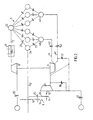
- Figure 1 shows schematically a turbocompound engine with a device according to the invention.
- Figure 2 a simplified schematic representation of the engine in Fig 1
- Figure 3 a simplified schematic representation of a turbocharged engine with a turbine with variable geometry and with a device according to the invention
- Figure 4 a schematic representation of a rurbocompound engine with a device according to the invention in a third embodiment
- Figure 5 a simplified schematic representation of the engine in Fig 4
- Figure 6 a longitudinal section through an exhaust restrictor valve according to the invention
- Figure 7 a longitudinal section through a combined restrictor and venting valve on the intake side.
- Fig 1, 1 designates a six cylinder engine with a gearbox 2 attached thereto
- a turbocompressor unit generally designated 3. has a first turbine stage 4 and a second turbine stage 5 connected to the engine exhaust manifold 6.
- the first turbine stage 4 is a small high-pressure stage, which drives a compressor 8 connected to the engine intake conduit 7, while the second turbine stage 5 is a larger low-pressure stage, which is coupled via a transmission 9 to the engine crankshaft 10.
- the transmission 9 comprises a gear 11 on the output shaft 12 of the turbine stage 5. said shaft 12 driving, via a pair of gears 13.14 on an intermediate shaft 15 a gear 16 on the crankshaft 10 (see Fig 2).
- Via a first continuously adjustable waste-gate valve 17 a larger or smaller amount of exhaust can be shunted past the high-pressure turbine 4 in order to vary the degree of charge.
- the engine 1 Via a second shunt valve 18. the exhaust can be shunted past the low-pressure turbine 5.
- the engine 1 has a schematically indicated compression braking device 19. which can be of the type which is shown and described in SE-466 320. and by means of which the engine cylinders during the latter portion of induction stroke, as well as during the latter portion of the compression stroke, can be connected to the engine exhaust manifold to increase the engine braking power.
- a schematically indicated compression braking device 19 which can be of the type which is shown and described in SE-466 320. and by means of which the engine cylinders during the latter portion of induction stroke, as well as during the latter portion of the compression stroke, can be connected to the engine exhaust manifold to increase the engine braking power.
- Fig 2 shows schematically a few details which are not apparent from Fig 1, viz. an air filter 20. a charged air cooler 21, an intake manifold 22. intake valves 23, cylinders 24, exhaust valves 25 and a muffler 27.
- Fig 3 shows an engine installation differing from that described above by virtue of the fact that the turbocompound unit has been replaced by a turbocompressor unit with a turbine portion 30. which has continuously variable geometry. Details corresponding to those in Fig 2 have been given the same reference numerals in Fig 3 as in Fig 2.
- Figs 4 and 5 show an engine installation differing from that in Figs 1 and 2 by virtue of the fact that the waste-gate valve 17 on the exhaust side has been eliminated and been replaced by a combined restrictor and venting valve 80 in the induction conduit 7 on the pressure side of the compressor 8.
- the valve 80 is shown in more detail in Fig 7. Parts corresponding to those in Figs 1 and 2 have been given the same reference numerals in Figs 4 and 5 as in Figs 1 and 2.
- the valve 80 has a housing 81 made in one piece with the engine induction conduit 7 with a cylinder 82. in which a piston 83 is axially displaceable.
- the piston has a through-bore 84 and is biased by a spring 85 towards the open position shown in Fig 7, in which air in the induction conduit can flow through the bore 84 to the engine cylinders.
- pressure medium is introduced to the cylinder chamber 85 to the left of the piston 83. and the piston is thus displaced to the right in Fig 7 so that the piston portion 87 to the left of the bore 84 is displaced into the induction conduit 7 and reduces its flow-through area.
- valve 80 on the induction side operates in a cleaner environment than a waste-gate valve on the exhaust side and is also subjected to substantially lower thermal load than the latter.
- the valve 80 is of particularly simple construction by virtue of the fact that it only has a single moving part. i.e. the piston 83. which functions both as a restrictor in the induction conduit and as a valve element for the venting opening 89.
- the manifold 6, as is most clearly illustrated in Figs 2 and 3. is divided into two submanifolds 40, the output exhaust conduits 41 of which meet in a contluence before the inlet to the turbocompressor unit 3 resp 30.
- a restrictor valve 42 is disposed in accordance with the invention, each valve having a completely open position and a restrictor position in which the flow-through area of the conduit 41 is reduced to create an exhaust counter-pressure in the exhaust manifold 6 during engine braking.
- a valve 42 which is to function in the environment of an exhaust manifold, must be able to withstand high mechanical and thermal stresses. In the open position it must not present any flow obstacles or create turbulence in the exhaust conduit valve 42 which fulfills these conditions is shown in Fig 6.
- 50 designates a cylindrical valve housing, which is preferably cast in one piece with the exhaust manifold 6.
- the inner cylinder chamber 51 of the housing portion 50 opens into the interior of the exhaust conduit 41.
- the opening 52 itself is surrounded by a conical seat 53. against which there abuts a corresponding seat 54 at an end of a sleeve 55 of stainless steel.
- the sleeve 55 is kept in place by a cover 56 held securely in place on the housing portion 50 by means of screws.
- the cover 56 has a conical surface 57 which presses against a facing conical surface at the end of the sleeve 55.
- the sleeve 55 has a portion 58 of reduced diameter so that a cylindrical air gap 59 is formed, which communicates with the surrounding air via an annular gap 66 between the housing portion 50 and the cover 56.
- valve element Inside the sleeve 55 there is a valve element in the form of a hollow piston 60. As can be seen in Fig 6, there is a small play “S” between the exterior lateral surface of the piston 60 and the interior lateral surface of the sleeve 55.
- the cylindrical portion of the piston 60 consists of a tube 60a of hard-chromium plated stainless steel. End plates 61. 62 are fixed to the ends of the tube 60a. These form valve discs with conical edge portions 61a, 62a and are preferably sintered.
- the sleeve 55 is provided at its distal end with a seat 55a against which the edge portion 61a of the disc 61 is in sealing contact when the valve is in its open position (as is shown in Fig 4).
- the piston 60 When compressed air with a pressure on the order of 8 bar is supplied to the cylinder chamber 63 via an inlet 64, the piston 60 is displaced to the left in Fig 4 at the same time as leaking air into the gap "S" blows it free of any soot there.
- the piston 60 is displaced perpendicular to the exhaust conduit 41 and stops with its disc 61 at a small distance from a surface 65 of the opposite wall portion of the conduit 41, when the conical edge portion 62a of the disc 62 strikes an inner conical seat 55b of the sleeve 55. so that exhaust cannot leak into the cylinder chamber.
- the piston 60 As long as there is pressure in the cylinder chamber, the piston 60 is held in its restricting position.
- the diameter of the piston 60 and the cross-section of the conduit 41 are adapted to each other so that a restricted passage for exhaust is obtained between the inner wall of the conduit and the piston.
- the compression braking device 19 is electrically operated while the valves 17, 18. 42 and 70 are operated by compressed air. They are controlled by a control valve unit 70 connected to a pressure source (not shown) and a control unit 71, which is preferably a microprocessor. which provides output signals for turning the compression braking device on and off and for adjusting the valves 17. 18 and 42 depending on a number of different engine and vehicle variables fed into the control unit from sensors which are known per se and are not shown in more detail here. As is indicated in Fig 1, signals are fed into the control unit 71 representing induction air pressure (charge pressure) and engine rpm, i.e. engine data. and signals representing ABS on/off, vehicle speed. clutch pedal position. accelerator position, cruise control on/off and retardation level, i.e. vehicle data.
- the device can function in the following manner: The driver adjusts. with a hand control (not shown) the retardation to a certain level and activates the cruise control, so that a signal representing the selected retardation is fed into the control unit 71, which compares the set desired value of the retardation with the actual value of the retardation computed via the actual value of the speed.
- the control unit 71 will set. via the control valve unit 70, the restrictor valves 42 in restrictor position, open the shunt valve 18 to bypass the second turbine stage 5 and, depending on the difference between the actual value and the desired value, adjust the waste-gate valve 17 to provide a suitable degree of charge in the first turbine stage 4. and activate the compression braking device 19.
- the degree of charge is instead provided by varying the turbine geometry in the turbine portion 30. If the selected level of retardation should be too high in view of the road surface, so that the drive wheels lose their grip. the ABS system reduces the engine braking power by sending a signal to turn off the compression brake 19 and then engage it again at a lower retardation level or, alternatively, to provide the driver with the possibility of selecting a lower retardation level. Disengagement of the compression brake 19 also occurs if the driver should depress the clutch pedal. which is important to prevent killing the engine and thereby losing power steering and power brakes.
Landscapes
- Engineering & Computer Science (AREA)
- Chemical & Material Sciences (AREA)
- Combustion & Propulsion (AREA)
- Mechanical Engineering (AREA)
- General Engineering & Computer Science (AREA)
- Output Control And Ontrol Of Special Type Engine (AREA)
- Supercharger (AREA)
- Control Of Throttle Valves Provided In The Intake System Or In The Exhaust System (AREA)
Claims (9)
- Moteur à six cylindres comportant un dispositif pour commander l'effet de frein-moteur et ayant deux collecteurs d'échappement (40) pour chaque groupe de trois cylindres d'un véhicule à moteur qui est muni d'un dispositif de freinage par compression (19), de moyens pour faire varier le degré de charge en mode de freinage, comportant, tout d'abord, une unité de turbocompresseur entraíné par l'échappement (3) ayant une partie de turbine (4, 5) et une partie de compresseur (8) et, deuxièmement, des moyens de vanne (42) agencés dans le conduit d'échappement du moteur, et des moyens pouvant être actionnés par le conducteur du véhicule pour activer le dispositif de freinage par compression et des moyens pour faire varier le degré de charge, caractérisé en ce que les moyens formant vanne (42) sont constitués de deux vannes de régulation qui sont agencées une dans chaque collecteur d'échappement (40) en amont de la partie de turbine (4, 5) du turbocompresseur, les vannes de régulation, dans une position de régulation, ne laissant aucun trajet d'écoulement non-régulé vers une partie de turbine quelconque, étant agencées pour créer une compression dans les collecteurs d'échappement pendant un frein-moteur.
- Moteur à six cylindres selon la revendication 1, caractérisé en ce que l'unité de turbocompresseur (3) est coordonnée avec une première vanne de dérivation (17) qui peut être fixée à divers niveaux de pression de charge.
- Moteur à six cylindres selon la revendication 2, caractérisé en ce que l'unité de turbocompresseur (3) comporte un premier étage de turbine (4), qui entraíne la partie de compresseur (8) et est coordonné avec la première vanne de dérivation (17), et un second étage de turbine (5) qui est couplé, via une transmission (9), au vilebrequin de moteur (10) et est coordonné avec une seconde vanne de dérivation (18), qui, dans une position, amène l'échappement au-delà du second étage de turbine.
- Moteur à six cylindres selon la revendication 1, caractérisé en ce que l'unité de turbocompresseur (3) a une partie de turbine (30) ayant une géométrie variable.
- Moteur à six cylindres selon la revendication 1, caractérisé en ce que une vanne combinée de régulation et de mise à l'air libre (80) est agencée dans le conduit d'admission moteur sur le côté de pression de la partie de compresseur.
- Moteur à six cylindres selon l'une quelconque des revendications 1 à 5, caractérisé en ce que les moyens formant vanne (42) sont du type à deux positions, ayant une position de régulation et une position entièrement ouverte.
- Moteur à six cylindres selon l'une quelconque des revendications 1 à 6, caractérisé en ce que les moyens formant vanne (42) comportent au moins une vanne, qui a un cylindre (55) communiquant avec un conduit d'échappement (41) et agencé perpendiculairement audit conduit d'échappement, ledit cylindre recevant avec un jeu radial (S) un élément d'obturation (60) ayant la forme d'un piston pouvant se déplacer dans le conduit d'échappement sous l'influence d'un milieu de pression, ledit piston à ses surfaces d'extrémité proximale et distale ayant des disques de clapet (61, 62), dont le disque proximal, dans la position étendue du piston, vient en butée contre un siège proximal (55b) du cylindre pour former un passage d'échappement régulé au-delà du piston et dont le disque distal, dans une position rétractée du piston, est en contact avec un siège distal (55a) du cylindre.
- Moteur à six cylindres selon la revendication 7, caractérisé en ce que le cylindre est un manchon d'acier inoxydable (55) qui est reçu avec jeu dans un espace cylindrique (59) d'un boítier de vanne (50) coulé en une seule pièce avec le collecteur.
- Moteur à six cylindres selon la revendication 7 ou 8, caractérisé en ce que le piston formant vanne (60) est constitué d'un tube (60a) d'un acier inoxydable revêtu de chromé dur et d'un disque de vanne fritté (61, 62) ayant une surface de bord conique (61a, 62a), fixé à l'une ou l'autre extrémité du tube.
Applications Claiming Priority (3)
| Application Number | Priority Date | Filing Date | Title |
|---|---|---|---|
| SE9504542A SE512484C2 (sv) | 1995-12-19 | 1995-12-19 | Anordning för reglering av motorbromseffekten hos en förbränningsmotor |
| SE9504542 | 1995-12-19 | ||
| PCT/SE1996/001712 WO1997022789A1 (fr) | 1995-12-19 | 1996-12-19 | Dispositif de regulation de la force de frein-moteur dans un moteur a combustion interne |
Publications (2)
| Publication Number | Publication Date |
|---|---|
| EP0868600A1 EP0868600A1 (fr) | 1998-10-07 |
| EP0868600B1 true EP0868600B1 (fr) | 2003-03-05 |
Family
ID=20400643
Family Applications (1)
| Application Number | Title | Priority Date | Filing Date |
|---|---|---|---|
| EP96943463A Expired - Lifetime EP0868600B1 (fr) | 1995-12-19 | 1996-12-19 | Dispositif de regulation de la force de frein-moteur dans un moteur a combustion interne |
Country Status (7)
| Country | Link |
|---|---|
| US (1) | US6085524A (fr) |
| EP (1) | EP0868600B1 (fr) |
| JP (1) | JP4091980B2 (fr) |
| BR (1) | BR9612045A (fr) |
| DE (1) | DE69626543T2 (fr) |
| SE (1) | SE512484C2 (fr) |
| WO (1) | WO1997022789A1 (fr) |
Cited By (1)
| Publication number | Priority date | Publication date | Assignee | Title |
|---|---|---|---|---|
| US10801419B2 (en) | 2016-01-29 | 2020-10-13 | Volvo Truck Corporation | Internal combustion engine and a method comprising control of the engine to provide a braking torque |
Families Citing this family (23)
| Publication number | Priority date | Publication date | Assignee | Title |
|---|---|---|---|---|
| SE9700982L (sv) * | 1997-03-14 | 1998-02-23 | Scania Cv Ab | Förfarande för styrning av en förbränningsmotor vid start och motor för genomförande av förfarandet |
| SE509524C2 (sv) * | 1997-06-04 | 1999-02-08 | Volvo Lastvagnar Ab | Förbränningsmotor med AT-regulator |
| DE19742445C1 (de) * | 1997-09-26 | 1998-11-19 | Daimler Benz Ag | Verfahren zur Regelung der Motorbremsleistung eines aufgeladenen Verbrennungsmotors |
| JP2002512337A (ja) * | 1998-04-16 | 2002-04-23 | 3カー−ヴァルナー・トゥルボズュステームズ・ゲーエムベーハー | ターボチャージ付内燃機関 |
| DE19840639C1 (de) * | 1998-09-05 | 2000-03-09 | Daimler Chrysler Ag | Brennkraftmaschine mit einer Motorbremseinrichtung |
| US6530862B2 (en) | 2001-01-09 | 2003-03-11 | Ford Global Technologies, Inc. | System and method for compression braking within a vehicle having a variable compression ratio engine |
| US6467270B2 (en) * | 2001-01-31 | 2002-10-22 | Cummins Inc. | Exhaust gas recirculation air handling system for an internal combustion engine |
| US6810850B2 (en) | 2001-04-20 | 2004-11-02 | Jenara Enterprises Ltd. | Apparatus and control for variable exhaust brake |
| SE523149C2 (sv) * | 2001-08-20 | 2004-03-30 | Volvo Lastvagnar Ab | Anordning vid förbränningsmotor av turbocompoundtyp |
| SE522146C2 (sv) * | 2002-05-07 | 2004-01-20 | Volvo Lastvagnar Ab | Metod för regenerering av ett partikelfilter vid motorbromsning samt fordon i vilket en sådan metod utnyttjas |
| DE102005008657A1 (de) * | 2005-02-25 | 2006-08-31 | Daimlerchrysler Ag | Motorbremsverfahren für eine Brennkraftmaschine mit zwei in Reihe geschalteten Abgasturboladern |
| EP2044314B1 (fr) * | 2006-07-13 | 2020-11-11 | Volvo Lastvagnar AB | Procédé et système d'actionnement d'un frein de moteur à combustion |
| US7644584B2 (en) * | 2006-11-30 | 2010-01-12 | Caterpillar Inc. | Method for modulating turbocharger braking |
| US8904767B2 (en) | 2008-10-31 | 2014-12-09 | Volvo Lastvagnar Ab | Method and apparatus for cold starting an internal combustion engine |
| EP2430292A1 (fr) | 2009-05-12 | 2012-03-21 | Icr Turbine Engine Corporation | Système de stockage et de conversion d'énergie de turbine à gaz |
| US8866334B2 (en) | 2010-03-02 | 2014-10-21 | Icr Turbine Engine Corporation | Dispatchable power from a renewable energy facility |
| US8984895B2 (en) | 2010-07-09 | 2015-03-24 | Icr Turbine Engine Corporation | Metallic ceramic spool for a gas turbine engine |
| CA2813680A1 (fr) | 2010-09-03 | 2012-03-08 | Icr Turbine Engine Corporation | Configurations de moteur a turbine a gaz |
| US20120067331A1 (en) * | 2010-09-16 | 2012-03-22 | Caterpillar Inc. | Controlling engine braking loads using cat regeneration system (CRS) |
| US9051873B2 (en) | 2011-05-20 | 2015-06-09 | Icr Turbine Engine Corporation | Ceramic-to-metal turbine shaft attachment |
| US20130276443A1 (en) * | 2012-04-19 | 2013-10-24 | GM Global Technology Operations LLC | System and method for controlling an exhaust-braking engine maneuver |
| US10094288B2 (en) | 2012-07-24 | 2018-10-09 | Icr Turbine Engine Corporation | Ceramic-to-metal turbine volute attachment for a gas turbine engine |
| WO2016206720A1 (fr) * | 2015-06-23 | 2016-12-29 | Volvo Truck Corporation | Système de moteur à combustion interne |
Family Cites Families (6)
| Publication number | Priority date | Publication date | Assignee | Title |
|---|---|---|---|---|
| DE1179765B (de) * | 1961-03-06 | 1964-10-15 | Manfred Keller | Auspuffbremse fuer Brennkraftmaschinen zum Antrieb von Kraftfahrzeugen |
| US4474006A (en) * | 1982-09-30 | 1984-10-02 | The Jacobs Mfg. Company | Method and apparatus for improved compression release engine retarding in a turbocharged internal combustion engine |
| US4982567A (en) * | 1988-01-29 | 1991-01-08 | Mazda Motor Corporation | Air supply control systems for turbocharged internal combustion engines |
| EP0474007A3 (en) * | 1990-09-06 | 1993-04-14 | Krupp Mak Maschinenbau Gmbh | Running up device for diesel engine turbo charges |
| US5119633A (en) * | 1990-09-25 | 1992-06-09 | Cummins Engine Company, Inc. | Power turbine bypass for improved compression braking |
| SE502614C2 (sv) * | 1994-03-29 | 1995-11-20 | Volvo Ab | Anordning för reglering av motorbromseffekten hos en förbränningsmotor |
-
1995
- 1995-12-19 SE SE9504542A patent/SE512484C2/sv not_active IP Right Cessation
-
1996
- 1996-12-19 EP EP96943463A patent/EP0868600B1/fr not_active Expired - Lifetime
- 1996-12-19 WO PCT/SE1996/001712 patent/WO1997022789A1/fr not_active Ceased
- 1996-12-19 BR BR9612045A patent/BR9612045A/pt not_active IP Right Cessation
- 1996-12-19 DE DE69626543T patent/DE69626543T2/de not_active Expired - Lifetime
- 1996-12-19 US US09/091,164 patent/US6085524A/en not_active Expired - Fee Related
- 1996-12-19 JP JP52272497A patent/JP4091980B2/ja not_active Expired - Fee Related
Cited By (1)
| Publication number | Priority date | Publication date | Assignee | Title |
|---|---|---|---|---|
| US10801419B2 (en) | 2016-01-29 | 2020-10-13 | Volvo Truck Corporation | Internal combustion engine and a method comprising control of the engine to provide a braking torque |
Also Published As
| Publication number | Publication date |
|---|---|
| WO1997022789A1 (fr) | 1997-06-26 |
| SE512484C2 (sv) | 2000-03-20 |
| DE69626543T2 (de) | 2004-02-19 |
| JP2000510927A (ja) | 2000-08-22 |
| JP4091980B2 (ja) | 2008-05-28 |
| DE69626543D1 (de) | 2003-04-10 |
| SE9504542L (sv) | 1997-06-20 |
| EP0868600A1 (fr) | 1998-10-07 |
| SE9504542D0 (sv) | 1995-12-19 |
| BR9612045A (pt) | 1999-02-09 |
| US6085524A (en) | 2000-07-11 |
Similar Documents
| Publication | Publication Date | Title |
|---|---|---|
| EP0868600B1 (fr) | Dispositif de regulation de la force de frein-moteur dans un moteur a combustion interne | |
| US5887434A (en) | Arrangement for regulating the engine braking effect of a combustion engine | |
| EP2047084B1 (fr) | Système turbocompresseur à plusieurs étages | |
| US6295814B1 (en) | Internal-combustion engine with an exhaust gas turbocharger | |
| US9708969B2 (en) | Multi-stage turbocharger system | |
| GB2475534A (en) | Sequential two-stage turbocharger system | |
| MXPA01003078A (es) | Sistema de recirculacion de gas de escape para un motor turbocargado. | |
| US4513729A (en) | System for supplying combustion air to a supercharged internal combustion engine with charge air cooling | |
| US11725573B2 (en) | Two-passage exhaust system for an engine | |
| US9359962B2 (en) | Engine braking | |
| EP0879349B1 (fr) | Soupape pour faire varier la contre-pression de sortie dans un moteur a combustion interne | |
| US6209323B1 (en) | Motor vehicle engine brake control method | |
| US6102146A (en) | Method of adjusting the engine braking performance of a supercharged internal-combustion engine | |
| US7240491B2 (en) | Turbocompound internal combustion engine arrangement | |
| US6543226B1 (en) | Exhaust gas turbocharger with a variable turbine geometry | |
| US20190093574A1 (en) | Engine control device | |
| JPS60243329A (ja) | エンジンの過給装置 | |
| US6318084B1 (en) | Internal-combustion engine having an engine braking device | |
| GB2167806A (en) | Turbocharger for an internal combustion engine | |
| JP2000503740A (ja) | 内燃エンジン内の排気反圧力を変化させるためのバルブ |
Legal Events
| Date | Code | Title | Description |
|---|---|---|---|
| PUAI | Public reference made under article 153(3) epc to a published international application that has entered the european phase |
Free format text: ORIGINAL CODE: 0009012 |
|
| 17P | Request for examination filed |
Effective date: 19980630 |
|
| AK | Designated contracting states |
Kind code of ref document: A1 Designated state(s): DE FR GB IT |
|
| 17Q | First examination report despatched |
Effective date: 20000811 |
|
| GRAG | Despatch of communication of intention to grant |
Free format text: ORIGINAL CODE: EPIDOS AGRA |
|
| GRAG | Despatch of communication of intention to grant |
Free format text: ORIGINAL CODE: EPIDOS AGRA |
|
| GRAH | Despatch of communication of intention to grant a patent |
Free format text: ORIGINAL CODE: EPIDOS IGRA |
|
| GRAH | Despatch of communication of intention to grant a patent |
Free format text: ORIGINAL CODE: EPIDOS IGRA |
|
| GRAA | (expected) grant |
Free format text: ORIGINAL CODE: 0009210 |
|
| AK | Designated contracting states |
Designated state(s): DE FR GB IT |
|
| REG | Reference to a national code |
Ref country code: GB Ref legal event code: FG4D |
|
| REF | Corresponds to: |
Ref document number: 69626543 Country of ref document: DE Date of ref document: 20030410 Kind code of ref document: P |
|
| ET | Fr: translation filed | ||
| PLBE | No opposition filed within time limit |
Free format text: ORIGINAL CODE: 0009261 |
|
| STAA | Information on the status of an ep patent application or granted ep patent |
Free format text: STATUS: NO OPPOSITION FILED WITHIN TIME LIMIT |
|
| 26N | No opposition filed |
Effective date: 20031208 |
|
| PGFP | Annual fee paid to national office [announced via postgrant information from national office to epo] |
Ref country code: FR Payment date: 20101224 Year of fee payment: 15 |
|
| PGFP | Annual fee paid to national office [announced via postgrant information from national office to epo] |
Ref country code: GB Payment date: 20101215 Year of fee payment: 15 Ref country code: IT Payment date: 20101224 Year of fee payment: 15 |
|
| PGFP | Annual fee paid to national office [announced via postgrant information from national office to epo] |
Ref country code: DE Payment date: 20101215 Year of fee payment: 15 |
|
| GBPC | Gb: european patent ceased through non-payment of renewal fee |
Effective date: 20111219 |
|
| REG | Reference to a national code |
Ref country code: FR Ref legal event code: ST Effective date: 20120831 |
|
| REG | Reference to a national code |
Ref country code: DE Ref legal event code: R119 Ref document number: 69626543 Country of ref document: DE Effective date: 20120703 |
|
| PG25 | Lapsed in a contracting state [announced via postgrant information from national office to epo] |
Ref country code: GB Free format text: LAPSE BECAUSE OF NON-PAYMENT OF DUE FEES Effective date: 20111219 Ref country code: DE Free format text: LAPSE BECAUSE OF NON-PAYMENT OF DUE FEES Effective date: 20120703 |
|
| PG25 | Lapsed in a contracting state [announced via postgrant information from national office to epo] |
Ref country code: IT Free format text: LAPSE BECAUSE OF NON-PAYMENT OF DUE FEES Effective date: 20111219 |
|
| PG25 | Lapsed in a contracting state [announced via postgrant information from national office to epo] |
Ref country code: FR Free format text: LAPSE BECAUSE OF NON-PAYMENT OF DUE FEES Effective date: 20120102 |