EP0870621A2 - Automatische Schneidevorrichtung, Verfahren zur Steuerung derselben und zugehöriges Druckgerät - Google Patents
Automatische Schneidevorrichtung, Verfahren zur Steuerung derselben und zugehöriges Druckgerät Download PDFInfo
- Publication number
- EP0870621A2 EP0870621A2 EP98106572A EP98106572A EP0870621A2 EP 0870621 A2 EP0870621 A2 EP 0870621A2 EP 98106572 A EP98106572 A EP 98106572A EP 98106572 A EP98106572 A EP 98106572A EP 0870621 A2 EP0870621 A2 EP 0870621A2
- Authority
- EP
- European Patent Office
- Prior art keywords
- motor
- gear
- cutting device
- automatic cutting
- turned
- Prior art date
- Legal status (The legal status is an assumption and is not a legal conclusion. Google has not performed a legal analysis and makes no representation as to the accuracy of the status listed.)
- Granted
Links
Images



Classifications
-
- B—PERFORMING OPERATIONS; TRANSPORTING
- B41—PRINTING; LINING MACHINES; TYPEWRITERS; STAMPS
- B41J—TYPEWRITERS; SELECTIVE PRINTING MECHANISMS, i.e. MECHANISMS PRINTING OTHERWISE THAN FROM A FORME; CORRECTION OF TYPOGRAPHICAL ERRORS
- B41J11/00—Devices or arrangements of selective printing mechanisms, e.g. ink-jet printers or thermal printers, for supporting or handling copy material in sheet or web form
- B41J11/66—Applications of cutting devices
- B41J11/70—Applications of cutting devices cutting perpendicular to the direction of paper feed
-
- B—PERFORMING OPERATIONS; TRANSPORTING
- B26—HAND CUTTING TOOLS; CUTTING; SEVERING
- B26D—CUTTING; DETAILS COMMON TO MACHINES FOR PERFORATING, PUNCHING, CUTTING-OUT, STAMPING-OUT OR SEVERING
- B26D1/00—Cutting through work characterised by the nature or movement of the cutting member or particular materials not otherwise provided for; Apparatus or machines therefor; Cutting members therefor
- B26D1/01—Cutting through work characterised by the nature or movement of the cutting member or particular materials not otherwise provided for; Apparatus or machines therefor; Cutting members therefor involving a cutting member which does not travel with the work
- B26D1/04—Cutting through work characterised by the nature or movement of the cutting member or particular materials not otherwise provided for; Apparatus or machines therefor; Cutting members therefor involving a cutting member which does not travel with the work having a linearly-movable cutting member
- B26D1/06—Cutting through work characterised by the nature or movement of the cutting member or particular materials not otherwise provided for; Apparatus or machines therefor; Cutting members therefor involving a cutting member which does not travel with the work having a linearly-movable cutting member wherein the cutting member reciprocates
- B26D1/08—Cutting through work characterised by the nature or movement of the cutting member or particular materials not otherwise provided for; Apparatus or machines therefor; Cutting members therefor involving a cutting member which does not travel with the work having a linearly-movable cutting member wherein the cutting member reciprocates of the guillotine type
-
- B—PERFORMING OPERATIONS; TRANSPORTING
- B26—HAND CUTTING TOOLS; CUTTING; SEVERING
- B26D—CUTTING; DETAILS COMMON TO MACHINES FOR PERFORATING, PUNCHING, CUTTING-OUT, STAMPING-OUT OR SEVERING
- B26D1/00—Cutting through work characterised by the nature or movement of the cutting member or particular materials not otherwise provided for; Apparatus or machines therefor; Cutting members therefor
- B26D1/01—Cutting through work characterised by the nature or movement of the cutting member or particular materials not otherwise provided for; Apparatus or machines therefor; Cutting members therefor involving a cutting member which does not travel with the work
- B26D1/12—Cutting through work characterised by the nature or movement of the cutting member or particular materials not otherwise provided for; Apparatus or machines therefor; Cutting members therefor involving a cutting member which does not travel with the work having a cutting member moving about an axis
- B26D1/25—Cutting through work characterised by the nature or movement of the cutting member or particular materials not otherwise provided for; Apparatus or machines therefor; Cutting members therefor involving a cutting member which does not travel with the work having a cutting member moving about an axis with a non-circular cutting member
- B26D1/26—Cutting through work characterised by the nature or movement of the cutting member or particular materials not otherwise provided for; Apparatus or machines therefor; Cutting members therefor involving a cutting member which does not travel with the work having a cutting member moving about an axis with a non-circular cutting member moving about an axis substantially perpendicular to the line of cut
- B26D1/30—Cutting through work characterised by the nature or movement of the cutting member or particular materials not otherwise provided for; Apparatus or machines therefor; Cutting members therefor involving a cutting member which does not travel with the work having a cutting member moving about an axis with a non-circular cutting member moving about an axis substantially perpendicular to the line of cut with limited pivotal movement to effect cut
- B26D1/305—Cutting through work characterised by the nature or movement of the cutting member or particular materials not otherwise provided for; Apparatus or machines therefor; Cutting members therefor involving a cutting member which does not travel with the work having a cutting member moving about an axis with a non-circular cutting member moving about an axis substantially perpendicular to the line of cut with limited pivotal movement to effect cut for thin material, e.g. for sheets, strips or the like
-
- B—PERFORMING OPERATIONS; TRANSPORTING
- B26—HAND CUTTING TOOLS; CUTTING; SEVERING
- B26D—CUTTING; DETAILS COMMON TO MACHINES FOR PERFORATING, PUNCHING, CUTTING-OUT, STAMPING-OUT OR SEVERING
- B26D5/00—Arrangements for operating and controlling machines or devices for cutting, cutting-out, stamping-out, punching, perforating, or severing by means other than cutting
- B26D5/08—Means for actuating the cutting member to effect the cut
-
- B—PERFORMING OPERATIONS; TRANSPORTING
- B26—HAND CUTTING TOOLS; CUTTING; SEVERING
- B26D—CUTTING; DETAILS COMMON TO MACHINES FOR PERFORATING, PUNCHING, CUTTING-OUT, STAMPING-OUT OR SEVERING
- B26D7/00—Details of apparatus for cutting, cutting-out, stamping-out, punching, perforating, or severing by means other than cutting
- B26D7/22—Safety devices specially adapted for cutting machines
-
- B—PERFORMING OPERATIONS; TRANSPORTING
- B41—PRINTING; LINING MACHINES; TYPEWRITERS; STAMPS
- B41J—TYPEWRITERS; SELECTIVE PRINTING MECHANISMS, i.e. MECHANISMS PRINTING OTHERWISE THAN FROM A FORME; CORRECTION OF TYPOGRAPHICAL ERRORS
- B41J11/00—Devices or arrangements of selective printing mechanisms, e.g. ink-jet printers or thermal printers, for supporting or handling copy material in sheet or web form
- B41J11/66—Applications of cutting devices
-
- F—MECHANICAL ENGINEERING; LIGHTING; HEATING; WEAPONS; BLASTING
- F16—ENGINEERING ELEMENTS AND UNITS; GENERAL MEASURES FOR PRODUCING AND MAINTAINING EFFECTIVE FUNCTIONING OF MACHINES OR INSTALLATIONS; THERMAL INSULATION IN GENERAL
- F16D—COUPLINGS FOR TRANSMITTING ROTATION; CLUTCHES; BRAKES
- F16D7/00—Slip couplings, e.g. slipping on overload, for absorbing shock
- F16D7/04—Slip couplings, e.g. slipping on overload, for absorbing shock of the ratchet type
- F16D7/042—Slip couplings, e.g. slipping on overload, for absorbing shock of the ratchet type with at least one part moving axially between engagement and disengagement
- F16D7/044—Slip couplings, e.g. slipping on overload, for absorbing shock of the ratchet type with at least one part moving axially between engagement and disengagement the axially moving part being coaxial with the rotation, e.g. a gear with face teeth
-
- Y—GENERAL TAGGING OF NEW TECHNOLOGICAL DEVELOPMENTS; GENERAL TAGGING OF CROSS-SECTIONAL TECHNOLOGIES SPANNING OVER SEVERAL SECTIONS OF THE IPC; TECHNICAL SUBJECTS COVERED BY FORMER USPC CROSS-REFERENCE ART COLLECTIONS [XRACs] AND DIGESTS
- Y10—TECHNICAL SUBJECTS COVERED BY FORMER USPC
- Y10T—TECHNICAL SUBJECTS COVERED BY FORMER US CLASSIFICATION
- Y10T83/00—Cutting
- Y10T83/869—Means to drive or to guide tool
- Y10T83/8798—With simple oscillating motion only
- Y10T83/8804—Tool driver movable relative to tool support
Definitions
- the present invention relates to a printer for printing on cutforms, for example. More particularly, the invention relates to an automatic cutting device using a worm gear in a power transmission mechanism for transmitting a drive force by a motor to a movable blade.
- a combination of spur gears is used for reducing the number of revolutions of a drive motor in a power transmission mechanism for transmitting a blade drive force to a movable blade.
- a recent technical and market of the automatic cutting device trends to device-size reduction and simplification of the power transmission mechanism.
- the trend pressurizes designers to employ the worm gear for a remarkable motor speed reduction purpose in the power transmission mechanism of the automatic cutting device.
- the prior automatic cutting device using the worm gear i.e., the combination of a worm and a worm wheel, suffers from the following problem.
- a foreign matter e.g., a clip
- an inertia of the power transmission mechanism acts to urge the worm so as to move in the axial direction thereof, and the worm wheel is urged so as to be pressed against the peripheral outer surface of the rotary shaft thereof since the rotation axes of -the worm and the worm wheel are perpendicular to each other. Further, the worm and the worm wheel are both moved by the rotation drive force by the motor in the same direction as by the inertia.
- the worm is pressed against a contact part of the frame where it supports the rotary shaft of the worm by a large force, and its rotation is stopped. That is, the worm is locked.
- the present invention is directed to solve the above problem, and to provide an automatic cutting device which enables the locked movable blade to be released from its locked state in an easy manner.
- an automatic cutting device including: a reversible motor; a movable blade for cutting a printing medium; power transmission mechanism including a worm and a worm wheel in meshing engagement with the worm, the power transmission mechanism moving the movable blade from a stand-by position to a cutting position through a forward rotation of the reversible motor; and motor control means for switching the direction of rotation of the reversible motor between a forward direction and a reverse direction, when the reversible motor is turned in the reverse direction, the motor control unit driving the reversible motor by a larger force than when the motor is turned in the forward direction, or the power transmission mechanism transmitting a large drive force to the movable blade.
- a frictional load generated in the power transmission means is larger as the drive force is larger.
- the automatic cutting device thus constructed drives the movable blade by a relatively small force in a normal state, whereby a frictional force in the anomalous state is reduced. In the anomalous state, the drive motor is turned in the reverse direction.
- the drive force produced by the reversely turning motor is larger than by the forwardly turning motor.
- the large drive force overcomes the frictional load to allow the movable blade to return to its stand-by position.
- an automatic cutting device specifically defines the automatic cutting device such that the transmission means includes a clutch, located between the reversible motor and the worm, a magnitude of the drive force transmitted by the clutch varies depending on the direction of rotation of the reversible motor.
- the clutch functions as a torque limiter. Therefore, if the movable blade is locked, the motor continues its turning. The result is to eliminates the influence of the inertia by the rotating means, e.g., the drive motor, upon the frictional force and to prevent the motor from being damaged.
- an automatic cutting device specifically defines the automatic cutting device such that the clutch includes a transmission drive gear being driven by the motor and having a first saw-tooth gear, and a transmission follower gear for transmitting the drive force to the worm, the transmission follower gear having a second saw-tooth gear located at a position corresponding to the first saw-tooth gear, wherein one of the transmission drive gear or the transmission follower gear is axially movable and urged in such a direction that the first saw-tooth gear and the second saw-tooth gear are brought into meshing engagement with each other.
- the angles of the sloped surfaces of the gear teeth of the driven member allows the driven gear to axially move apart from the drive bear and hence to rotate relative to the latter.
- This technical feature implies simplification of the related mechanism, and reduction of cost to manufacture.
- the torque is determined by the urging spring force, the angles of the sloped surfaces of the gear tooth, and related frictional coefficient. Therefore, the torque control is very easy if the angles of the sloped surface angles and the quality of the gear material are varied properly.
- an automatic cutting device further specifies such that some gear teeth are omitted in the circular saw-tooth array of each of the saw-tooth gears.
- an automatic cutting device specifically defines such that the clutch is a clutch spring including a drive member driven by the reversible motor, a driven member coupled with the worm, an arm having a coiled part and engaging the drive member, the arm being disposed pressing the peripheral outer surface of the driven member, when the reversible motor is turned in the forward direction, the coiled part of the arm being loosened.
- the structure described above uses the sliding of the coiled part. The resultant advantages are smooth and quiet operation of the device and saving of the required space.
- an automatic cutting device specifically defines the automatic cutting device such that the motor control means increases a current fed to the reversible motor when the reversible motor is turned in the reverse direction as compared when the reversible motor is turned in the forward direction.
- the technical feature enables the worm to be turned by a torque larger than the transmitted torque. Therefore, even if a frictional load caused by distortion energy is present as the result of the abrupt stopping of the movable blade, the blade will return to its original position high probably since the reverse turn torque is large. The result is that when the motor is reversely turned, the worm wheel is reversely turned, and the movable blade is returned to its home position.
- an automatic cutting device specifically defines the automatic cutting device set forth in claim 6 such that the motor control means increases a voltage applied fed to the reversible motor when the reversible motor is turned in the reverse direction as compared when the reversible motor is turned in the forward direction.
- an automatic cutting device specifically defines such that the motor control means connects a resistor in series to a motor drive circuit when the reversible motor is turned in the forward direction.
- an automatic cutting device further specifies such that the motor control means includes a current restricting circuit for restricting a current fed into the reversible motor when the reversible motor is turned in the forward direction.
- Provision of the current restricting circuit make it easy to control the current fed to the motor.
- an automatic cutting device further specifies the automatic cutting device defines a printer including a printer body; a print head, provided in the printer body, for printing on a printing medium in a desired fashion; and the automatic cutting device specified described above.
- the drive motor when locked, can be released from its locked state by merely reversely turning the motor. Therefore, the work to remove the locking of the movable blade is very easy when comparing the conventional device in which the movable blade is manually returned to the home position for the locking removal.
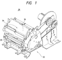
- Fig. 1 is a perspective view showing an external appearance of the printer of the first embodiment.
- the printer designated by reference numeral 30 is a printer of a type-ring select type, which is used for the electronic cash registers in a POS system.
- the printer 30 is composed of a printer body 32 and a paper supplying section disposed on the rear side of the printer body 32.
- An ink roll 35 is attached to and detached from the printer body 32.
- the printer body 32 includes a print head (not shown) having type rings for printing on a printing medium, a paper feeding mechanism (not shown) for feeding printing media, e.g., papers, to a printing position, and an automatic cutting device 34 for cutting a printed paper.
- a print head (not shown) having type rings for printing on a printing medium
- a paper feeding mechanism (not shown) for feeding printing media, e.g., papers, to a printing position
- an automatic cutting device 34 for cutting a printed paper.
- the cutting device 34 is located above the printer body 32 and has a construction as described hereunder.
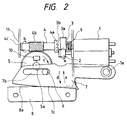
- the automatic cutting device 34 is schematically illustrated in Fig. 2.
- numeral 1 is a motor as a drive source; 2 is a motor gear as a spur gear; 3 is a transmission gear; 3a is a gear wheel; 3b is a first saw-tooth gear; 4 is a worm shaft; 4a is a second saw-tooth gear; 4b is a worm; 4c is a contact part; 5 is a helical gear; 5a is a cam part; 5b is a shaft; 6 is an blade drive pin; 7 is a movable blade; 7a is a shaft; 7b is an elongated hole; 7c is an edge; 8 is a stationary blade; 8a is an edge; 9 is a compression coiled spring; 10 is a detector; and 11 is a frame.
- the motor gear 2 is firmly attached to the motor shaft such that it is immovable in the rotation direction.
- the transmission gear 3, which is driven by the motor 1, includes the gear wheel 3a and the first saw-tooth gear 3b.
- the gear wheel 3a and the first saw-tooth gear 3b are molded into one piece construction.
- the thus constructed wheel and gear combination, or the transmission gear 3 is mounted while being movable in the center of rotation thereof.
- the gear wheel 3a is in mesh with the motor gear 2.
- the worm shaft 4 includes the second saw-tooth gear 4a and the worm 4b.
- the second saw-tooth gear 4a and the worm 4b are molded into one piece construction.
- the second saw-tooth gear 4a is in meshing engagement with the first saw-tooth gear 3b.
- the center of rotation of the worm shaft 4 is aligned with that of the transmission gear 3.
- One end (contact part 4c) of the worm shaft 4 is brought into contact with the frame 11, and held by the same.
- the helical gear 5 is rotatably supported by a shaft 5a and in meshing engagement with the worm 4b of the worm shaft 4.
- the blade drive pin 6 is fastened onto the helical gear 5, and slidably engages with the movable blade 7.
- the movable blade 7 may be turned about the shaft 7a, and has an elongated hole 7b and an edge 7c.
- the blade drive pin 6 is inserted into the elongated hole 7b of the movable blade 7.
- Fig. 3 is an explanatory diagram useful in explaining a relationship of forces in the automatic cutting device when the transmission gear 3 is coupled with the worm shaft 4.
- the number of revolutions of the motor is considerably reduced by the worm 4b.
- the blade drive pin 6 of the helical gear 5 turns which is inserted into the elongated hole 7b of the movable blade 7.
- the movable blade 7 is also turned about the shaft 7a in the direction of an arrow d by the turning blade drive pin 6, while at the same time the edge 7c of the movable blade 7 angularly slides on and along the edge 8a of the stationary blade 8.
- a printing paper (not shown) located between the movable blade 7 and the stationary blade 8 is cut.
- the printing paper is supplied from the paper supply mechanism (not shown), transported to a printing position, and subjected to printing, and thereafter cut.
- the helical gear 5 is further turned in the same direction.
- the movable blade 7 is turned in the direction of an arrow e .
- the turning helical gear 5 pushes the detector 10 with its cam part 5a. Then, the detector 10 produces a signal indicating that the movable blade 7 reaches its home position.
- the control unit (not shown) for controlling the driving and the turning direction of the motor 1 receives the signal from the detector 10, and stops the motor 1 and terminates the cutting operation of the automatic cutting device.
- a load F by the compression coiled spring 9 couples the first saw-tooth gear 3b of the transmission gear 3 with the second saw-tooth gear 4a of the worm shaft 4.
- the transmission gear 3 is turned in the direction h by the motor 1, and the worm shaft 4 is also turned since the surfaces of the gear teeth of the first saw-tooth gear 3b, which are sloped at a small angle, are brought into contact with the corresponding ones of the second saw-tooth gear 4a.
- the height of the sloped surfaces of the gear teeth of the transmission gear 3 is selected so that the transmission gear is movable horizontally.
- reaction force Fk F/tan( ⁇ + Atan ⁇ ) (Atan : arctangent)
- the spring load F and an angle ⁇ 1 of the steeply sloped surface of the gear teeth are selected so as to satisfy: Tm > T1 (Tm : starting torque Tm of the motor 1, T1 : frictional load torque).
- the gear tooth of each of the first and second saw-tooth gears 3b and 4a has two sloped surfaces; one is steep in slope (referred to as a steep slope) and the other is gentle (referred to as a gentle slope).
- the angles of the steep and gentle slopes are respectively denoted as ⁇ 1 and ⁇ ( ⁇ 1 > ⁇ ).
- the gentle slopes of the gear teeth of the first and second saw-tooth gears 3b and 4a are coupled with each other to thereby transmit the rotational torque of the motor 1 to the movable blade 7.
- the steep slopes of those gear teeth are coupled with each other and the motor 1 is reversed in turn.
- the worm shaft 4 is turned in the direction of an arrow f, and in turn the movable blade 7 (Fig. 2) returns to the home position.
- FIG. 4 Another automatic cutting device constructed according to the present invention will be described with reference to Fig. 4. As shown, when the transmission gear 3 and the worm shaft 4 are coupled with each other, the first and second saw-tooth gears 3b and 4a are loosely coupled in their rotational direction. The remaining structure of the Fig. 4 cutting device is substantially the same as of the Figs. 2 and 3 cutting device.
- the transmission gear 3 and the worm shaft 4 are coupled in the same manner as in the Figs. 2 and 3 cutting device.
- the movable blade 7 is locked and the motor 1 is reversely turned, the first saw-tooth gear 3d of the transmission gear 3 moves in the direction of an arrow j into meshing engagement with the second saw-tooth gear 4e of the worm shaft 4.
- the torque that must be produced by the motor may be reduced by a quantity corresponding to the inertia. This fact accrues to the reduction of the motor size and power consumed by the motor.
- a spring clutch is used in the power transmission mechanism of this third automatic cutting device, while the saw-tooth clutch gears are used in the above-mentioned two automatic cutting devices.
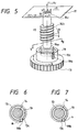
- FIG. 5 An external appearance of the third automatic cutting device is illustrated in perspective form in Fig. 5, and the cross sections each taken on line g - g in Fig. 5 are shown in Figs. 6 and 7.
- a twisted coiled spring 19 is wound around an arbor 14a of the worn shaft 14, as shown in Fig. 5.
- the inside diameter of the twisted coiled spring 19 is shorter than the diameter of the arbor 14a of the worm shaft 14.
- the interference of the coupling structure of the twisted coiled spring 19 and the arbor 14a, and the number of turns of the twisted coiled spring 19 define a transmission torque and a loosening torque in the clutch mechanism.
- a hook 19b is provided at one of the ends of the twisted coiled spring 19. It is inserted into a slit 13c of the transmission gear 13.
- the transmission gear 13 is rotated in the direction b by a motor gear, the twisted coiled spring 19 and the worm shaft 14 are also turned in the same direction.
- the movable blade is locked with something to interrupt to the turn of the blade, the worm shaft 14 is stopped in its rotation.
- the transmission gear 13 continues its rotation and transmits the rotational torque by the motor 1 to the subsequent stage in the power transmission mechanism.
- the slit 13c pushes the hook 19b of the twisted coiled spring 19 in the direction of an arrow m in Fig. 6.
- the twisted coiled spring 19 expands its inside diameter to be loosened.
- the twisted coiled spring 19 continues its turning while sliding on the peripheral outer surface of the arbor 14a of the worm shaft 14.
- the motor is reversely turned.
- the transmission gear 13 is turned in the direction c
- the slit 13c of the transmission gear 13 pushes the twisted coiled spring 19 in the direction of an arrow n .
- the twisted coiled spring 19 reduces its inside diameter to clamp the arbor 14a of the worm shaft 14; it turns the worm shaft 14 in the direction f ; and the movable blade returns to the home position with the aid of the helical gear being in mesh with the worm 14b.
- Electric power is supplied to a control system (not shown) contained in the printer, and to the motor 1 (step S1, Fig. 8).
- a timer starts time T (step S2).
- the system control contained checks if a state of the output signal of the detector 10 is an on or off (step S3) (the detector 10 is for detecting the home position of the movable blade 7). If the output signal is in an on state, the blade is at the home position. Therefore, the system control ceases the supply of electric power to the motor 1; it resets the timer; and it waits for an automatic cutting signal (step S4).
- control compares a time T count from the start of the power supplying to the motor with a time T0 (time of one cycle plus a margin time) (step S5). If T > T0, the automatic cutting device of the printer is abnormal, and therefore, control stops the supplying of electric power to the motor and displays an error message (step S6). If T ⁇ T0, control checks again a state of the output signal of the detector 10 and repeats this.
- control When in the step S5, control receives an automatic cutting signal, control supplies again electric power to the motor 1 (step S7), and counts time T of power supplying to the motor (step S8). Controls checks if a state of the output signal of the detector 10 is on or off (step S9). If it is on, the movable blade is at the home position. Therefore, control resets the timer and terminates the automatic cutting operation, and waits for the next incoming automatic cutting signal.
- control checks if T > T0 (step S10). If T ⁇ T0, control checks again a state of the output signal of the detector 10, and repeats this. If T > T0, there is a possibility that the movable blade 7 is locked with something obstructive. Then, control stops the power supplying to the motor, and resets the timer (step S12). In this way, a locking state of the movable blade 7 is detected.
- a control by the automatic cutting device 34 after the locking state of the movable blade is detected will be described with reference to Figs. 8 and 9.
- the motor 1 is rotated in the reverse direction after the supplying of electric power to the motor 1 is stopped (step S13). With the reverse turn, the transmission gear 3, worm shaft 4, and helical gear 5 in the power transmission mechanism are turned in the reverse direction, and the movable blade 7 is also turned in the same direction.
- Control commands the timer to count the time of the power supplying to the motor for the reverse turning (step S14), and checks a state of the output signal of the detector 10(step S15). If its state is on, the movable blade is at the home position, and therefore control stops the power supplying to the motor (step S16), and resets the timer.
- the movable blade 7 is a stand-by state.
- control checks again T and T0 (step S17). If T ⁇ T0, control returns to a routine to check a signal state of the output signal of the detector 10. If T > T0, something is wrong with the automatic cutting device of the printer. Then, control displays an error message (step S18).
- the automatic cutting device operates: After the error detection, control feeds electric power to the motor 1 to turn in the reverse direction; The movable blade 7 is turned in the direction opposite to the direction of the turning of the movable blade to cut the movable blade 7; and The movable blade 7 is returned to the home position.
- the automatic cutting device that thus functions has the following advantages. The work of removing the foreign material is easy. After the foreign matter is removed, the automatic cutting device can be restarted immediately, if required. This fact implies that provision of the device initializing time is not required, and hence that the cease time of the automatic cutting device is reduced.
- the power transmission mechanism may be located in the power transmission path ranging from the motor to the worm, while it is located between the transmission gear and the worm shaft in the above-mentioned embodiments.
- the worm is separated from the worm shaft of the transmission follower gear, while those are constructed in one-piece construction in the embodiments mentioned above.
- the worm is mounted on the worm shaft whose cross section is different from that of the worm in such a fashion that the worm is movable in the axial direction of the worm shaft, but is rotatable together with the worm shaft.
- the worm shaft may be movable, while the transmission gear as the transmission/drive gear is movable in the embodiments already stated.
- the present invention may be embodied as illustrated in Figs. 9 to 12 (fourth to sixth embodiments of the invention).
- a worm shaft 24, a transmission gear 24a, and a worm 24b are molded in one-piece construction.
- a helical gear 5 is in meshing engagement with the worm 24b of the worm shaft 24.
- the remaining construction of the automatic cutting device is substantially equal to the corresponding one of the Fig. 2 device.
- the worm shaft 24 is axially immovable in this state.
- the worm shaft 24 is turned by the motor 1 as in the case of Fig. 2.
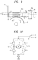
- a motor drive circuit also constructed according to the present invention is shown in Fig. 10.
- reference numeral 1 is a motor
- 12 is motor drive transistors 17
- 17 is a switch circuit, which is constructed by the utilization of transistors, for example.
- the switch circuit 17 selectively guides voltage E or E'' to the motor 1.
- Te is a motor torque when the voltage E is applied to the motor
- Te' is a motor torque when the voltage E' is applied to the motor.
- Numeral 18 is a resistor.
- an on signal is applied to the bases a and d of the transistors 12, and an off signal is applied to the bases b and c of the same. Current flows in the direction j.
- an on signal is applied to the bases c and b of the motor drive transistors 12, and an off signal is applied to the bases a and d of the transistors. Current flows in the direction i.
- reference numeral 15 is a current restricting circuit.
- the circuit restricts the value of the flowing current to below a predetermined value of current.
- Numeral 16 is a switch. In the forward turn of the motor, the transistors a and d of the motor drive transistors 12 are turned on and the transistors b and d are turned off. Current flows in the direction j. At this time, the switch 16 is turned off. Current flows into the motor, through the current restricting circuit 15. In the reverse turn, the transistors c and b of the motor drive transistors 12 are turned on and the transistors a and d are turned off. Current flows in the direction of an arrow i.
- the switch 16 is turned on. Current by-passes the current restricting circuit 15 and flows into the motor. The same voltage is used for both the forward and the reverse turns. In the forward turn, the current restricting circuit 15 acts and then Ts > Tc (Ts : torque for the reverse turn, Tc : torque for the forward turn)
- the DC motor which is used for the drive source in the above-mentioned embodiments, may be replaced with a stepping motor.
- the clutch as the transmission means and the motor control means may be combined within the scope of the invention.
- the locking function is enhanced in this case.
- the present invention is applied to the type-ring select type printer in the embodiments, it may be applied to any other suitable printer, for example, dot impact printer, thermal printer, ink jet printer or the like.
- the mechanism for turning back the movable blade within the stand-by position through the stand-by position and the cut position in turn by the forward rotation of the motor is not limited by the embodiment described above. Of course, it is applicable for employing a mechanism in such a manner that while rotating the motor in the forward direction, the movable blade moves from the stand-by position, and while the motor in the reverse direction, the movable blade moves from the cutting position to the stand-by position so that there is also enjoyed the effect and the advantage of the present invention.
- the clutch functions as a torque limiter. Therefore, if the blade locking occurs, the motor continues its rotation; the rotation inertia by the motor, for example, does not affect the frictional load; and the motor is not damaged.
- the construction of the present invention enables the worm to be turned by a torque greater than that transmitted if the motor is reversely turned; if the movable blade, for example, is abruptly stopped and a frictional load caused by the distortion energy is present, it can be returned to the original position highly probably since the reverse turn torque is large. Hence, when the motor is reversely turned, the worm wheel is reversely turned and the movable blade is returned to the home position.
Landscapes
- Engineering & Computer Science (AREA)
- Mechanical Engineering (AREA)
- Life Sciences & Earth Sciences (AREA)
- Forests & Forestry (AREA)
- General Engineering & Computer Science (AREA)
- Handling Of Sheets (AREA)
- Mechanical Operated Clutches (AREA)
Priority Applications (1)
| Application Number | Priority Date | Filing Date | Title |
|---|---|---|---|
| EP20040017350 EP1473167B1 (de) | 1997-04-09 | 1998-04-09 | Automatische Schneidvorrichtung, Verfahren zur Steuerung derselben und zugehöriges Druckgerät |
Applications Claiming Priority (3)
| Application Number | Priority Date | Filing Date | Title |
|---|---|---|---|
| JP9120397 | 1997-04-09 | ||
| JP91203/97 | 1997-04-09 | ||
| JP9120397 | 1997-04-09 |
Related Child Applications (1)
| Application Number | Title | Priority Date | Filing Date |
|---|---|---|---|
| EP20040017350 Division EP1473167B1 (de) | 1997-04-09 | 1998-04-09 | Automatische Schneidvorrichtung, Verfahren zur Steuerung derselben und zugehöriges Druckgerät |
Publications (3)
| Publication Number | Publication Date |
|---|---|
| EP0870621A2 true EP0870621A2 (de) | 1998-10-14 |
| EP0870621A3 EP0870621A3 (de) | 2000-02-02 |
| EP0870621B1 EP0870621B1 (de) | 2005-07-27 |
Family
ID=14019883
Family Applications (2)
| Application Number | Title | Priority Date | Filing Date |
|---|---|---|---|
| EP19980106572 Expired - Lifetime EP0870621B1 (de) | 1997-04-09 | 1998-04-09 | Automatische Schneidevorrichtung, Verfahren zur Steuerung derselben und zugehöriges Druckgerät |
| EP20040017350 Expired - Lifetime EP1473167B1 (de) | 1997-04-09 | 1998-04-09 | Automatische Schneidvorrichtung, Verfahren zur Steuerung derselben und zugehöriges Druckgerät |
Family Applications After (1)
| Application Number | Title | Priority Date | Filing Date |
|---|---|---|---|
| EP20040017350 Expired - Lifetime EP1473167B1 (de) | 1997-04-09 | 1998-04-09 | Automatische Schneidvorrichtung, Verfahren zur Steuerung derselben und zugehöriges Druckgerät |
Country Status (6)
| Country | Link |
|---|---|
| US (1) | US6164854A (de) |
| EP (2) | EP0870621B1 (de) |
| KR (1) | KR100429929B1 (de) |
| CN (1) | CN1123452C (de) |
| DE (2) | DE69830940T2 (de) |
| TW (1) | TW371640B (de) |
Cited By (5)
| Publication number | Priority date | Publication date | Assignee | Title |
|---|---|---|---|---|
| FR2889275A1 (fr) * | 2005-07-29 | 2007-02-02 | France Reducteurs Sas Soc Par | Dispositif de transmission entre un arbre primaire moteur et un arbre de sortie |
| FR3019242A1 (fr) * | 2014-03-28 | 2015-10-02 | Tordo Belgrano Sa | Systeme de renvoi d'angle a securite integree |
| WO2016199026A1 (en) * | 2015-06-10 | 2016-12-15 | Custom S.P.A. | Printing apparatus |
| CN106994840A (zh) * | 2017-04-13 | 2017-08-01 | 厦门汉印电子技术有限公司 | 一种带故障自动修复功能的打印机及其控制方法 |
| CN107323106A (zh) * | 2014-03-13 | 2017-11-07 | 富士通电子零件有限公司 | 切断装置、打印机装置及切断装置的控制方法 |
Families Citing this family (15)
| Publication number | Priority date | Publication date | Assignee | Title |
|---|---|---|---|---|
| JP2005003260A (ja) * | 2003-06-11 | 2005-01-06 | Hoshizaki Electric Co Ltd | オーガ式製氷機の保護装置 |
| DE102004006368A1 (de) * | 2004-02-09 | 2005-08-25 | Ludwig Ehrhardt Gmbh | Lineareinheit |
| US8016501B2 (en) * | 2004-09-30 | 2011-09-13 | Brother Kogyo Kabushiki Kaisha | Printer and printing method |
| JP4500746B2 (ja) * | 2005-08-29 | 2010-07-14 | 株式会社リコー | 穿孔処理装置、シート処理装置および画像形成装置 |
| JP4715457B2 (ja) | 2005-11-16 | 2011-07-06 | セイコーエプソン株式会社 | シート切断装置、およびこれを備えた印刷装置 |
| CN107128084B (zh) * | 2016-10-31 | 2023-02-28 | 深圳市鼎戟科技有限公司 | 一种用于打印机的刀片和刀片组合以及打印机 |
| WO2018188254A1 (zh) * | 2017-04-13 | 2018-10-18 | 厦门普瑞特科技有限公司 | 高效防卡死的动力装置及其带故障修复的打印机 |
| CN107097538B (zh) * | 2017-04-13 | 2023-01-31 | 厦门汉印电子技术有限公司 | 一种应用于打印机的高效防卡死的装置 |
| CN108245070A (zh) * | 2018-03-21 | 2018-07-06 | 北京智立行走科技有限公司 | 一种高稳定性自动剪切卫生纸的装置 |
| CN108943073A (zh) * | 2018-07-17 | 2018-12-07 | 李忠 | 一种新型的消防用旋转切割装置 |
| JP7091957B2 (ja) * | 2018-09-11 | 2022-06-28 | セイコーエプソン株式会社 | カッター装置およびこのカッター装置を備えたプリンター |
| JP7283114B2 (ja) * | 2019-02-21 | 2023-05-30 | セイコーエプソン株式会社 | カッター装置、および印刷装置 |
| CN110814435A (zh) * | 2019-11-28 | 2020-02-21 | 马鞍山楚锐科技信息咨询有限公司 | 薄板裁切装置 |
| JP2024020727A (ja) | 2022-08-02 | 2024-02-15 | セイコーエプソン株式会社 | 駆動機構、移動装置、及び、記録装置 |
| CN118848107A (zh) * | 2024-09-12 | 2024-10-29 | 杭州旺事来电动工具有限公司 | 一种自动化的锯片式加工设备 |
Family Cites Families (17)
| Publication number | Priority date | Publication date | Assignee | Title |
|---|---|---|---|---|
| US3675525A (en) * | 1970-08-21 | 1972-07-11 | William C Ellison | Machine for cutting rolls of sheet material |
| JPS5686081A (en) * | 1979-12-12 | 1981-07-13 | Mitsubishi Electric Corp | Driving circuit for dc motor |
| JPS5788884A (en) * | 1980-11-18 | 1982-06-02 | Mitsubishi Electric Corp | Regenerative energy absorbing circuit for motor |
| JPS58159695A (ja) * | 1982-03-17 | 1983-09-22 | Mitsubishi Electric Corp | 電動機制御装置 |
| US4735034A (en) * | 1986-01-09 | 1988-04-05 | Monarch Marking Systems, Inc. | Tag banding apparatus |
| US5123079A (en) * | 1986-03-10 | 1992-06-16 | Minolta Camera Kabushiki Kaisha | DC motor and controlling system therefor |
| JPH04164597A (ja) * | 1990-10-24 | 1992-06-10 | Canon Inc | 紙葉体切断装置 |
| JPH04366670A (ja) * | 1991-06-14 | 1992-12-18 | Matsushita Electric Ind Co Ltd | 用紙切断装置 |
| WO1993014937A1 (en) * | 1992-02-03 | 1993-08-05 | Curtis Manufacturing Company, Inc. | Paper burster and method |
| JPH0777711B2 (ja) * | 1992-05-29 | 1995-08-23 | スター精密株式会社 | オートカッター装置と機器 |
| JPH07121514B2 (ja) * | 1992-05-30 | 1995-12-25 | スター精密株式会社 | オートカッター装置 |
| JPH06210590A (ja) * | 1992-10-15 | 1994-08-02 | Murata Mach Ltd | ロール紙用切断装置 |
| JPH06155372A (ja) * | 1992-11-20 | 1994-06-03 | Hitachi Metals Ltd | シート材切断装置 |
| JPH07314386A (ja) * | 1994-05-30 | 1995-12-05 | Sanwa Shutter Corp | ロ−ル成形における走間剪断装置 |
| DE9416958U1 (de) * | 1994-10-21 | 1995-02-16 | Hengstler GmbH, 78554 Aldingen | Abschneidevorrichtung mit Motor |
| DE19502300A1 (de) * | 1995-01-26 | 1996-08-01 | Mohr Adolf Maschf | Vorrichtung zum Schneiden von blättrigem Gut |
| CN1093800C (zh) * | 1995-09-19 | 2002-11-06 | 精工爱普生株式会社 | 带有自动切纸器的打印装置 |
-
1998
- 1998-04-09 DE DE1998630940 patent/DE69830940T2/de not_active Expired - Lifetime
- 1998-04-09 CN CN98108781A patent/CN1123452C/zh not_active Expired - Fee Related
- 1998-04-09 DE DE1998635381 patent/DE69835381T2/de not_active Expired - Lifetime
- 1998-04-09 TW TW087105348A patent/TW371640B/zh not_active IP Right Cessation
- 1998-04-09 KR KR10-1998-0012506A patent/KR100429929B1/ko not_active Expired - Fee Related
- 1998-04-09 EP EP19980106572 patent/EP0870621B1/de not_active Expired - Lifetime
- 1998-04-09 EP EP20040017350 patent/EP1473167B1/de not_active Expired - Lifetime
- 1998-04-09 US US09/057,669 patent/US6164854A/en not_active Expired - Lifetime
Cited By (9)
| Publication number | Priority date | Publication date | Assignee | Title |
|---|---|---|---|---|
| FR2889275A1 (fr) * | 2005-07-29 | 2007-02-02 | France Reducteurs Sas Soc Par | Dispositif de transmission entre un arbre primaire moteur et un arbre de sortie |
| US7555968B2 (en) | 2005-07-29 | 2009-07-07 | France Reducteurs | Transmission device between a primary drive shaft and an output shaft and a vehicle equipped with such a device |
| CN107323106A (zh) * | 2014-03-13 | 2017-11-07 | 富士通电子零件有限公司 | 切断装置、打印机装置及切断装置的控制方法 |
| FR3019242A1 (fr) * | 2014-03-28 | 2015-10-02 | Tordo Belgrano Sa | Systeme de renvoi d'angle a securite integree |
| WO2016199026A1 (en) * | 2015-06-10 | 2016-12-15 | Custom S.P.A. | Printing apparatus |
| US20180134052A1 (en) * | 2015-06-10 | 2018-05-17 | Custom S.P.A. | Printing Apparatus |
| US10272702B2 (en) * | 2015-06-10 | 2019-04-30 | Custom S.P.A. | Printing apparatus |
| RU2721693C2 (ru) * | 2015-06-10 | 2020-05-21 | Кастом С.П.А. | Печатающее устройство |
| CN106994840A (zh) * | 2017-04-13 | 2017-08-01 | 厦门汉印电子技术有限公司 | 一种带故障自动修复功能的打印机及其控制方法 |
Also Published As
| Publication number | Publication date |
|---|---|
| CN1198987A (zh) | 1998-11-18 |
| TW371640B (en) | 1999-10-11 |
| EP1473167B1 (de) | 2006-07-26 |
| KR19980081209A (ko) | 1998-11-25 |
| DE69830940D1 (de) | 2005-09-01 |
| EP1473167A3 (de) | 2005-03-09 |
| DE69835381D1 (de) | 2006-09-07 |
| US6164854A (en) | 2000-12-26 |
| CN1123452C (zh) | 2003-10-08 |
| KR100429929B1 (ko) | 2004-07-27 |
| EP0870621B1 (de) | 2005-07-27 |
| DE69835381T2 (de) | 2007-09-27 |
| EP0870621A3 (de) | 2000-02-02 |
| EP1473167A2 (de) | 2004-11-03 |
| DE69830940T2 (de) | 2006-03-23 |
Similar Documents
| Publication | Publication Date | Title |
|---|---|---|
| EP0870621B1 (de) | Automatische Schneidevorrichtung, Verfahren zur Steuerung derselben und zugehöriges Druckgerät | |
| US6182550B1 (en) | Staggered gear for bi-directional operation | |
| US5222724A (en) | Paper feeder | |
| EP0718109B1 (de) | Papierabgabevorrichtung | |
| EP1609607B1 (de) | Bilderzeugungsvorrichtung | |
| US4609299A (en) | Printing apparatus | |
| US6684743B1 (en) | Staggered gear for bi-directional operation | |
| US5564842A (en) | Recording apparatus | |
| EP1020296B1 (de) | Leistungsübertragungsumschaltvorrichtung | |
| US5893670A (en) | Gear with teeth of decreasing height for a printer | |
| JP3617296B2 (ja) | オートカッタ装置及びこれを用いたプリンタ | |
| EP1186560B1 (de) | Schneidevorrichtung für Aufzeichnungspapier | |
| JP4285521B2 (ja) | 駆動伝達装置及び通信装置 | |
| US6334725B1 (en) | Drive transmitting apparatus and image forming apparatus | |
| US5823523A (en) | Auto sheet feeder for use in a printing apparatus | |
| JP2943276B2 (ja) | 給紙装置 | |
| US4971466A (en) | Printing apparatus having a rotatable member rotatable in incremental steps smaller than the pitch of a detent gear and including means for accurately retaining the rotatable member at a predetermined position when the detent mechanism is inoperable | |
| US6070706A (en) | Double acting roller/ball clutch gear | |
| JP3804724B2 (ja) | オートカッタ装置及びこれを用いたプリンタ | |
| JP2927618B2 (ja) | ギア機構 | |
| JPH10100499A (ja) | テープ巻取装置 | |
| JP2929551B2 (ja) | 回転刃駆動装置 | |
| JP3259747B2 (ja) | 給紙装置 | |
| JPH09286127A (ja) | サーマルプリンタ | |
| JPH06286278A (ja) | 過負荷に対する安全機能を備えた動力伝達機構及び該動力伝達機構を備えたプリンタ用リボン送り機構 |
Legal Events
| Date | Code | Title | Description |
|---|---|---|---|
| PUAI | Public reference made under article 153(3) epc to a published international application that has entered the european phase |
Free format text: ORIGINAL CODE: 0009012 |
|
| AK | Designated contracting states |
Kind code of ref document: A2 Designated state(s): DE FR GB IT |
|
| AX | Request for extension of the european patent |
Free format text: AL;LT;LV;MK;RO;SI |
|
| PUAL | Search report despatched |
Free format text: ORIGINAL CODE: 0009013 |
|
| AK | Designated contracting states |
Kind code of ref document: A3 Designated state(s): AT BE CH CY DE DK ES FI FR GB GR IE IT LI LU MC NL PT SE |
|
| AX | Request for extension of the european patent |
Free format text: AL;LT;LV;MK;RO;SI |
|
| RIC1 | Information provided on ipc code assigned before grant |
Free format text: 7B 41J 11/70 A, 7B 41J 11/66 B, 7B 26D 1/30 B, 7B 26D 5/08 B |
|
| 17P | Request for examination filed |
Effective date: 20000706 |
|
| AKX | Designation fees paid |
Free format text: DE FR GB IT |
|
| 17Q | First examination report despatched |
Effective date: 20031223 |
|
| GRAP | Despatch of communication of intention to grant a patent |
Free format text: ORIGINAL CODE: EPIDOSNIGR1 |
|
| GRAS | Grant fee paid |
Free format text: ORIGINAL CODE: EPIDOSNIGR3 |
|
| GRAA | (expected) grant |
Free format text: ORIGINAL CODE: 0009210 |
|
| AK | Designated contracting states |
Kind code of ref document: B1 Designated state(s): DE FR GB IT |
|
| REG | Reference to a national code |
Ref country code: GB Ref legal event code: FG4D |
|
| REF | Corresponds to: |
Ref document number: 69830940 Country of ref document: DE Date of ref document: 20050901 Kind code of ref document: P |
|
| ET | Fr: translation filed | ||
| PLBE | No opposition filed within time limit |
Free format text: ORIGINAL CODE: 0009261 |
|
| STAA | Information on the status of an ep patent application or granted ep patent |
Free format text: STATUS: NO OPPOSITION FILED WITHIN TIME LIMIT |
|
| 26N | No opposition filed |
Effective date: 20060428 |
|
| PGFP | Annual fee paid to national office [announced via postgrant information from national office to epo] |
Ref country code: GB Payment date: 20140409 Year of fee payment: 17 |
|
| PGFP | Annual fee paid to national office [announced via postgrant information from national office to epo] |
Ref country code: FR Payment date: 20140409 Year of fee payment: 17 Ref country code: IT Payment date: 20140415 Year of fee payment: 17 Ref country code: DE Payment date: 20140430 Year of fee payment: 17 |
|
| REG | Reference to a national code |
Ref country code: DE Ref legal event code: R119 Ref document number: 69830940 Country of ref document: DE |
|
| GBPC | Gb: european patent ceased through non-payment of renewal fee |
Effective date: 20150409 |
|
| PG25 | Lapsed in a contracting state [announced via postgrant information from national office to epo] |
Ref country code: GB Free format text: LAPSE BECAUSE OF NON-PAYMENT OF DUE FEES Effective date: 20150409 Ref country code: DE Free format text: LAPSE BECAUSE OF NON-PAYMENT OF DUE FEES Effective date: 20151103 Ref country code: IT Free format text: LAPSE BECAUSE OF NON-PAYMENT OF DUE FEES Effective date: 20150409 |
|
| REG | Reference to a national code |
Ref country code: FR Ref legal event code: ST Effective date: 20151231 |
|
| PG25 | Lapsed in a contracting state [announced via postgrant information from national office to epo] |
Ref country code: FR Free format text: LAPSE BECAUSE OF NON-PAYMENT OF DUE FEES Effective date: 20150430 |