EP0870641B1 - Messung der Leistungsanforderung zur Regelung eines elektrisch angetriebenen Golffahrzeugs - Google Patents
Messung der Leistungsanforderung zur Regelung eines elektrisch angetriebenen Golffahrzeugs Download PDFInfo
- Publication number
- EP0870641B1 EP0870641B1 EP98302817A EP98302817A EP0870641B1 EP 0870641 B1 EP0870641 B1 EP 0870641B1 EP 98302817 A EP98302817 A EP 98302817A EP 98302817 A EP98302817 A EP 98302817A EP 0870641 B1 EP0870641 B1 EP 0870641B1
- Authority
- EP
- European Patent Office
- Prior art keywords
- speed
- armature
- signal
- field current
- zero
- Prior art date
- Legal status (The legal status is an assumption and is not a legal conclusion. Google has not performed a legal analysis and makes no representation as to the accuracy of the status listed.)
- Expired - Lifetime
Links
- 230000033001 locomotion Effects 0.000 claims description 25
- 230000004044 response Effects 0.000 claims description 24
- 238000004804 winding Methods 0.000 claims description 17
- 230000001172 regenerating effect Effects 0.000 claims description 9
- 238000000034 method Methods 0.000 claims 7
- 230000000977 initiatory effect Effects 0.000 claims 3
- 238000010586 diagram Methods 0.000 description 6
- 230000007246 mechanism Effects 0.000 description 4
- 230000000994 depressogenic effect Effects 0.000 description 3
- 230000000694 effects Effects 0.000 description 3
- 230000009471 action Effects 0.000 description 2
- 230000008859 change Effects 0.000 description 2
- 230000007423 decrease Effects 0.000 description 2
- 230000010365 information processing Effects 0.000 description 2
- 241000273930 Brevoortia tyrannus Species 0.000 description 1
- 230000005355 Hall effect Effects 0.000 description 1
- 230000001133 acceleration Effects 0.000 description 1
- 230000003466 anti-cipated effect Effects 0.000 description 1
- 230000009118 appropriate response Effects 0.000 description 1
- 230000033228 biological regulation Effects 0.000 description 1
- 230000005540 biological transmission Effects 0.000 description 1
- 230000006835 compression Effects 0.000 description 1
- 238000007906 compression Methods 0.000 description 1
- 230000009849 deactivation Effects 0.000 description 1
- 230000003247 decreasing effect Effects 0.000 description 1
- 230000001419 dependent effect Effects 0.000 description 1
- 238000001514 detection method Methods 0.000 description 1
- 230000005284 excitation Effects 0.000 description 1
- 230000007274 generation of a signal involved in cell-cell signaling Effects 0.000 description 1
- 230000005484 gravity Effects 0.000 description 1
- 238000011835 investigation Methods 0.000 description 1
- 238000012986 modification Methods 0.000 description 1
- 230000004048 modification Effects 0.000 description 1
- 238000010248 power generation Methods 0.000 description 1
- 230000009467 reduction Effects 0.000 description 1
- 230000008929 regeneration Effects 0.000 description 1
- 238000011069 regeneration method Methods 0.000 description 1
- 230000000452 restraining effect Effects 0.000 description 1
- 230000001960 triggered effect Effects 0.000 description 1
Images


Classifications
-
- B—PERFORMING OPERATIONS; TRANSPORTING
- B60—VEHICLES IN GENERAL
- B60L—PROPULSION OF ELECTRICALLY-PROPELLED VEHICLES; SUPPLYING ELECTRIC POWER FOR AUXILIARY EQUIPMENT OF ELECTRICALLY-PROPELLED VEHICLES; ELECTRODYNAMIC BRAKE SYSTEMS FOR VEHICLES IN GENERAL; MAGNETIC SUSPENSION OR LEVITATION FOR VEHICLES; MONITORING OPERATING VARIABLES OF ELECTRICALLY-PROPELLED VEHICLES; ELECTRIC SAFETY DEVICES FOR ELECTRICALLY-PROPELLED VEHICLES
- B60L15/00—Methods, circuits, or devices for controlling the traction-motor speed of electrically-propelled vehicles
- B60L15/20—Methods, circuits, or devices for controlling the traction-motor speed of electrically-propelled vehicles for control of the vehicle or its driving motor to achieve a desired performance, e.g. speed, torque, programmed variation of speed
- B60L15/2009—Methods, circuits, or devices for controlling the traction-motor speed of electrically-propelled vehicles for control of the vehicle or its driving motor to achieve a desired performance, e.g. speed, torque, programmed variation of speed for braking
-
- B—PERFORMING OPERATIONS; TRANSPORTING
- B60—VEHICLES IN GENERAL
- B60L—PROPULSION OF ELECTRICALLY-PROPELLED VEHICLES; SUPPLYING ELECTRIC POWER FOR AUXILIARY EQUIPMENT OF ELECTRICALLY-PROPELLED VEHICLES; ELECTRODYNAMIC BRAKE SYSTEMS FOR VEHICLES IN GENERAL; MAGNETIC SUSPENSION OR LEVITATION FOR VEHICLES; MONITORING OPERATING VARIABLES OF ELECTRICALLY-PROPELLED VEHICLES; ELECTRIC SAFETY DEVICES FOR ELECTRICALLY-PROPELLED VEHICLES
- B60L50/00—Electric propulsion with power supplied within the vehicle
- B60L50/50—Electric propulsion with power supplied within the vehicle using propulsion power supplied by batteries or fuel cells
- B60L50/52—Electric propulsion with power supplied within the vehicle using propulsion power supplied by batteries or fuel cells characterised by DC-motors
-
- B—PERFORMING OPERATIONS; TRANSPORTING
- B60—VEHICLES IN GENERAL
- B60L—PROPULSION OF ELECTRICALLY-PROPELLED VEHICLES; SUPPLYING ELECTRIC POWER FOR AUXILIARY EQUIPMENT OF ELECTRICALLY-PROPELLED VEHICLES; ELECTRODYNAMIC BRAKE SYSTEMS FOR VEHICLES IN GENERAL; MAGNETIC SUSPENSION OR LEVITATION FOR VEHICLES; MONITORING OPERATING VARIABLES OF ELECTRICALLY-PROPELLED VEHICLES; ELECTRIC SAFETY DEVICES FOR ELECTRICALLY-PROPELLED VEHICLES
- B60L2200/00—Type of vehicles
- B60L2200/22—Microcars, e.g. golf cars
-
- Y—GENERAL TAGGING OF NEW TECHNOLOGICAL DEVELOPMENTS; GENERAL TAGGING OF CROSS-SECTIONAL TECHNOLOGIES SPANNING OVER SEVERAL SECTIONS OF THE IPC; TECHNICAL SUBJECTS COVERED BY FORMER USPC CROSS-REFERENCE ART COLLECTIONS [XRACs] AND DIGESTS
- Y02—TECHNOLOGIES OR APPLICATIONS FOR MITIGATION OR ADAPTATION AGAINST CLIMATE CHANGE
- Y02T—CLIMATE CHANGE MITIGATION TECHNOLOGIES RELATED TO TRANSPORTATION
- Y02T10/00—Road transport of goods or passengers
- Y02T10/60—Other road transportation technologies with climate change mitigation effect
- Y02T10/64—Electric machine technologies in electromobility
-
- Y—GENERAL TAGGING OF NEW TECHNOLOGICAL DEVELOPMENTS; GENERAL TAGGING OF CROSS-SECTIONAL TECHNOLOGIES SPANNING OVER SEVERAL SECTIONS OF THE IPC; TECHNICAL SUBJECTS COVERED BY FORMER USPC CROSS-REFERENCE ART COLLECTIONS [XRACs] AND DIGESTS
- Y02—TECHNOLOGIES OR APPLICATIONS FOR MITIGATION OR ADAPTATION AGAINST CLIMATE CHANGE
- Y02T—CLIMATE CHANGE MITIGATION TECHNOLOGIES RELATED TO TRANSPORTATION
- Y02T10/00—Road transport of goods or passengers
- Y02T10/60—Other road transportation technologies with climate change mitigation effect
- Y02T10/70—Energy storage systems for electromobility, e.g. batteries
-
- Y—GENERAL TAGGING OF NEW TECHNOLOGICAL DEVELOPMENTS; GENERAL TAGGING OF CROSS-SECTIONAL TECHNOLOGIES SPANNING OVER SEVERAL SECTIONS OF THE IPC; TECHNICAL SUBJECTS COVERED BY FORMER USPC CROSS-REFERENCE ART COLLECTIONS [XRACs] AND DIGESTS
- Y02—TECHNOLOGIES OR APPLICATIONS FOR MITIGATION OR ADAPTATION AGAINST CLIMATE CHANGE
- Y02T—CLIMATE CHANGE MITIGATION TECHNOLOGIES RELATED TO TRANSPORTATION
- Y02T10/00—Road transport of goods or passengers
- Y02T10/60—Other road transportation technologies with climate change mitigation effect
- Y02T10/72—Electric energy management in electromobility
Definitions
- Electric motor driven vehicles in particular golf cars, have many unique performance requirements that pose difficult obstacles to the design of control systems for direct current motors used as the primary means of propulsion.
- Shunt motors tend to have a characteristic response curve, namely a specific speed for a specific load. This is a result of a balancing of the input voltage and the back emf generated by the motion of the motor armature through the magnetic field established by the energized field coil. Speed and torque can be conveniently controlled by the adjustment of the voltage or current across or in either the armature or the field winding or both.
- motor control can be obtained through either the armature current or the field current, it is advantageous to rely on the variation of field current because of the lower current levels.
- the use of field current enables the use of low power, less expensive components that increase efficiency. It is the purpose of a preferred embodiment of this invention to provide a system of control which allows operation of the motor along its full range of response characteristics in accordance with a particular armature current to field current map.
- Basic speed control for such motors involves the use of a chopper circuit to supply pulses of voltage to the armature which are varied in duty cycle from 0 to 100% according to the desired speed in response to the manually operated throttle. Further refinement of the control is provided by an H bridge circuit operatively connected to vary the current in the field winding. These circuits are well known in the art.
- Regenerative braking involves the use of the back emf generated in the armature to retard rotation of the armature and therefore the speed of the golf car.
- Dynamic braking is accomplished by reversing the field current and dissipating the resultant energy generated as the armature rotation slows to a stop.
- a system is provided in one example for controlling a D-C motor which is constructed to propel a golf car.
- the motor is controlled to provide performance according to a predetermined field current map which calls for a particular performance response to specified performance events.
- the performance events are detected by sensing actual speed and armature current and the performance response is triggered by adjustment of the field current or other appropriate parameters.
- a performance map correlating actual speed to various events and specifying the field current response is designed for the motor used.
- an armature current performance map is similarly constructed correlating armature current to particular performance events.
- a selection of performance maps are provided which are designed for specific types of terrain, for example, level ground, all-terrain, small to medium grades, and steep grades.
- the motor is a shunt wound motor having independently excited armature and field windings.
- the basic input to the armature of the motor is supplied through a pulse width modulated chopper circuit which varies the width of its output voltage pulse (duty cycle) in response to the throttle of the golf car.
- Full control of the input to the field winding is gained by the supply of power to an H bridge circuit.
- Armature current is continuously sensed to provide an indication of the status and performance of the car during operation. In addition actual speed of the golf car is sensed. At a predetermined level of armature current indicative of going up a hill, the field current is adjusted to provide a higher torque at a specific speed.
- sensed speed indicates a predetermined over speed condition, as for example when the vehicle coasts, field current is increased to enhance regeneration and the resultant braking.
- a predetermined delay is initiated and if the speed sensor indicates thereafter, that the vehicle has begun to roll, an appropriate field current can be applied to limit the speed of the car.
- the at rest condition is continuously monitored by the speed sensor, if movement of the car begins, the direction can be established and the circuitry will apply a current to the field winding to initiate dynamic braking.
- This invention is described in relation to a golf car but is applicable to any vehicle which utilizes a direct current electric motor to drive its wheels.
- the motor which is used consists of a shunt type with independently excited armature and field windings such as an Advanced D.C. Motors model no. AY6-4002.
- a typical control circuit is shown and described in U.S. Patent No. 5,264,763 which is incorporated herein by reference.
- the control system of this invention is shown in Figure 2 and consists of motor armature 1 together with its associated chopper control circuit 3 and field coil 2 together with its associated H-bridge control circuit 4.
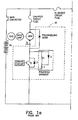
- armature 1 and field coil 2 armature 1, with its control 3 and field coil 2, with its control 4 are each connected directly to DC supply 8 in a parallel relation as shown in Figures 1a and 1b as well as Figure 2 .
- the armature 1 is independently excited by a chopper circuit 3 which provides a pulsed voltage to armature 1.
- the current through the armature is varied by modulating the pulse width of the chopper output.
- a typical circuit for the chopper 3 is shown at 18 of Figure 1a .
- a mechanical throttle such as a foot pedal 9, shown in Figure 2 , may be employed to provide a signal to vary the chopper output.
- the current through the field coil 2 is supplied through H bridge circuit 4.
- a typical H bridge circuit is shown at 16 of Figure 1b .
- the field current is used as the main variable in the control circuit of this invention and is monitored by a current sensor 7.
- An armature current monitor 6 is connected in the armature circuit to sense the current flowing in the armature and generate a signal which is used as an indicator of the performance needs of the motor in the operation of the golf car.
- a voltage sensor 10 is provided to sense the armature voltage.
- a controller 5 is used to adjust the field current in response to performance conditions indicated by the armature current monitor signal.
- a speed sensor 11 is used to obtain signals indicative of the actual speed of the vehicle.
- This sensor 11 may be a simple Hall Effect device operatively associated with the armature shaft of the motor. Since this is the shaft which drives the wheels of the golf car, the speed sensor 11 will accurately reflect the actual speed of the car.
- the addition of the speed sensor 11 will simplify the detection of certain events, for example the starting or stopping of the car, overspeed, unintended movement, and stalling. With the speed sensor 11, armature current need not be monitored while the vehicle is stopped nor is a residual field necessary as in the prior system. The speed sensor 11 will provide a more precise regulation of vehicle top speed.
- the controller 5 is a microprocessor which is constructed to provide the well known and typical functions of receiving data, storing data, comparing data, and signal generation. Controller 5 compares the actual armature current and speed to predetermined data and generates a signal to adjust the field current according to the performance requirements of the golf car. The actual field current is monitored by field current monitor 7 which generates a signal to allow the controller 5 to determine when the current in field coil 2 is at the desired level. Controller 5 continuously compares the actual field current to the desired field current level generated at specific values of armature current.
- the typical motor used to propel a vehicle such as a golf car has an armature 1 which is mounted for rotation through a magnetic field set up by a field coil 2.
- the armature 1 and field coil 2, with their associated control circuits 3 and 4 respectively, are connected in parallel to a common DC voltage source such as a battery 8.
- a solenoid 13 controls the current to the armature control circuit 3 and can be actuated by the controller 5 when keyed switch 15 indicates the need to turn on the motor.
- the armature 1 and field coil 2 are independently excited.
- the motor is controlled through adjustment of the output of chopper circuit 3 by a throttle 9, such as a foot pedal.
- a sensor is provided on the foot pedal which generates a signal, the amplitude of which is proportional to the distance the pedal is depressed.
- a separate micro switch indicates when the throttle is engaged or released. Forward or Reverse modes of operation may be selected by a direction lever 12, the position of which is indicated by micro switches operatively associated with the lever 12. These indications are fed to the controller 5 to provide data relating to the sensed positions of the throttle 9 and lever 12.
- H bridge circuit 4 is particularly well adapted to enhance the effects of braking through adjustment of the field in the proper direction to increase the back emf.
- Circuit 4 can also accomplish field current reversal in opposition to armature rotation to provide dynamic braking. In the instance of regenerative braking, a current may be generated which is fed back to the battery through path 14. During dynamic braking, a majority of the current generated is dissipated in the armature.
- armature current is directly effected by the generation of the back emf, armature current provides a convenient indicator of some particular conditions which, without control adjustment, could result in undesirable performance.
- a performance map can be developed which relates particular performance events to appropriate responses.
- a performance map is extrapolated which relates actual data to desired performance and needed adjustment.
- two basic maps are provided, a map relating to stopping and starting, and a map relating to movement of the vehicle on grades.
- Each map consists of individual performance events or conditions, the actual parameter value or values that indicate the occurrence of an event or the presence of a condition, and a desired field current or in some instances armature voltage which enhances performance of the event. These maps are stored in controller 5 for reference when the sensors indicate the presence of a predetermined condition. Controller 5 can then compare actual field current to the desired field current from the map and adjust the field current accordingly.
- the controller 5 is supplied with data relative to a condition of speed decay caused by the golf car proceeding up a hill or other inclined surface. At this time more torque is needed and the speed tends to decline.
- the normal operating range of armature current used in a golf car type vehicle is approximately 0 to 300 amperes depending on a wide variety of factors. On level ground it is anticipated that the motor used in this particular application will draw approximately 35 amps while proceeding at a reasonable speed. As the golf car begins to climb a hill, the armature current may jump to 150 amps or more depending on the grade.
- an adjustment signal is generated to cause a change in the field current which will increase the torque available.
- armature current levels may be designed into the controller 5 which correspond to the armature current expected at a specific grade.
- a signal is generated proportional to the desired field current.
- the field current is then adjusted to provide increasing torque at a consistent speed. In this manner the uphill performance of the golf car is greatly improved.
- a performance curve P is illustrated in Figure 4 . These data will vary according to the characteristic curves T of the electric motor used. As shown in curve P of Figure 4 , the field current can be varied between approximately 0 to 20 amps. As shown, under normal conditions, the field current is held at approximately 4 amps and then increased or decreased, as required, when a predetermined current level is reached.
- the speed sensor signal is used and compared to a specific speed limit for the application.
- a speed of between 13 or 14 miles per hour is a reasonable limit and this can be set in a performance map for reference by the controller 5.
- Controller 5 will generate a responsive change in field current, if overspeed occurs.
- the field current adjustment in response to overspeed will be to enhance the effect of regenerative braking, namely by increasing the field current.
- a zero speed signal indicates a stopped condition.
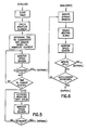
- the controller 5 upon the receipt of a zero speed signal, the controller 5 initiates a timed interval of about 2 seconds. If, after the interval has expired, the throttle is not depressed, a stopped condition is indicated. The controller 5 is provided with such data and responds by deactivating the motor. Deactivation is accomplished by reducing the duty cycle of control circuits 3 and 4 to zero and opening solenoid 13. Thereafter the controller 5 continues to monitor signals from the speed sensor to insure movement does not occur. In the event that movement begins, as indicated by the speed sensor, dynamic braking is applied. This event is referred to as walkaway in figure 6 .
- the speed sensor generates a signal proportional to the actual speed of the golf car while the field current monitor will generate a signal relative to the direction of movement.
- These speed signals are received by the controller 5, as shown in figure 2 , and provide a basic indication of whether the vehicle is moving and in which direction, forward or reverse.
- the speed signals allow the controller 5 to determine if the vehicle is moving opposite to the direction indicated by the position of the transmission lever 12. This indication will match a roll back condition on a hill identified in the performance map which is supplied to the controller 5. In this case a field current would be generated to oppose the movement and employ dynamic braking. If the speed signal is consistent with the movement desired by the user, the performance map will be searched for speed limit data to determine if an over speed condition is present. When over speed is indicated, regenerative braking will be initiated.
- an indicator of speed also provides critical data during a stalled condition.
- a zero speed signal in association with a depressed throttle will indicate a condition which may generate excessive armature current through a single point on the commutator. Such a situation could result while using the motor to hold position on a hill or while the car is impeded by an obstacle. If the condition is allowed to continue for an extended period, damage to the motor commutator could result.
- a time limit is provided, after which the armature control circuit duty cycle will be reduced as needed to avoid damage. This may be accomplished in steps with a reduction in armature duty cycle occurring at an interim points.
- the flow diagram of figure 5 illustrates the information processing of the performance map of the stalled condition.
- the time limit is contained in a look-up table stored in controller 5 which relates time, armature current and current limits.
- Dynamic braking involves the reversal of the field current to oppose the movement of the vehicle.
- the energy generated in dynamic braking is generally dissipated as heat in a resistive load.
- dynamic braking is used and dissipated through the armature as the load. This type of braking is called "plug" braking.
- plug braking
- This option is made available when the throttle pedal 9 is released indicating a desire to stop, thereby creating another event and response for the performance map referred to as a walkaway. The information processing of this condition is shown in figure 3 .
- Dynamic braking is also the response to a rollback event.
- the performance map of a preferred embodiment of this invention is comprised of several basic speed indications, events and responses as described above. These may be selectively grouped for selection where the terrain has consistent characteristics for example flat ground, hills, severe grades or all terrain. Through the use of appropriate means, for example, switches or plug in data cards, the controller 5 is instructed to use the map which accommodates the particular terrain. For example, a flat ground map may be designed with a higher speed for the overspeed condition or dynamic braking may be limited.
Landscapes
- Engineering & Computer Science (AREA)
- Power Engineering (AREA)
- Transportation (AREA)
- Mechanical Engineering (AREA)
- Life Sciences & Earth Sciences (AREA)
- Sustainable Development (AREA)
- Sustainable Energy (AREA)
- Control Of Direct Current Motors (AREA)
- Electric Propulsion And Braking For Vehicles (AREA)
Claims (13)
- Verfahren zum Steuern eines elektrischen Gleichstrommotors, um ein gewünschtes Leistungsprofil zu erhalten, wobei der Gleichstrommotor unter der Kontrolle eines Benutzers für den Antrieb eines Golfwagens verwendet wird, wobei der Motor Anker- (1) und Feldspulen (2) hat, die durch eine Spannungsquelle unabhängig voneinander angesteuert werden, um Anker- und Feldströme zu erzeugen, wobei der Motor ein charakteristisches Leistungsprofil zeigt, welches vorbestimmte Ankerstromniveaus, welche einen speziellen Betriebsvorgang anzeigen, vorbestimmte Geschwindigkeitswerte, welche einen speziellen Betriebsvorgang anzeigen und vorbestimmte Feldstromniveaus hat, welche in Reaktion auf einen speziellen Betriebsvorgang die Leistungsfähigkeit des Motors verbessern, um das gewünschte Leistungsprofil zu erhalten, wobei der spezielle Betriebsvorgang ausgewählt wird aus der Gruppe, welche aufweist:Stoppen und Starten des Golfwagens, und Bewegen des Golfwagens auf Steigungen, wobei das Verfahren die Schritte aufweist:(i) Erfassen des Ankerstroms des Motors und Erzeugen eines diesbezüglichen Signals,(ii) Erfassen des Feldstromes des Motors und Erzeugen eines diesbezüglichen Signales,(iii) Erfassen der Geschwindigkeit des Golfwagens und Erzeugen eines diesbezüglichen Signals unter Verwendung einer Geschwindigkeitsüberwachungseinrichtung, die so angeschlossen ist, dass sie die Bewegung des Goffwagens erfasst,(iv) Vergleichen des Ankerstromsignals mit dem vorbestimmten Ankerstromniveau, um das Auftreten des Betriebsvorganges zu identifizieren,(v) Vergleichen des Geschwindigkeitssignals mit dem vorbestimmten Geschwindigkeitswert, um das Auftreten des Betriebsvorganges zu identifizieren,(vi) Erzeugen eines Foldstromeinstellungssignals für den speziellen Betriebsvorgang gemäß den vorbestimmten Feldstromniveaus, wenn das Signal des Ankerstroms anzeigt, dass ein Betriebsvorgang aufgetreten ist, und(vii) Vergleichen des Feldstromsignals mit dem Feldstromeinstellungssignal und Einstellen des Feldstromes, um den vorbestimmen Feldstrom zu erhalten.
- Verfahren nach Anspruch 1, welches weiterhin die Schritte aufweist:Einstellen eines vorbestimmten Geschwindigkeitswertes auf null,Erfassen eines Zustandes, wenn ein Benutzer eine Eingabe bereitstellt, die Geschwindigkeit des Golfwagens auf null zu reduzieren,Auslösen eines Zeitintervalls wenn die erfasste Geschwindigkeit null ist,Erzeugen eines Feldstromeinstellungssignals nach Verlöschen des Zeitintervalls, wenn die erfasste Geschwindigkeit eine andere als null ist, wobei das Einstellsignal bewirkt, dass der aufzubringende Feldstrom ein dynamisches Bremsen auslöst.
- Verfahren nach Anspruch 1, welches die weiteren Schritte aufweist:Einstellen eines vorbestimmten Geschwindigkeitswertes auf null,Erfassen eines Zustandes, in welchem ein Benutzer eine Eingabe vornimmt, um die Geschwindigkeit des Golfwagens auf null zu reduzieren,Auslösen eines Zeitintervalls, wenn die erfasste Geschwindigkeit null ist, undErzeugen eines Einstellsignals nach dem Ablauf des Zeitintervalls, wenn die erfasste Geschwindigkeit null ist, wobei das Einstellungssignal bewirkt, dass die Spannungsquelle für den Anker auf null reduziert wird.
- Verfahren nach Anspruch 1, weiches die weiteren Schritte aufweistEinstellen eines vorbestimmten Geschwindigkeitswertes im Wesentlichen auf null,Erfassen eines Zustandes, in welchem ein Benutzer eine Eingabe bereitstellt, um zu bewirken, dass der Motor den Golfwagen in Bewegung setzt,Auslösen eines Zeitintervalls, wenn die erfasste Geschwindigkeit null ist, und Erzeugen eines Einstellsignals nach Ablauf des Zeitintervalls, wenn die erfasste Geschwindigkeit noch immer null ist, wobei das Einstellsignal die Spannungsversorgung für den Anker reduziert, um dadurch eine Beschädigung des Motors zu verhindern.
- Verfahren nach Anspruch 1, welches die Schritte aufweist:Erfassen eines Zustands, in welchem der Motor den Golfwagen antreibt,Setzen einer vorbestimmten Geschwindigkeit des Golfwagens auf eine spezifische maximale Geschwindigkeit, undErzeugen eines Feldstromeinstellungssignals, wenn die erfasste Geschwindigkeit den vorbestimmten Maximalwert übersteigt, wobei das Einstellungssignal eine Zunahme des Feldstromes bewirkt, um ein regeneratives Bremsen zu verstärken.
- Verfahren nach Anspruch 1, welches weiterhin die Schritte aufweist:Auswählen einer Mehrzahl vorbestimmter Ankerstromniveaus, Geschwindigkeitswerte und Feldstromniveaus zu vorbestimmten Gruppen gemäß einem gewünschten Leistungsfählgkeitsprofil für ein charakteristisches Gelände, undAuswählen einer Klasse gemäß dem aktuellen Gelände.
- Verfahren zum Steuern der Leistungsfähigkeit eines Gleichstrommotors, welcher verwendet wird für einen Golfwagen und welcher aufweist:Eine Spannungsquelle (8),Einen Motoranker (1), der über einen Ankersteuerungsschaltkreis mit der Spannungsquelle verbunden ist, um eine unabhängige Steuerung des Ankers bereitzustellen,Eine Motorfeldwicklung (2), die mit dem Motoranker für den Betrieb magnetisch gekoppelt und über einen Feldwicklungssteuerschaltkreis direkt mit der Spannungsquelle verbunden ist, um eine Steuerung der Feldwicklung unabhängig von dem Anker bereitzustellen,Eine Ankerstromüberwachungseinrichtung (3), die so angeschlossen ist, dass sie den Strom in dem Anker erfasst und ein diesbezügliches Signal erzeugt,Eine Feldstromüberwachungseinrichtung (4), die so angeschlossen ist, dass sie den Strom in der Feldwicklung erfasst und ein diesbezügliches Signal erzeugt,Eine Geschwindigkeitsüberwachungseinrichtung (11), die so angeschlossen ist, dass sie die Bewegung des Golfwagens erfasst und ein diesbezügliches Signal erzeugt,Eine Steuerung (5), die so angeschlossen ist, dass sie Signale von den Überwachungseinrichtungen für den Ankerstrom, den Feldstrom und die Geschwindigkeit empfängt und welche weiter aufweist:Einrichtungen, die so ausgelegt sind, dass sie vorbestimmte Ankerstromwerte empfangen, die eine Anzeige für einen speziellen Leistungsfähigkeitszustand darstellen, ausgewählt aus der Gruppe, welche aufweist:Stoppen und Starten des Golfwagen sowie Bewegung des Golfwagens auf Steigungen,Einrichtungen, die dafür ausgelegt sind, die vorbestimmten Geschwindigkeitswerte aufzunehmen, welche einen spezifischen Leistungsfähigkeitszustand anzeigen, ausgewählt aus der Gruppe, welche aufweist:Stoppen und Starten des Golfwagens und Bewegung des Golfwagens auf Steigungen,Einrichtungen, die dafür ausgelegt sind, vorbestimmte Feldstromwerte aufzunehmen, die eine Anzeige für die gewünschte Leistungsfähigkeitsreaktion auf den Leistungsfähigkeitszustand darstellen,Einrichtungen, die dafür ausgelegt sind, die Ankerstromsignale mit dem vorbestimmten Ankerstromwert zu vergleichen, um das Auftreten des Leistungsfähigkeitszustandes zu erkennen,Einrichtungen, die dafür ausgelegt sind, das Geschwindigkeitssignal mit dem vorbestimmten Geschwindigkeitswert zu vergleichen, um das Auftreten des Leistungsfähigkeitszustandes zu erkennen,Einrichtungen, die dafür ausgelegt sind, das Signal der Feldstromüberwachungseinrichtung mit dem vorbestimmten Feldstromwert zu vergleichen für die gewünschte Reaktion auf den erkannten Leistungszustand und um ein Feldstromeinstellungssignal zu erzeugen, undwobei der Feldwicklungssteuerschaltkreis so ausgestaltet ist, dass er den Feldstrom in Reaktion auf das Feldstromeinstellungssignal einstellt.
- Vorrichtung nach Anspruch 7, welche weiterhin Einrichtungen aufweist, die in der Weise betreibbar sind, dass sie erfassen, wenn der Motor nicht erregt bzw. angesteuert wird, und wobei
Ein vorbestimmter Geschwindigkeitswert auf null gesetzt wird, und
Die Steuerung (5) so ausgestaltet ist, dass sie in Reaktion darauf, dass das Signal der Geschwindigkeitsüberwachungseinrichtung eine Geschwindigkeit von null anzeigt, ein Zeitintervall auslöst und ein Signal erzeugt, um zu bewirken, dass der Steuerschaltkreis für die Feidstromwicklung die Richtung des Feldstromes umkehrt und ein dynamisches Bremsen bei Ablauf des Intervalls zu bewirken, wenn das Signal der Geschwindigkeitsüberwachungseinrichtung eine Geschwindigkeit anzeigt, die nicht null ist. - Vorrichtung nach Anspruch 7, wobei:Ein vorbestimmter Geschwindigkeitswert auf null gesetzt wird, undDie Steuerung (5) so ausgestaltet ist, dass sie in Reaktion darauf, dass das Signal der Geschwindigkeitsüberwachungseinrichtung eine Geschwindigkeit von null anzeigt, ein Zeitintervall auslöst und ein Signal erzeugt, um zu bewirken, dass der Ankersteuerschaltkreis die Spannung für den Anker auf null reduziert, wenn das Intervall abgelaufen ist, wenn das Geschwindigkeitswertsignal der Geschwindigkeitsüberwachungseinrichtung noch immer eine Geschwindigkeit von null anzeigt.
- Vorrichtung nach Anspruch 7, welche weiterhin eine Einrichtung aufweist, die so betreibbar ist, dass sie einen Zustand erfasst, wenn der Motor erregt ist bzw. unter Strom steht, um eine Bewegung des Golfwagens zu bewirken, und wobei weiterhin:Ein vorbestimmter Geschwindigkeitswert auf null gesetzt wird, undDie Steuerung (5) so ausgestaltet ist, dass sie in Reaktion darauf, dass das Signal der Geschwindigkeitsüberwachungseinrichtung eine Geschwindigkeit von null anzeigt, ein Zeitintervall auslöst, und bei Ablauf des Zeitintervalls ein Signal erzeugt, um zu bewirken, dass der Ankersteuerschaltkreis die Spannung für den Anker reduziert und dadurch eine Beschädigung des Motors verhindert, wenn das Signal der Geschwindigkeitsüberwachungseinrichtung immer noch eine Geschwindigkeit von null anzeigt.
- Vorrichtung nach Anspruch 7, welche weiterhin Einrichtungen aufweist, die in der Weise betreibbar sind, dass sie einen Zustand erfassen, in welchem der Golfwagen sich bewegt und wobei weiterhin:Ein vorbestimmter Geschwindigkeitswert auf einen vorbestimmten Maximalwert gesetzt wird, undDie Steuerung (5) so ausgestaltet ist, dass sie ein Feldstromeinstellungssignal erzeugt, um einen Anstieg in dem Feldstrom zu bewirken, um ein regeneratives Bremsen in Reaktion darauf zu verstärken, dass das Signal der Geschwindigkeitsüberwachungseinrichtung eine Geschwindigkeit anzeigt, die den vorbestimmten Maximalwert übersteigt.
- Vorrichtung nach Anspruch 7, welche weiterhin aufweist:Einrichtungen, die dafür ausgelegt sind, einen Zustand zu erfassen, wann der Motor unter Strom steht, um eine Bewegung des Golfwagens in einer bestimmten Richtung zu bewirken, undEinrichtungen, die dafür ausgelegt sind, die aktuelle Bewegungsrichtung des Golfwagens zu erfassen, undWobei weiterhin die Steuerung (5) so ausgelegt ist, dass sie ein Signal erzeugt, um zu bewirken, dass der Feldwicklungssteuerschaltkreis die Richtung des Feldstromes umkehrt, um ein dynamisches Bremsen entgegen der aktuellen Bewegung in Reaktion darauf zu bewirken, dass die aktuelle Bewegungsrichtung der Erregungsrichtung entgegengesetzt ist.
- Vorrichtung nach Anspruch 7, wobei die Steuerung weiterhin aufweist:Einrichtungen, die so ausgelegt sind, dass sie eine Mehrzahl der vorbestimmten Werte des Ankerstroms, der Geschwindigkeit und des Feldstromes empfängt, die entsprechend dem gewünschten Leistungsprofil für ein charakteristisches Gelände (Terrain) gruppiert sind, undEinrichtungen die dafür ausgelegt sind, eine Gruppe entsprechend dem aktuellen Gelände auszuwählen.
Applications Claiming Priority (2)
| Application Number | Priority Date | Filing Date | Title |
|---|---|---|---|
| US08/843,010 US5793175A (en) | 1995-01-19 | 1997-04-11 | Performance event sensing for control of electric motor driven golf car |
| US843010 | 1997-04-11 |
Publications (3)
| Publication Number | Publication Date |
|---|---|
| EP0870641A2 EP0870641A2 (de) | 1998-10-14 |
| EP0870641A3 EP0870641A3 (de) | 1999-03-17 |
| EP0870641B1 true EP0870641B1 (de) | 2010-08-11 |
Family
ID=25288823
Family Applications (1)
| Application Number | Title | Priority Date | Filing Date |
|---|---|---|---|
| EP98302817A Expired - Lifetime EP0870641B1 (de) | 1997-04-11 | 1998-04-09 | Messung der Leistungsanforderung zur Regelung eines elektrisch angetriebenen Golffahrzeugs |
Country Status (5)
| Country | Link |
|---|---|
| US (1) | US5793175A (de) |
| EP (1) | EP0870641B1 (de) |
| JP (1) | JPH10309005A (de) |
| CA (1) | CA2233866C (de) |
| DE (1) | DE69841817D1 (de) |
Families Citing this family (23)
| Publication number | Priority date | Publication date | Assignee | Title |
|---|---|---|---|---|
| US6021251A (en) * | 1997-07-08 | 2000-02-01 | Crown Equipment Corporation | Compensated field current control for a separately excited DC motor |
| US6031965A (en) * | 1997-07-08 | 2000-02-29 | Solaria Research Enterprise, Ltd. | Separately excited DC motor with boost and de-boost control |
| US6288508B1 (en) * | 1997-11-05 | 2001-09-11 | Yamaha Hatsudoki Kabushiki Kaisha | Electric motor for a vehicle having regenerative braking and reverse excitation braking |
| JP4093515B2 (ja) * | 1999-05-12 | 2008-06-04 | 本田技研工業株式会社 | 前後輪駆動車両 |
| US6462506B2 (en) | 1999-12-30 | 2002-10-08 | Textron Inc. | Electric golf car with low-speed regenerative braking |
| US6293077B1 (en) | 2000-05-02 | 2001-09-25 | Mtd Products Inc | Deck attachment and lift system |
| US6373207B1 (en) | 2000-07-11 | 2002-04-16 | Kalish Inc. | Braking system for a DC motor |
| US6943510B2 (en) | 2001-08-06 | 2005-09-13 | Black & Decker Inc. | Excitation circuit and control method for flux switching motor |
| JP4217615B2 (ja) * | 2001-08-06 | 2009-02-04 | ブラック アンド デッカー インコーポレイテッド | 励弧回路および、フラックス切替モーターの励起方法 |
| JP2005312109A (ja) * | 2004-04-19 | 2005-11-04 | Moric Co Ltd | 電動車両の回生制動システム |
| JP2005333729A (ja) * | 2004-05-20 | 2005-12-02 | Moric Co Ltd | 電動車両の駆動制御装置 |
| JP2006025470A (ja) | 2004-07-06 | 2006-01-26 | Moric Co Ltd | 電動車両の駆動制御装置 |
| CN101209681B (zh) * | 2006-12-26 | 2010-09-29 | 比亚迪股份有限公司 | 电动汽车下坡状态下电机输出转矩控制系统及控制方法 |
| CN101209682B (zh) * | 2006-12-26 | 2010-09-29 | 比亚迪股份有限公司 | 电动汽车爬坡状态下电机输出转矩控制系统及控制方法 |
| US7926889B2 (en) * | 2007-10-29 | 2011-04-19 | Textron Innovations Inc. | Hill hold for an electric vehicle |
| EP2269177A4 (de) | 2008-03-24 | 2014-01-22 | Strata Proximity Systems Llc | Einstellung eines elektromagnetischen felds zur proximitätsdetektion |
| JP5067326B2 (ja) * | 2008-09-16 | 2012-11-07 | 新神戸電機株式会社 | 電磁誘導式ゴルフカートの走行制御方式 |
| NZ588233A (en) | 2010-09-28 | 2011-06-30 | Dynamic Controls | Dynamically adjusting a compensation term based on a stored profile for a motor |
| DE102011118488A1 (de) * | 2011-11-11 | 2013-05-16 | Maschinenfabrik Reinhausen Gmbh | Motorantrieb für Stufenschalter |
| WO2014152951A1 (en) | 2013-03-14 | 2014-09-25 | Boosted, Inc. | Dynamic control for light electric vehicles |
| US10486051B2 (en) | 2017-09-26 | 2019-11-26 | Boosted, Inc. | Backpack for a personal transport vehicle |
| US20200384976A1 (en) * | 2019-06-05 | 2020-12-10 | Avx Electronics Technology Limited | System for Sensing a Position of a First Member Relative to a Second Member Based on a Radio Frequency Characteristic of a Bias Member |
| US12071119B2 (en) | 2021-02-24 | 2024-08-27 | Textron Innovations Inc. | Emergency vehicle braking using closed-loop pulsing |
Family Cites Families (22)
| Publication number | Priority date | Publication date | Assignee | Title |
|---|---|---|---|---|
| US3194715A (en) * | 1961-11-21 | 1965-07-13 | Gambin Michel Philipp Francois | Apparatus for hot vulcanizing seams in rubberized elements |
| US3566227A (en) * | 1969-05-06 | 1971-02-23 | Minnesota Mining & Mfg | Switching circuit for operation and dynamic braking of a dc motor |
| US3597669A (en) * | 1970-04-30 | 1971-08-03 | Eaton Yale & Towne | Electrical braking system for electric motor-driven vehicles |
| US4090114A (en) * | 1974-03-07 | 1978-05-16 | Westinghouse Electric Corp. | Safety features for electric vehicle control |
| US4079301A (en) * | 1976-12-17 | 1978-03-14 | General Electric Company | D.C. motor control |
| DE2755246C2 (de) * | 1977-12-12 | 1982-06-03 | Siemens AG, 1000 Berlin und 8000 München | Schaltungsanordnung für die Bremsung einer Gleichstrom-Reihenschlußmaschine |
| JPS5594502A (en) * | 1979-01-12 | 1980-07-18 | Hitachi Ltd | Electromobile control device |
| US4385266A (en) * | 1980-03-18 | 1983-05-24 | Technical Operations Limited | Field weakening system for pulse-controlled three-terminal d.c. motor |
| JPS56148102A (en) * | 1980-04-16 | 1981-11-17 | Hitachi Ltd | Control equipment of electric rolling stock |
| JPS57166804A (en) * | 1981-04-01 | 1982-10-14 | Mitsubishi Electric Corp | Control device for electric motor vehicle |
| US4375603A (en) * | 1981-05-20 | 1983-03-01 | General Electric Company | Shunt-wound control for on-road vehicle |
| JPS59178902A (ja) * | 1983-03-25 | 1984-10-11 | Mitsubishi Electric Corp | 電気車制御装置 |
| US4479080A (en) * | 1983-04-25 | 1984-10-23 | General Electric Company | Electrical braking control for DC motors |
| DE3541276A1 (de) * | 1985-11-22 | 1987-05-27 | Heidelberger Druckmasch Ag | Steuervorrichtung fuer einen fremderregten gleichstromantriebsmotor und verfahren zum steuern eines gleichstromantriebsmotors einer druckmaschine oder dergleichen |
| US4816726A (en) * | 1987-09-14 | 1989-03-28 | United Technologies Corporation | Method of and arrangement for controlling and h-bridge electric motor |
| US5030898A (en) * | 1990-03-30 | 1991-07-09 | General Electric Company | Variable voltage limit control for an electric propulsion system |
| US5039924A (en) * | 1990-05-07 | 1991-08-13 | Raymond Corporation | Traction motor optimizing system for forklift vehicles |
| US5340202A (en) * | 1991-10-30 | 1994-08-23 | Raymond Corporation | Service braking technique for material handling vehicles |
| US5453672A (en) * | 1991-12-31 | 1995-09-26 | Avitan; Isaac | Regulation system for decoupled efficiency optimized operation of DC traction motors |
| US5264763A (en) * | 1992-10-29 | 1993-11-23 | Schaeff Inc. | Optimizing system for vehicle traction motors |
| US5565760A (en) * | 1994-11-02 | 1996-10-15 | General Electric Company | Electrical propulsion systems for a golf car |
| US5642023A (en) * | 1995-01-19 | 1997-06-24 | Textron Inc. | Method and apparatus for the electronic control of electric motor driven golf car |
-
1997
- 1997-04-11 US US08/843,010 patent/US5793175A/en not_active Expired - Lifetime
-
1998
- 1998-04-02 CA CA002233866A patent/CA2233866C/en not_active Expired - Lifetime
- 1998-04-09 EP EP98302817A patent/EP0870641B1/de not_active Expired - Lifetime
- 1998-04-09 DE DE69841817T patent/DE69841817D1/de not_active Expired - Lifetime
- 1998-04-13 JP JP10100805A patent/JPH10309005A/ja active Pending
Also Published As
| Publication number | Publication date |
|---|---|
| US5793175A (en) | 1998-08-11 |
| EP0870641A2 (de) | 1998-10-14 |
| EP0870641A3 (de) | 1999-03-17 |
| JPH10309005A (ja) | 1998-11-17 |
| CA2233866A1 (en) | 1998-10-11 |
| DE69841817D1 (de) | 2010-09-23 |
| CA2233866C (en) | 2003-10-07 |
Similar Documents
| Publication | Publication Date | Title |
|---|---|---|
| EP0870641B1 (de) | Messung der Leistungsanforderung zur Regelung eines elektrisch angetriebenen Golffahrzeugs | |
| US5814958A (en) | Method and apparatus for the electronic control of electric motor driven golf car | |
| US5343971A (en) | Electric vehicle with individually controlled drive electromotors | |
| EP0585122B1 (de) | Regelvorrichtung für elektrische Fahrzeuge | |
| CN102632799B (zh) | 车辆驱动控制装置 | |
| EP0710582A1 (de) | Elektrisch angetrieben Fahrzeug | |
| US6288508B1 (en) | Electric motor for a vehicle having regenerative braking and reverse excitation braking | |
| JPH11113108A (ja) | 電気自動車 | |
| JPH05236604A (ja) | 電気的に駆動される車両の、損失の少ない制動法 | |
| JPH07504078A (ja) | 原動機付車両のための駆動装置における回転数検出 | |
| JP3802355B2 (ja) | 電動車の速度制御装置 | |
| JP5012595B2 (ja) | 電磁誘導式ゴルフカートの走行制御方式 | |
| JP3362156B2 (ja) | 車両の電圧制御装置 | |
| JP3596389B2 (ja) | バッテリー式乗用ゴルフカート | |
| JP3295566B2 (ja) | 自動走行車の制動方法 | |
| JP2003199202A (ja) | 自動走行車の速度制御装置 | |
| JP3802356B2 (ja) | 電動車の走行制御装置 | |
| JPH07149217A (ja) | 自動走行車の制御装置 | |
| JP4079085B2 (ja) | 車両用制御装置及び車両用制御方法 | |
| JP4439310B2 (ja) | ハイブリッド車両 | |
| JP3208461B2 (ja) | 自動走行車の走行速度制御装置 | |
| JPH0763115A (ja) | 車両のバッテリ負荷タイミング制御装置 | |
| JP2002262594A (ja) | 直流電動機の制御装置 | |
| EP0330402A2 (de) | Bremsen von elektrischen Motoren | |
| JP5067326B2 (ja) | 電磁誘導式ゴルフカートの走行制御方式 |
Legal Events
| Date | Code | Title | Description |
|---|---|---|---|
| PUAI | Public reference made under article 153(3) epc to a published international application that has entered the european phase |
Free format text: ORIGINAL CODE: 0009012 |
|
| AK | Designated contracting states |
Kind code of ref document: A2 Designated state(s): DE FR GB IT |
|
| AX | Request for extension of the european patent |
Free format text: AL;LT;LV;MK;RO;SI |
|
| PUAL | Search report despatched |
Free format text: ORIGINAL CODE: 0009013 |
|
| AK | Designated contracting states |
Kind code of ref document: A3 Designated state(s): AT BE CH CY DE DK ES FI FR GB GR IE IT LI LU MC NL PT SE |
|
| AX | Request for extension of the european patent |
Free format text: AL;LT;LV;MK;RO;SI |
|
| 17P | Request for examination filed |
Effective date: 19990621 |
|
| AKX | Designation fees paid |
Free format text: DE FR GB IT |
|
| 17Q | First examination report despatched |
Effective date: 20071024 |
|
| GRAP | Despatch of communication of intention to grant a patent |
Free format text: ORIGINAL CODE: EPIDOSNIGR1 |
|
| GRAS | Grant fee paid |
Free format text: ORIGINAL CODE: EPIDOSNIGR3 |
|
| GRAA | (expected) grant |
Free format text: ORIGINAL CODE: 0009210 |
|
| RAP1 | Party data changed (applicant data changed or rights of an application transferred) |
Owner name: TEXTRON INNOVATIONS INC. |
|
| AK | Designated contracting states |
Kind code of ref document: B1 Designated state(s): DE FR GB IT |
|
| REG | Reference to a national code |
Ref country code: GB Ref legal event code: FG4D |
|
| REF | Corresponds to: |
Ref document number: 69841817 Country of ref document: DE Date of ref document: 20100923 Kind code of ref document: P |
|
| PG25 | Lapsed in a contracting state [announced via postgrant information from national office to epo] |
Ref country code: IT Free format text: LAPSE BECAUSE OF FAILURE TO SUBMIT A TRANSLATION OF THE DESCRIPTION OR TO PAY THE FEE WITHIN THE PRESCRIBED TIME-LIMIT Effective date: 20100811 |
|
| PLBE | No opposition filed within time limit |
Free format text: ORIGINAL CODE: 0009261 |
|
| STAA | Information on the status of an ep patent application or granted ep patent |
Free format text: STATUS: NO OPPOSITION FILED WITHIN TIME LIMIT |
|
| 26N | No opposition filed |
Effective date: 20110512 |
|
| REG | Reference to a national code |
Ref country code: DE Ref legal event code: R097 Ref document number: 69841817 Country of ref document: DE Effective date: 20110512 |
|
| REG | Reference to a national code |
Ref country code: DE Ref legal event code: R119 Ref document number: 69841817 Country of ref document: DE |
|
| REG | Reference to a national code |
Ref country code: DE Ref legal event code: R119 Ref document number: 69841817 Country of ref document: DE |
|
| PG25 | Lapsed in a contracting state [announced via postgrant information from national office to epo] |
Ref country code: DE Free format text: LAPSE BECAUSE OF NON-PAYMENT OF DUE FEES Effective date: 20111031 |
|
| REG | Reference to a national code |
Ref country code: FR Ref legal event code: PLFP Year of fee payment: 18 |
|
| REG | Reference to a national code |
Ref country code: FR Ref legal event code: PLFP Year of fee payment: 19 |
|
| REG | Reference to a national code |
Ref country code: FR Ref legal event code: PLFP Year of fee payment: 20 |
|
| PGFP | Annual fee paid to national office [announced via postgrant information from national office to epo] |
Ref country code: GB Payment date: 20170427 Year of fee payment: 20 Ref country code: FR Payment date: 20170426 Year of fee payment: 20 |
|
| REG | Reference to a national code |
Ref country code: GB Ref legal event code: PE20 Expiry date: 20180408 |
|
| PG25 | Lapsed in a contracting state [announced via postgrant information from national office to epo] |
Ref country code: GB Free format text: LAPSE BECAUSE OF EXPIRATION OF PROTECTION Effective date: 20180408 |