EP0871180B1 - Emballage de transport de colis dangereux, tels que des colis nucléaires de forte activité - Google Patents
Emballage de transport de colis dangereux, tels que des colis nucléaires de forte activité Download PDFInfo
- Publication number
- EP0871180B1 EP0871180B1 EP98400853A EP98400853A EP0871180B1 EP 0871180 B1 EP0871180 B1 EP 0871180B1 EP 98400853 A EP98400853 A EP 98400853A EP 98400853 A EP98400853 A EP 98400853A EP 0871180 B1 EP0871180 B1 EP 0871180B1
- Authority
- EP
- European Patent Office
- Prior art keywords
- packing according
- packaging
- compartments
- shock absorbing
- cover
- Prior art date
- Legal status (The legal status is an assumption and is not a legal conclusion. Google has not performed a legal analysis and makes no representation as to the accuracy of the status listed.)
- Expired - Lifetime
Links
Images


Classifications
-
- G—PHYSICS
- G21—NUCLEAR PHYSICS; NUCLEAR ENGINEERING
- G21F—PROTECTION AGAINST X-RADIATION, GAMMA RADIATION, CORPUSCULAR RADIATION OR PARTICLE BOMBARDMENT; TREATING RADIOACTIVELY CONTAMINATED MATERIAL; DECONTAMINATION ARRANGEMENTS THEREFOR
- G21F5/00—Transportable or portable shielded containers
- G21F5/06—Details of, or accessories to, the containers
- G21F5/12—Closures for containers; Sealing arrangements
Definitions
- the invention relates to a packaging designed to allow the safe transport of parcels dangerous, requiring extreme, safe confinement, reliable and controllable.
- the package according to the invention is particularly suitable for the transport of parcels high-level nuclear weapons whose sealing is not not certain. However, it can be used to transport dangerous packages of a different nature, especially from the chemical industry.
- Nuclear laboratories and factories produce waste that is classified according to their level of activity, before being transported to their respective storage sites. To facilitate their subsequent transport and storage, waste each category are packaged in drums, for constitute "nuclear packages". The conditions in which is carried out conditioning make random and uncertain package sealing.
- transport casks The transport of nuclear packages from their production sites up to their storage sites in packaging, usually called “transport casks", which must ensure both effective containment of nuclear material transported and the biological protection of and the environment. These packages must also have a shock and fire resistance to preserve confinement in all circumstances that is to say, especially in the event of an accident during transport of the packaging and in the event of a fall during its handling. Packaging must also ensure efficient evacuation of the heat released by the nuclear material.
- nuclear waste are sorted into low, medium and high level waste activities, which are packaged separately to form three types of nuclear packages.
- These three types of nuclear packages are transported in packaging different, which must meet the requirements all the more severe as the activity of the parcels transported is high.
- the packages are designed to receive a number too as much as possible of parcels, in order to limit the number of trips between the waste production site and the storage site.
- all packaging intended to carry nuclear packages include several dwellings, called “alveoli”, intended for each receive one or two packages.
- the external dimensions packaging are independent of the nature of the parcels transported and fixed by the maximum gauge allowed during transport.
- the thickness of the biological protection is significantly lower in the case of low-level waste than in the case of high level waste.
- a transport packaging having four juxtaposed cells each of which is sized to receive a single nuclear package.
- These cavities are formed in a cylindrical body mainly made of a protective material biological, coated with a steel shell over its entire outer surface as well as inside the cells.
- the cells all open on the upper face, substantially flat, of the body and they are normally closed by individual caps containing also a biological protection material. All the caps are capped globally by a lid single, removably attached to the upper side the body of the package.
- a hood ensuring the shock protection and heat dissipation, overflows the entire upper surface of the body on which the lid has been fixed.
- the containment is controlled by connecting the space located between the seals to means of depression. We then monitor, for a relatively long time, the evolution of the pressure in this space, in order to determine the leak rate.
- This containment control technique dictated by the design of the transport packaging existing, has the disadvantage of being particularly long. Moreover, it translates, at the time of the tests sealing, by transfer of contamination to the outside is all the more important as the rate of leak is high.
- this current technique of containment control does not detect a possible leak in the lower part of alveoli.
- the lack of control at this level is all the more regrettable that the inner envelope in steel, which delimits the cells, presents a welding as a possible source of leaks.
- GB-A-2 166 680 packaging for long-term storage irradiated fuel assemblies, previously stored in pool for about 10 years.
- This packaging includes a cylindrical body delimiting internally square section housing. Two overlapping plugs are attached to stepped staves of the body, after which an intermediate lid is welded to said body and a closure lid is put in place.
- the inner cap cooperates with the body by a first seal and the second plug cooperates with the body by two other joints sealing. Passages allow, on the one hand, to inject helium between the two plugs and, on the other hand, to detect a possible leak between the two joints of the second stopper.
- the subject of the invention is mainly a dangerous package transport packaging, including the original design allows to carry out a control rapid containment, avoiding any transfer of outward contamination when control is made.
- a package transport package dangerous characterized by the fact that it includes a body internally delimiting at least one cell which leads to the same face of the body, corks individual filling of each cell, and a cover covering the plugs and cooperating with said face by external seals, intermediate and inner encircling simultaneously all caps, the lid being provided with a first connection, capable of being connected to a source of tracer gas under pressure and opening between the joints internal and intermediate sealing, and second connection, capable of being connected to means of depression and detection of the tracer gas, and opening between the intermediate seals and outside.
- This arrangement makes it possible to perform a rapid containment control without risk of transfer of contamination to the outside since the space put in depression, is separated from the cells by two seals in series.
- the presence of three seals in series significantly improves the quality of containment.
- the limit leakage rate can be lowered to 10 -8 Pa.m 3 / s.
- each cell is preferably delimited by a metal envelope inside, usually made of steel, with at least a weld, doubled by a metal shell exterior, usually copper.
- the double envelope thus constituted around each cell can then be used to locate the cell or cells with a weld faulty, when the overall containment control, made using the two fittings placed on the cover, reveals an unacceptable leakage.
- the body of the packaging is then equipped externally with third fittings able to be connected to a source of tracer gas under pressure and piping connect each of the third fittings to the outer metal shell of one of the alveoli, so as to emerge nearby the welding of the inner metal shell.
- the third fittings are preferably mounted on the aforementioned face of the body, beyond the cover.
- outer metal envelopes preferably copper
- adjacent cells are connected together to others by heat dissipation plates made in the same metal.
- the confinement is preserved in the event of a fall or an accident, by equipping the packaging of a removable damping hood on the face aforementioned body and a removable damper bottom on its opposite face.
- the removable damper hood as well that the removable damping bottom are formed at least partly stacked balsa. They can also understand structures in honeycombs progressive.
- the body of the present packaging generally a cylindrical shape, of given axis, and the cells are regularly distributed around this axis.
- the gripping organs of the packaging are then mounted, preferably, on a peripheral wall of the body, in planes passing through the axis of this last and located between the cells. This provision prevents the cells from being damaged in case of falling of the packaging on one of the organs of gripping.
- the aforementioned face of the body of the package is formed partly on a metal flange that encircle the alveoli and on which is fixed the lid.
- the peripheral wall of the body is further materialized by a metallic shirt, one edge, placed on the aforementioned face of the body, is connected to the flange by a deformable sheet in case of shock. This The arrangement helps, again, to preserve the containment of the packaging in the event of a fall or accident.
- the packaging according to the invention is particularly suitable for transport of high-level nuclear packages, even if it can be used to transport parcels dangerous of different natures such as parcels from the chemical industries.
- body and plugs include a lead biological protection, which completely surrounds the alveoli.
- the biological protection of the body is then separated from its peripheral wall by a space filled with concrete.
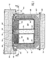
- FIGS. 1 and 2 there is shown schematically an embodiment preferential of a package transport package high activity nuclear devices according to the invention.
- the essential characteristics of this package may be resumed in order to transport others types of hazardous products such as certain products without departing from the scope of the invention.
- the transport packaging shown on the FIG. 1 mainly comprises a body 10, a hood removable shock absorber 12 and a removable shock-absorbing bottom 14.
- the body 10 of the package has a cylindrical shape, centered on an axis intended to be oriented substantially in a vertical direction when transport.
- the peripheral wall and the bottom of the body 10 are materialized by a metal jacket 16, in mechanically welded stainless steel.
- the upper face 17, substantially flat, of the body 10 is materialized in partly by a metal flange 18, also of steel stainless.
- the peripheral edge of this flange 18 is spaced from the upper edge of the shirt 16 and connected to it edge by a deformable sheet 20, also of steel welded.
- the metal flange 18 encircles a disc 19, which has four openings circular. These openings form the passages access to four juxtaposed cells 22, designed to to house four high-level nuclear packages at inside the body 10.
- the cells 22 form cylindrical housings of the same dimensions, whose axes are parallel to the axis of the body 10 and regularly distributed at the same distance from it as shown in Figure 2.
- Each of the cells 22 is delimited by waterproof way by an inner metal shell 24, made of stainless steel.
- This metal envelope interior 24 is formed of a peripheral plate 24a and of a bottom plate 24b welded together by a solder 26 ( Figure 4).
- the upper edge of the Peripheral plate of the inner metal shell 24 is welded to the disk 19.
- Each of the cells 22 is normally closed by a plug 28 individual shutter.
- Each of the plugs 28 is made of a material of protection such as lead, coated with stainless steel.
- a closure plate 30 is attached to the central portion of the disk 19, so as to maintain places the plugs 28 in their closed position.
- the plate of closure 30 is fixed on the flange 18 by a screw 32 disposed along the axis of the body 10.
- a lid 34 completely covers the plugs 28 and the closure plate 30 on the face upper body 10. More specifically ( Figure 3), the lid 34 is fixed by screws 36 on the flange 18 materializing the upper face 17 of the body 10, and it cooperates tightly with this face 17, by three concentric circular seals, which simultaneously encircle all the plugs 28, so to ensure global containment of the cells 22.
- the screws 36 are arranged outside the joints sealing, relative to the axis of the body 10.
- the three seals include a seal outside 38, an intermediate seal 40 and a seal 42.
- the seals 38, 40 and 42 are o-rings that are received in throats concentric formed on the face of the lid 34 intended to be applied against the upper face 17 of the body 10.
- the cover 34 carries a first connection 44, accessible on its upper face, and which opens in an annular space 47 formed between the joint internal sealing 42 and the seal intermediate 40.
- This first connector 44 is intended to be connected to an external source (not shown) a tracer gas under pressure such as helium.
- the lid 34 also carries a second connection 46, accessible from its upper face, which opens into an annular space 48 defined between the intermediate seal 40 and seal outer seal 38.
- This second connector 47 is intended to be connected to external means (no represented) of depressed space ring 48 and tracer gas detection.
- the inner metal shell 24 is doubled by an outer metal shell 50, manufactured in copper.
- the presence of this metal shell outer 50 significantly improves the control of the containment of packages, in relation to existing packaging.
- the outer metal shell 50 also makes it possible to detect a possible leak of the metal casing 24, for example at the level of the welding 26, using connected external devices at connectors 44 and 46. In particular, the presence of the outer metal casing 50 allows determine the defective cell (s).
- third connectors 52 are implanted on the upper face of the body 10, beyond the peripheral edge of the cover 34, by example on the deformable sheet 20.
- Each of the fittings 52 is mounted at a first end of a pipe 54, the opposite end of which is connected to the outer metal casing 50 of the cell 22 corresponding, so as to emerge between this outer metal shell and envelope inner metal 24, close to the weld 26 ( Figure 4).
- Each of the third connectors 52 is provided to be connected to an external source (no shown) of a tracer gas under pressure such as helium.
- outer metal casings 50 made of copper, adjacent cells 22, are connected two to two by sheets 56 of heat dissipation.
- these sheets 56 are made of preferably copper. They extend over the entire height of the outer metal casings 50 and are located approximately on a centered cylinder on the axis of the body 10 of the packaging and tangent externally to the envelopes 50.
- the sheets 56 facilitate evacuation, to the outside of packaging, heat released by packages high-activity nuclear cells housed in the alveoli 22.
- the body 10 of the package has a biological protection 58, lead, which surrounds totally the cells at their periphery and in the body bottom 10.
- This biological protection 58 is separated from the metal jacket 16, which materializes the peripheral wall and the bottom wall of the body 10, by a space filled with concrete 60.
- the central part of body 10 also comprises a concrete core 62, in the region between the cells 22.
- grippers 64 of packaging are mounted on the annular part of the metal jacket 16, materializing the wall body peripheral 10. As shown in Figure 2, these gripping members 64 are placed in planes passing through the axis of the body 10 and located between adjacent cells 22. In case of drop of the packaging on one of the gripping members 64, this provision avoids the rupture of the containment cells 22.
- each of the gripping members 64 is formed of two disjointed metal plates, parallel to the aforementioned plan, including the extreme parts outward facing are partially folded towards each other in relation to this plan, to be welded together at their ends. This configuration accelerates the deformation of the organs of gripping 64 in case of drop of the package. She therefore also helps to avoid any risk of rupture of cell containment 22.
- the hood removable damper 12 is provided to be fixed on the body 10 by screws 66. More specifically, the screws 66 through a flange formed on the metal shirt 16, near its high end, and they are screwed into an outer metal shell of the hood 12.
- the outer casing of the damping hood Removable 12 is filled with stacked balsa. This structure allows the hood to absorb shocks by deforming.
- the damper bottom 14 is fixed so dismountable under the bottom of the body 10, for example at bolts 68.
- bolts 68 simultaneously cross a flange formed in the bottom of the metal jacket 16 and a flange formed in the top of the damper bottom 14.
- the removable shock absorbing bottom 14 is made substantially in the same way as the removable damping cover 12.
- the removable shock absorbing bottom 14 is consisting mainly of a stack of balsa, enclosed in a metal outer casing.
- balsa in which are formed the hood 12 and the bottom 14 can be replaced by nest structures of progressive bees.
- the bottom 14 also performs a function shock absorber.
- the hood 12, the lid 34, the holding plate 30 and the plugs individual 28 are disassembled in turn. We place then in each of the cells 22 one of the packages high-activity nuclear weapons to be transported.
- the leakage rate obtained using the packaging according to the invention is approximately 10 -8 Pa.m 3 / s.
- the control equipment is disassembled and the removable damping hood 12 is put in place. The transport of the packaging can then be carried out.
- each of the connectors 52 to a source of helium, in order to determine the inner metal envelope (s) 24 that are not waterproof.
- the repair may be to do either through the inside of the cell or through outside. In the latter case, disassembly almost total packing is required.
- the addition of the removable damping hood 12 and the Removable damper bottom 14 helps preserve the containment of alveoli in all circumstances accidental. Moreover, if a fall occurs, the body 10 of the package can usually be reused, replacing the hood and / or the bottom damaged by the fall.
- the sheet metal 20 can be deformed and thus helps to preserve the containment of cells 22.
- the shape and arrangement of the grips 64 also make it possible to avoid any risk of confinement of the cells 22 in the event of a fall in packaging on one of these organs.
- the invention is not limited to the embodiment which has just been described.
- the transport packaging according to the invention can be used to transport any dangerous package other than high-level nuclear packages.
- the biological protection of the body 10 and plugs 28 can be removed or modified.
Landscapes
- Physics & Mathematics (AREA)
- Engineering & Computer Science (AREA)
- General Engineering & Computer Science (AREA)
- High Energy & Nuclear Physics (AREA)
- Buffer Packaging (AREA)
- Packages (AREA)
- Examining Or Testing Airtightness (AREA)
Description
- la figure 1 est une vue en coupe verticale qui représente schématiquement un emballage de transport conforme à l'invention ;
- la figure 2 est une vue en coupe selon la ligne II-II de la figure 1 ;
- la figure 3 est une vue à plus grande échelle qui représente un détail de l'emballage ; et
- la figure 4 est une vue en coupe représentant un autre détail de l'emballage selon l'invention.
Claims (15)
- Emballage de transport de colis dangereux, caractérisé par le fait qu'il comprend un corps (10) délimitant intérieurement au moins une alvéole (22) qui débouche sur une même face (17) du corps, des bouchons (28) d'obturation individuelle de chaque alvéole, et un couvercle (34) recouvrant les bouchons et coopérant avec ladite face (17) par des joints d'étanchéité extérieur (38), intermédiaire (40) et intérieur (42) qui encerclent simultanément tous les bouchons, le couvercle étant muni d'un premier raccord (44), apte à être relié à une source de gaz traceur sous pression et débouchant entre les joints d'étanchéité intérieur (42) et intermédiaire (40), et d'un deuxième raccord (46), apte à être relié à des moyens de mise en dépression et de détection du gaz traceur, et débouchant entre les joints d'étanchéité intermédiaire (40) et extérieur (38).
- Emballage selon la revendication 1, dans lequel chaque alvéole (22) est délimitée par une enveloppe métallique intérieure (24) comportant au moins une soudure (26), doublée par une enveloppe métallique extérieure (50).
- Emballage selon la revendication 2, dans lequel le corps (10) est équipé extérieurement de troisièmes raccords (52) aptes à être reliés à une source de gaz traceur sous pression, des tuyauteries (54) reliant chacun des troisièmes raccords (52) à l'enveloppe métallique extérieure (50) de l'une des alvéoles, de façon à déboucher à proximité de ladite soudure (26).
- Emballage selon la revendication 3, dans lequel les troisièmes raccords (52) sont montés sur ladite face (17) du corps (10), au-delà du couvercle (34).
- Emballage selon l'une quelconque des revendications 3 et 4, dans lequel un outillage spécial, apte à être relié à des moyens de mise en dépression et de détection du gaz traceur, peut être monté à la place du couvercle (34).
- Emballage selon l'une quelconque des revendications 2 à 5, dans lequel les enveloppes métalliques extérieures (50) des alvéoles (22) voisines sont reliées les unes aux autres par des tôles (56) de dissipation thermique.
- Emballage selon la revendication 6, dans lequel les enveloppes métalliques extérieures (50) et les tôles (56) de dissipation thermique sont en cuivre.
- Emballage selon l'une quelconque des revendications précédentes, dans lequel un capot amortisseur amovible (12) et un fond amortisseur amovible (14) sont montés respectivement sur ladite face (17) et sur une face opposée du corps.
- Emballage selon la revendication 8, dans lequel le capot amortisseur amovible (12) et le fond amortisseur amovible (14) sont formés, au moins en partie, de balsa empilé.
- Emballage selon la revendication 9, dans lequel le capot amortisseur amovible (12) et le fond amortisseur amovible (14) comprennent également des structures en nids d'abeilles progressives.
- Emballage selon l'une quelconque des revendications précédentes, dans lequel le corps (10) présente une forme cylindrique, d'axe donné, et les alvéoles (22) sont régulièrement réparties autour de cet axe, et dans lequel des organes de préhension (64) de l'emballage sont montés sur une paroi périphérique du corps (10), dans des plans passant par l'axe de ce dernier et situés entre les alvéoles (22).
- Emballage selon la revendication 11, dans lequel les organes de préhension (64) sont au moins partiellement incurvés par rapport aux plans dans lesquels ils sont montés.
- Emballage selon l'une quelconque des revendications 11 et 12, dans lequel ladite face (17) du corps (10) est formée en partie sur une bride métallique (18) qui encercle les alvéoles (22) et sur laquelle est fixé le couvercle (34), la paroi périphérique du corps étant matérialisée par une chemise métallique (16) dont un bord, placé sur ladite face du corps (10), est relié à la bride (18) par une tôle déformable (20).
- Emballage selon l'une quelconque des revendications 11 à 13, dans lequel le corps (10) et les bouchons (28) incluent une protection biologique (58), qui entoure totalement les alvéoles, la protection biologique (58) du corps (10) étant séparée de sa paroi périphérique par un espace rempli de béton (60).
- utilisation d'un emballage selon l'une quelconque des revendications précédentes, pour le transport de colis nucléaires de haute activité.
Applications Claiming Priority (2)
| Application Number | Priority Date | Filing Date | Title |
|---|---|---|---|
| FR9704418 | 1997-04-10 | ||
| FR9704418A FR2762132B1 (fr) | 1997-04-10 | 1997-04-10 | Emballage de transport de colis dangereux, tels que des colis nucleaires de forte activite |
Publications (2)
| Publication Number | Publication Date |
|---|---|
| EP0871180A1 EP0871180A1 (fr) | 1998-10-14 |
| EP0871180B1 true EP0871180B1 (fr) | 2003-09-03 |
Family
ID=9505749
Family Applications (1)
| Application Number | Title | Priority Date | Filing Date |
|---|---|---|---|
| EP98400853A Expired - Lifetime EP0871180B1 (fr) | 1997-04-10 | 1998-04-08 | Emballage de transport de colis dangereux, tels que des colis nucléaires de forte activité |
Country Status (6)
| Country | Link |
|---|---|
| US (1) | US6114710A (fr) |
| EP (1) | EP0871180B1 (fr) |
| JP (1) | JP4149557B2 (fr) |
| DE (1) | DE69817654T2 (fr) |
| ES (1) | ES2206860T3 (fr) |
| FR (1) | FR2762132B1 (fr) |
Families Citing this family (23)
| Publication number | Priority date | Publication date | Assignee | Title |
|---|---|---|---|---|
| RU2179342C1 (ru) * | 2000-12-28 | 2002-02-10 | Громов Сергей Александрович | Комплект для упаковки и транспортировки радиоактивных отходов |
| US6989543B2 (en) | 2003-08-15 | 2006-01-24 | C.R. Bard, Inc. | Radiation shielding container for radioactive sources |
| US7199375B2 (en) * | 2004-10-12 | 2007-04-03 | Bard Brachytherapy, Inc. | Radiation shielding container that encloses a vial of one or more radioactive seeds |
| JP4701187B2 (ja) | 2004-11-30 | 2011-06-15 | パナソニック株式会社 | 画像処理方法、画像処理装置、および画像処理プログラム |
| FR2908227B1 (fr) * | 2006-11-08 | 2009-02-13 | Commissariat Energie Atomique | Dispositif de transport de combustible nucleaire et procede de chargement/dechargement dudit dispositif |
| JP4681681B1 (ja) * | 2010-07-02 | 2011-05-11 | 三菱重工業株式会社 | キャスク用緩衝体 |
| WO2013158914A1 (fr) | 2012-04-18 | 2013-10-24 | Holtec International, Inc. | Stockage et/ou transfert de déchets hautement radioactifs |
| US11373774B2 (en) | 2010-08-12 | 2022-06-28 | Holtec International | Ventilated transfer cask |
| US11887744B2 (en) | 2011-08-12 | 2024-01-30 | Holtec International | Container for radioactive waste |
| CN102467984A (zh) * | 2010-11-19 | 2012-05-23 | 中国辐射防护研究院 | 一种高活度废放射源整备方法及其专用装置 |
| FR2971616B1 (fr) * | 2011-02-11 | 2017-04-07 | Robatel Ind | Capot amortisseur pour emballage de transport et ensemble de transport de matieres radioactives comportant un tel capot amortisseur |
| PL2524705T3 (pl) | 2011-05-19 | 2014-12-31 | Lohmann & Rauscher Gmbh & Co Kg | Sterylne opatrunki ran zawierające syntetyczny elastomer trój-blokowy i hydrofobowy polimer biguanidyny |
| US11515054B2 (en) | 2011-08-19 | 2022-11-29 | Holtec International | Method of retrofitting a spent nuclear fuel storage system |
| US9442037B2 (en) | 2012-08-31 | 2016-09-13 | Holtec International | System and method for storing and leak testing a radioactive materials storage canister |
| CN107077899B (zh) | 2014-10-07 | 2019-11-12 | 霍尔泰克国际公司 | 环境隔离的乏燃料池 |
| US10311989B2 (en) * | 2016-05-26 | 2019-06-04 | Kurion, Inc. | System for storage container with removable shield panels |
| CN106482451B (zh) * | 2016-09-23 | 2022-05-27 | 广东核电合营有限公司 | 乏燃料贮运容器真空干燥及充氦装置 |
| FR3060192B1 (fr) * | 2016-12-09 | 2019-05-17 | Tn International | Emballage de transport et/ou d'entreposage de matieres radioactives comprenant un systeme de communication fluidique ameliore entre l'interieur et l'exterieur de l'enceinte de confinement |
| FR3076057B1 (fr) * | 2017-12-27 | 2020-01-24 | Tn International | Emballage de transport et/ou d'entreposage de matieres radioactives presentant des moyens ameliores de maintien de capot amortisseur |
| US10692618B2 (en) | 2018-06-04 | 2020-06-23 | Deep Isolation, Inc. | Hazardous material canister |
| US10943706B2 (en) | 2019-02-21 | 2021-03-09 | Deep Isolation, Inc. | Hazardous material canister systems and methods |
| US10878972B2 (en) | 2019-02-21 | 2020-12-29 | Deep Isolation, Inc. | Hazardous material repository systems and methods |
| WO2022177862A1 (fr) | 2021-02-16 | 2022-08-25 | Deep Isolation, Inc. | Systèmes et procédés pour bidons de déchets dangereux |
Family Cites Families (8)
| Publication number | Priority date | Publication date | Assignee | Title |
|---|---|---|---|---|
| DE3025795C2 (de) * | 1980-07-08 | 1986-08-28 | GNS Gesellschaft für Nuklear-Service mbH, 4300 Essen | Verfahren zur kontinuierlichen Überwachung von zwei Dichtungsbarrieren bei Abschirmtransport- und Lagerbehältern für radioaktive Substanzen |
| JPS57113341A (en) * | 1980-12-29 | 1982-07-14 | Hitachi Zosen Corp | Leakage inspection for airtightness of radioactive substance conveying container |
| DE3127219A1 (de) * | 1981-07-10 | 1983-01-27 | GNS Gesellschaft für Nuklear-Service mbH, 4300 Essen | Abschirmtransport- und/oder abschirmlagerbehaelter |
| JPS5983096A (ja) * | 1982-11-02 | 1984-05-14 | 木村化工機株式会社 | 放射性物質輸送容器 |
| US4465201A (en) * | 1983-01-28 | 1984-08-14 | The United States Of America As Represented By The United States Department Of Energy | Conical O-ring seal |
| IT1185498B (it) * | 1984-11-13 | 1987-11-12 | Westinghouse Electric Corp | Sistema di chiusura di un fusto per lo stoccaggio di combustibile esaurito |
| FR2649824B1 (fr) * | 1989-07-17 | 1994-03-25 | Commissariat A Energie Atomique | Emballage d'entreposage et de transport de matieres fissiles |
| GB2265675B (en) * | 1992-04-01 | 1995-03-01 | Nirex Uk Ltd | Sealing arrangement |
-
1997
- 1997-04-10 FR FR9704418A patent/FR2762132B1/fr not_active Expired - Lifetime
-
1998
- 1998-04-08 EP EP98400853A patent/EP0871180B1/fr not_active Expired - Lifetime
- 1998-04-08 ES ES98400853T patent/ES2206860T3/es not_active Expired - Lifetime
- 1998-04-08 DE DE69817654T patent/DE69817654T2/de not_active Expired - Lifetime
- 1998-04-09 JP JP09794098A patent/JP4149557B2/ja not_active Expired - Lifetime
- 1998-04-09 US US09/057,692 patent/US6114710A/en not_active Expired - Lifetime
Also Published As
| Publication number | Publication date |
|---|---|
| DE69817654D1 (de) | 2003-10-09 |
| FR2762132A1 (fr) | 1998-10-16 |
| ES2206860T3 (es) | 2004-05-16 |
| JPH10339797A (ja) | 1998-12-22 |
| EP0871180A1 (fr) | 1998-10-14 |
| US6114710A (en) | 2000-09-05 |
| DE69817654T2 (de) | 2004-06-24 |
| FR2762132B1 (fr) | 1999-06-18 |
| JP4149557B2 (ja) | 2008-09-10 |
Similar Documents
| Publication | Publication Date | Title |
|---|---|---|
| EP0871180A1 (fr) | Emballage de transport de colis dangereux, tels que des colis nucléaires de forte activité | |
| EP0473489A1 (fr) | Procédé de contrôle de la mise en place d'un élément transportable et de l'étanchéité de la liaison avec une structure fixe et utilisation de ce procédé | |
| EP1977430B1 (fr) | Élément de stockage de combustible nucléaire empilable et module de stockage formé par un empilement de tels éléments | |
| FR2784785A1 (fr) | Reacteur nucleaire a eau equipe d'un receptacle contenant des structures internes deformables | |
| EP1668650B1 (fr) | Procede et dispositif de conditionnement de crayons de combustible nucleaire non etanches en vue de leur transport et de leur stockage ou entreposage de longue duree | |
| FR2805655A1 (fr) | Conteneur a double enceinte pour le transport ou le stockage de matieres radioactives | |
| EP3042378B1 (fr) | Colis comprenant des moyens ameliores d'amortissement de choc entre un ensemble renfermant des matieres radioactives et le couvercle de l'emballage | |
| EP1344227B1 (fr) | Dispositif de conditionnement, pour le transport en vrac de matieres fissiles uraniferes | |
| EP0283337B1 (fr) | Conteneur de transport aérien pour matières dangereuses | |
| WO2007085586A2 (fr) | Procede et dispositif de fermeture en piscine d'un etui charge avec du combustible nucleaire irradie | |
| EP2656352B1 (fr) | Dispositif de stockage longue duree integrant un etui de stockage ventile destine a recevoir un etui de confinement contenant des matieres radioactives | |
| EP1700315B1 (fr) | Dispositif et procede de conditionnement d'assemblages de combustible nucleaire a double barriere de confinement | |
| WO2003105158A1 (fr) | Procede et installation automatique de confinement etanche et securise de combustible nucleaire use | |
| CH665919A5 (fr) | Dispositif de fermeture de chateau de stockage de combustible nucleaire use. | |
| CH424441A (fr) | Equipement de filtration | |
| EP4315369B1 (fr) | Ensemble pour le transport d'hexafluorure d'uranium, comprenant des capots amortisseurs de choc | |
| FR2649824A1 (fr) | Emballage d'entreposage et de transport de matieres fissiles | |
| EP0988239B1 (fr) | Coffre-conteneur de transport pour objets fragiles et/ou de valeur | |
| FR3121265A1 (fr) | Ensemble pour le transport d’hexafluorure d’uranium | |
| EP0208611A1 (fr) | Conteneur pour déchets radioactifs de moyenne ou faible activité | |
| BE1011152A3 (fr) | Dispositif pour le groupement d'assemblages. | |
| EP0877388A1 (fr) | Dispositif de fermeture étanche d'un boitier de confinement à usages multiples pour assemblages combustibles nucléaires irradiés ou déchets à haute activité | |
| EP0143033A1 (fr) | Conteneur blindé pour le transport et le stockage d'un chargement radioactif | |
| FR2830668A1 (fr) | Installation et dispositif d'entreposage de matieres nucleaires | |
| FR2552519A1 (fr) | Dispositif d'obturation d'une enceinte de confinement |
Legal Events
| Date | Code | Title | Description |
|---|---|---|---|
| PUAI | Public reference made under article 153(3) epc to a published international application that has entered the european phase |
Free format text: ORIGINAL CODE: 0009012 |
|
| AK | Designated contracting states |
Kind code of ref document: A1 Designated state(s): BE CH DE ES GB LI |
|
| AX | Request for extension of the european patent |
Free format text: AL;LT;LV;MK;RO;SI |
|
| 17P | Request for examination filed |
Effective date: 19990319 |
|
| AKX | Designation fees paid |
Free format text: BE CH DE ES GB LI |
|
| 17Q | First examination report despatched |
Effective date: 20010730 |
|
| GRAH | Despatch of communication of intention to grant a patent |
Free format text: ORIGINAL CODE: EPIDOS IGRA |
|
| GRAH | Despatch of communication of intention to grant a patent |
Free format text: ORIGINAL CODE: EPIDOS IGRA |
|
| GRAA | (expected) grant |
Free format text: ORIGINAL CODE: 0009210 |
|
| AK | Designated contracting states |
Kind code of ref document: B1 Designated state(s): BE CH DE ES GB LI |
|
| REG | Reference to a national code |
Ref country code: GB Ref legal event code: FG4D Free format text: NOT ENGLISH |
|
| REG | Reference to a national code |
Ref country code: CH Ref legal event code: EP |
|
| REF | Corresponds to: |
Ref document number: 69817654 Country of ref document: DE Date of ref document: 20031009 Kind code of ref document: P |
|
| GBT | Gb: translation of ep patent filed (gb section 77(6)(a)/1977) |
Effective date: 20031219 |
|
| REG | Reference to a national code |
Ref country code: ES Ref legal event code: FG2A Ref document number: 2206860 Country of ref document: ES Kind code of ref document: T3 |
|
| PLBE | No opposition filed within time limit |
Free format text: ORIGINAL CODE: 0009261 |
|
| STAA | Information on the status of an ep patent application or granted ep patent |
Free format text: STATUS: NO OPPOSITION FILED WITHIN TIME LIMIT |
|
| 26N | No opposition filed |
Effective date: 20040604 |
|
| PGFP | Annual fee paid to national office [announced via postgrant information from national office to epo] |
Ref country code: CH Payment date: 20170424 Year of fee payment: 20 Ref country code: DE Payment date: 20170412 Year of fee payment: 20 Ref country code: GB Payment date: 20170420 Year of fee payment: 20 |
|
| PGFP | Annual fee paid to national office [announced via postgrant information from national office to epo] |
Ref country code: BE Payment date: 20170425 Year of fee payment: 20 Ref country code: ES Payment date: 20170508 Year of fee payment: 20 |
|
| REG | Reference to a national code |
Ref country code: DE Ref legal event code: R071 Ref document number: 69817654 Country of ref document: DE |
|
| REG | Reference to a national code |
Ref country code: CH Ref legal event code: PL |
|
| REG | Reference to a national code |
Ref country code: GB Ref legal event code: PE20 Expiry date: 20180407 |
|
| REG | Reference to a national code |
Ref country code: BE Ref legal event code: MK Effective date: 20180408 |
|
| PG25 | Lapsed in a contracting state [announced via postgrant information from national office to epo] |
Ref country code: GB Free format text: LAPSE BECAUSE OF EXPIRATION OF PROTECTION Effective date: 20180407 |
|
| REG | Reference to a national code |
Ref country code: ES Ref legal event code: FD2A Effective date: 20200803 |
|
| PG25 | Lapsed in a contracting state [announced via postgrant information from national office to epo] |
Ref country code: ES Free format text: LAPSE BECAUSE OF EXPIRATION OF PROTECTION Effective date: 20180409 |