EP0871977B1 - Procede de reduction d'intensites ioniques selectionnees dans des faisceaux ioniques confines - Google Patents
Procede de reduction d'intensites ioniques selectionnees dans des faisceaux ioniques confines Download PDFInfo
- Publication number
- EP0871977B1 EP0871977B1 EP97903735A EP97903735A EP0871977B1 EP 0871977 B1 EP0871977 B1 EP 0871977B1 EP 97903735 A EP97903735 A EP 97903735A EP 97903735 A EP97903735 A EP 97903735A EP 0871977 B1 EP0871977 B1 EP 0871977B1
- Authority
- EP
- European Patent Office
- Prior art keywords
- ions
- ion
- carrier gas
- analyte
- hydrogen
- Prior art date
- Legal status (The legal status is an assumption and is not a legal conclusion. Google has not performed a legal analysis and makes no representation as to the accuracy of the status listed.)
- Expired - Lifetime
Links
Images



Classifications
-
- H—ELECTRICITY
- H01—ELECTRIC ELEMENTS
- H01J—ELECTRIC DISCHARGE TUBES OR DISCHARGE LAMPS
- H01J49/00—Particle spectrometers or separator tubes
- H01J49/02—Details
- H01J49/10—Ion sources; Ion guns
- H01J49/14—Ion sources; Ion guns using particle bombardment, e.g. ionisation chambers
- H01J49/145—Ion sources; Ion guns using particle bombardment, e.g. ionisation chambers using chemical ionisation
Definitions
- the present invention relates generally to a method for producing an ion beam having an increased proportion of analyte ions compared to carrier gas ions. More specifically, the method has steps resulting in selectively neutralizing carrier gas ions. Yet more specifically, the method has the step of addition of a charge transfer gas to the carrier analyte combination that accepts charge from the carrier gas ions yet minimally accepts charge from the analyte thereby selectively neutralizing the carrier gas ions.
- ion beams are used in ion guns, ion implanters, ion thrusters for attitude control of satellites, laser ablation plumes, and various mass spectrometers (MS), including linear quadrupole MS, ion trap quadrupole MS, ion cyclotron resonance MS, time of flight MS, and electric and/or magnetic sector MS.
- MS mass spectrometers
- Several schemes are known in the art for generating such ion beams including electron impact, laser irradiation, ionspray, electrospray, thermospray, inductively coupled plasma sources, glow discharges and hollow cathode discharges.
- Typical arrangements combine the analyte with a carrier or support gas whereby the carrier gas is utilized to aid in transporting, ionizing, or both transporting and ionizing, the analyte.
- an analyte is combined with the carrier gas in an electrical field, whereupon the analyte and the carrier gas are ionized in a strong electric or magnetic field and later used in an analytical or industrial process.
- the carrier gas is first ionized in a strong electric or magnetic field whereupon the analyte is then introduced into the ionized carrier gas.
- Electric fields are generated by a variety of methods well known in the art including, but not limited to, capacitive and inductive coupling.
- a radio frequency (RF) voltage is applied to a coil of a conducting material, typically brass.
- a carrier gas such as argon
- an analyte which may be any substance.
- the analyte may be supplied in a variety of forms including but not limited to a gaseous form, as a liquid, as a droplet form as in an aerosol, or as a laser ablated aerosol.
- a large electrical field is generated within the coil. Within this field, any free electrons will initiate a chain reaction in the analyte and the carrier gas causing a loss of electrons and thus ionization of the carrier gas and the analyte.
- both the carrier gas and the analyte in the plasma may be in the form of particles, atoms or molecules, or a mixture of particles, atoms and molecules, depending on the particular species selected for use as the carrier gas and analyte.
- the carrier gas and the analyte may be combined by a wide variety of methods well known in the art.
- the analyte and the carrier gas in an aerosol form are combined and are then directed to the interior of a coil in an inductively coupled plasma.
- Another typical arrangement employs a needle which receives a liquid sample of analyte from a source such as a liquid chromatograph.
- a source such as a liquid chromatograph.
- a tube which supplies a carrier gas such as argon as a high velocity atomizing carrier gas.
- Both the needle and the tube empty into a chamber. Upon discharge from the needle, the analyte liquid is evaporated and atomized in the argon carrier gas.
- Ions of both the evaporated liquid analyte and the argon carrier gas are produced by creating an electric field within the chamber.
- the electric field may be produced by creating a voltage difference between the needle and the chamber.
- a voltage difference may be created by applying a voltage to the needle and grounding the chamber.
- the resultant plasma generated by any of the foregoing methods is typically directed towards either an analytical apparatus or towards a reaction zone wherein the carrier gas and analyte ions are analyzed or otherwise reacted or utilized in some fashion.
- the resultant plasma is typically directed by means of an electric or magnetic field, or by means of a pressure differential, or both.
- the plasma is converted from a plasma to an ion beam.
- ion beam refers to a stream consisting primarily of positively charged and neutral species.
- the bulk of the negatively charged species in the plasma are typically electrons, which are rapidly dispersed as the plasma is directed by either electric or magnetic fields or by a pressure differential.
- the ion beam may not be completely void of negatively charged species.
- the free electrons due to their low mass relative to the positively charged ions, tend to disperse from the plasma, thus converting the plasma to an ion beam.
- the ion beam itself will tend to disperse due to several effects. Most prominent among these effects is the repulsive forces of charged species within the ion beam.
- the beam is also dispersed through free jet expansion. The effect of dispersion of the constituent species in the ion beam is charge separation among those species and is well known in the art.
- the resultant ion beam is thus typically characterized by high net positive charge density which is primarily attributable to the relatively high abundance of positively charged carrier gas ions.
- the abundance of positively charged carrier gas ions and/or the resultant high charge density may be undesirable.
- the ion beam be focused through a small aperture, for example, if the analyte ions were to be analyzed in a mass spectrometer.
- the high charge density will prescribe a space charge limit to the amount of the ion beam that may be passed through a given aperture.
- the space charge limit is reached, the remainder of the beam is unable to pass through the aperture and is thus lost.
- the portion of the beam which is lost includes analyte ions.
- a loss of a portion of the beam may result in a disproportionate loss of some or all of the analyte ions because the analyte ions may not be evenly distributed throughout the ion beam or may not respond to the various dispersing forces in the same manner as the carrier gas ions.
- ion trap mass spectrometer where the ion trap has a limited ion storage capacity.
- the carrier gas ions compete with analyte ions for the limited storage capacity of the ion trap.
- the storage capacity for analyte ions in the ion trap is thereby increased.
- a third example where the presence of carrier gas ions is undesirable is any application where the analyte ions are to be used in a process or reaction where the carrier gas ions might interfere with such process.
- ion beams may be directed towards a targeted material such as a silicon wafer to impart electrical or physical properties to the material.
- the desired properties are typically highly dependent on the specific ions directed at such materials.
- carrier gas ions may cause undesirable effects in the targeted materials.
- US-A-5,120,956 discloses an accelerator mass spectrometer in which a stripper within a high voltage terminal converts negative analyte ions into a positive charge state, and induces dissociation of all background molecules.
- US-A-5,396,064 discloses a method and apparatus for isolating a single ion species of interest in a quadruple ion trap (QIT).
- QIT quadruple ion trap
- US-A-4,948,962 discloses a plasma ion source mass spectrometer in which a gas additive is used to quench background ions or excited molecules, thereby to enhance the sensitivity of the spectrometer to analyte ions.
- US-A-5,049,739 discloses a plasma ion source mass spectrometer in which fast disturbing ions contained in the incident ion beam are transformed into fast neutral atoms or molecules and slow the disturbing ions by a resonance charge exchange reaction.
- the invention provides a method for producing an ion beam with increased proportion of analyte ions and a corresponding decreased number of carrier gas ions by neutralizing carrier gas ions while minimally removing or neutralizing the analyte ions. This is accomplished by providing the ion beam at a desired kinetic energy and directing the ion beam through a volume of a reagent gas comprising hydrogen thereby allowing the carrier gas to selectively transfer charge from carrier gas ions to hydrogen in the reagent gas, thereby rendering the hydrogen gas a charged species and the carrier gas a neutral species.
- selective means that the transfer of charge from the carrier gas ions to the hydrogen gas proceeds at a rate at least ten times, and preferably over one thousand times, the rate of the transfer of charge from the analyte gas ions to the hydrogen gas. After this charge transfer, the charged hydrogen in the reagent gas is then selectively dispersed, leaving an ion beam having a greater fraction of analyte ions to total ions.
- analyte ions refers to any ions generated by any means including but not limited to thermal ionization, ion beams, electron impact ionization, laser irradiation, ionspray, electrospray, thermospray, inductively coupled plasmas, microwave plasmas, glow discharges, arc/spark discharges and hollow cathode discharges.
- reagent gas refers to any gas comprising hydrogen suitable for accepting charge transfer to hydrogen by any means, including but not limited to commercially available substance provided in gaseous form and mixtures thereof and gases. generated by evaporation of condensed substances or laser ablation of condensed substances.
- reagent gas as used herein may include neutral species of analyte ions generated by any of the foregoing methods.
- the method of the present invention is not limited to systems containing a carrier gas per se.
- the two gas species are an analyte and a carrier gas.
- the method of the present invention will work equally well in any system having two or more ion species, even if none of the species were provided as a carrier gas.
- suitable reagents may be selected to remove or neutralize those daughter ions by charge transfer.
- a particular analyte may contain a substance of interest in mixture with a separate interfering substance.
- suitable reagents may be selected to remove or neutralize the separate interfering substance by charge transfer.
- the carrier gas selected is argon and the reagent gas selected is hydrogen. Accordingly, it is an object of the invention in one of its aspects to provide a method for selectively reducing the charge density of an ion beam by neutralizing the ions of an argon carrier gas, without eliminating or neutralizing the analyte ions. This is accomplished by directing the ion beam through a volume of hydrogen at kinetic energies wherein the argon ions selectively transfer charge to the hydrogen.
- ICP/MS inductively coupled plasma mass spectrometers
- An ICP/MS is a device wherein a plasma consisting of a carrier gas (typically argon) and an analyte is generated in an inductively coupled plasma (ICP) and a mass spectrometer is employed to separate and distinguish constituent atoms and isotopes.
- ICP inductively coupled plasma
- the ICP is typically operated at atmospheric pressure.
- ion discriminating unit refers to any apparatus which separates charged species according to their m/z and/or kinetic energy.
- Ion discriminating units include but are not limited to a linear quadrupole, an ion trap, a time-of-flight tube, a magnetic sector, an electric sector, a combination of a magnetic sector and an electric sector, a lens stack, a DC voltage plate, an rf/dc multipole ion guide, and an rf multipole ion guide.
- Modified ICP/MS systems have been built which use a three dimensional RF quadrupole ion trap, either alone or in combination with a linear RF quadrupole as an ion discriminating unit. Upon exiting the lens stack, the ion beam is directed into the ion discriminating unit.
- Ions are selectively emitted from the ion discriminating unit according to their mass to charge ratio (m/z) and/or kinetic energy. These selectively emitted ions are then directed to a charged particle detector. In this manner, the ICP/MS is able to determine the presence of selected ions in an analyte according to their (m/z) and/or kinetic energy. It is critical to maintain the ion discriminating unit in a vacuum because collisions or reactions between the ions and any gases present in the ion discriminating -unit will tend to deflect ions away from the charged particle detector or neutralize the ions of analyte.
- ICP/MS systems typically employ apertures between approximately 0.5 mm to approximately 2 mm.
- the reagent gas comprising hydrogen is introduced within an ion beam having a carrier gas and an analyte to allow the charge of the carrier gas ions to be transferred to hydrogen in the reagent gas, whereupon the now charged hydrogen gas may be selectively dispersed from the ion beam.
- the extent of reaction or completeness of this charge transfer will be driven by at least four factors. First, any two species selected will have an inherent rate of reaction which will affect the completeness of charge transfer over a given period of time, all other things held constant. Second, lower velocities of the carrier gas ions will provide a longer residence time for carrier gas ions in the reaction zone and thereby provide a greater extent of reaction.
- the completeness of charge transfer in a given time period is increased as the probability of a collision between carrier gas ions and reagent gas species is increased. Therefore, the completeness of charge transfer is dependent upon the pressure of the reagent gas and the time that the two gases are in contact. If the reagent gas species is present at low concentration or pressure, the carrier gas ions must have sufficient opportunities to come into contact with the reagent gas, i.e., a long residence time must be employed.
- the present invention has been described as employed in an ICP/MS, the method of the present invention may be advantageously applied in any system having a carrier gas and an analyte gas where it is desired to remove or neutralize the carrier gas ions.
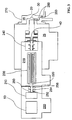
- a conventional ICP/MS manufactured by VG Elemental, now Fisons (Winsford, Cheshire, England; model PQ-I) was modified by replacing the linear quadrupole and its associated electronics (not shown) with an RF quadrupole ion trap 10 and its associated electronics (not shown).
- the ion trap 10 was installed with the ion input and output ends reversed to maximize the ion transfer efficiency from the lens stack 60 into the ion trap 10 .
- the ion trap 10 used was removed from an ion trap mass spectrometer manufactured by Finnigan MAT (San Jose, California).
- the electron gun (not shown) and injection gate electrode assembly (not shown) were removed to allow transfer of ions from the lens stack 60 into the ion trap 10 .
- the vacuum system was modified from a standard Fisons vacuum system and consisted of three vacuum regions separated by two apertures. These vacuum regions are evacuated by standard vacuum pumps (not shown).
- the first vacuum region 15 is contained in between a first aperture 20 and second aperture 30 and is typically operated at 13 Pa to 1.3 kPa (0.1 to 10 Torr).
- the second vacuum region 25 is contained between the second aperture 30 and a third aperture 40 and is typically operated at 1.3 milli Pa to 0.13 Pa (10 -5 to 10 -3 Torr).
- the third aperture 40 is located within the lens stack 60 at substantially the same position as employed in the standard Fisons ICP.MS.
- the third vacuum region 35 is separated from the second vacuum region 25 by the third aperture 40 .
- the third vacuum region 35 contains a portion of the lens stack 60 , the ion trap 10 and a charged particle detector 50 .
- the third vacuum region 35 is typically operated 1.3 micro Pa to 0.13 Pa (10 -8 to 10 -3 Torr).
- FIG. 1 A series of experiments was performed utilizing the apparatus described in the first preferred embodiment.
- the configuration of the various components is shown in FIG. 1 .
- the vacuum regions 15,25,35 were operated under conventional conditions as described above.
- the potentials applied to the lens stack 60 were within the ranges recommended by the manufacturer of the ICP/MS (Fisons).
- the first and second apertures 20,30 were both grounded.
- the third aperture 40 was biased at a DC potential of about -120 V.
- the potentials on the lens stack plates 70,80 were optimized for maximum transfer efficiency of ions into the ion trap 10 and were different than the potentials used in conventional ICP/MS instruments. Ions are gated into the ion trap 10 by switching the potential on plate 80 in the lens stack 60 .
- the potentials on plate 80 were switched between a negative value used to admit ions into the ion trap 10 , in the range between about -10 V to about - 500 V, preferably -35 V, and a positive value used to prevent ions from entering the ion trap 10 , in the range between about +10 V to about +500 V, preferably above +10 V, or the kinetic energy of the ions.
- the electronic gating control (not shown) used for switching the voltage on plate 80 was provided by inverting the standard signal provided by the Finnigan MAT ITMS to gate electrons. This inversion was accomplished using an extra inverter (not shown) on the printed circuit board (not shown) that performs the gating.
- the ion trap 10 is manufactured with a port 90 typically used for introduction of a buffer gas such as helium.
- a buffer gas such as helium.
- Reagent gases were introduced into the ion trap 10 by adding the reagent gases to the helium.
- Typical helium buffer gas pressures were in the range between about 1.3 milli Pa to 0.13 Pa (10 -5 and 10 -3 Torr).
- Reagent to buffer gas pressure ratios ranged between about 0.01% to 100%.
- Ar, H 2 , Xe, or Kr were introduced as reagent gases into the ion trap 10 .
- a conventional ICP/MS manufactured by VG Elemental, now Fisons (Winsford, Cheshire, England; model PQ-I) was modified by interposing an RF quadrupole ion trap 210 between the linear quadrupole 200 and the charged particle detector 50 .
- the electrodes (not shown) used in the ion trap 210 were custom built to be scaled versions of the ITMS electrodes manufactured by Finnigan MAT (San Jose, California), standard ion trap electrodes would work equally well.
- the electrodes of the custom built ion trap 210 were 44% larger than the electrodes of the Finnigan MAT ITMS and were assembled in a pure quadrupole, or un-stretched geometry.
- the standard ITMS electronics package (not shown) manufactured by Finnigan MAT was used with the modifications as described in the first preferred embodiment using the voltages as described below.
- the standard lens stack 240 is operated at potentials recommended by the manufacturer.
- a second lens stack 250 is Finnigan MAT ITMS and were assembled in a pure quadrupole, or un-stretched geometry.
- the standard ITMS electronics package (not shown) manufactured by Finnigan MAT was used with the modifications as described in the first preferred embodiment using the voltages as described below.
- the standard lens stack 240 is operated at potentials recommended by the manufacturer.
- a second lens stack 250 is interposed between the third aperture 220 and the ion trap 210 in the fourth vacuum region 230 .
- the second lens stack 250 consisted of three plates 252,254,256 taken from standard Fisons lens stacks, specifically two L3 plates and an L4 plate.
- the second lens stack 250 was fabricated to provide high ion transport efficiency between the linear quadrupole 200 and the ion trap 210 .
- a potential of between about -10 V and about -300 V, preferrably about -30 V were applied to plates 252,256 at each end of the second lens stack 250 .
- the center plate 254 was used to gate ions into the ion trap 210 and the potential applied was varied between about -180 V for the open potential and about +180 volts for the closed potential.
- the electronic gating control (not shown) used for the center plate 254 of the second lens stack 250 was provided by inverting the standard signal provided by the Finnigan MAT ITMS to gate electrons. This inversion was accomplished using an extra inverter (not shown) on the printed circuit board (not shown) that performs the gating.
- the vacuum system was the standard Fisons system consisting of four vacuum regions separated by three apertures with an additional pump on the fourth vacuum region 230 . These vacuum regions are evacuated by standard vacuum pumps (not shown).
- the first vacuum region 15 is contained in between a first aperture 20 and second aperture 30 and is typically operated at 13 Pa to 1.3 kPa (0.1 to 10 Torr).
- the second vacuum region 25 is contained between the second aperture 30 and a third aperture 40 and is typically operated at 1.3 milli Pa to 0.13 Pa (10 -5 to 10 -3 Torr).
- the third aperture 40 is located within the lens stack 240 .
- the third vacuum region 215 is contained between the third aperture 40 and the fourth aperture 220 and is typically operated at 1.3 micro Pa to 13 milli Pa (10 -8 to 10 -4 Torr).
- the third vacuum region 215 contains the linear quadruple 200 .
- the fourth vacuum region 230 is separated from the third vacuum region 215 by the fourth aperture 220 .
- the fourth vacuum region 230 contains the ion trap 210 and a charged particle detector 50 .
- the fourth vacuum region 230 is typically operated at 1.3 m Pa to 0.13 Pa (10 -8 to 10 -3 Torr).
- a 1.6 mm (1/16") diameter metal tube 260 was provided to allow the introduction of reagent gases into the second vacuum region 25 through two ports 280 provided in the housing 270 surrounding the first vacuum region 15 .
- the tube 260 was fashioned into a shape so as to avoid electrical contact with the lens stack 240 and to position the end of the tube 260 approximately 1 cm behind the base of the second aperture 30 and approximately 1 cm from the central axis defined by the four apertures 20,30,40,220. In this way, reagent gases are introduced into the second vacuum region 25 as close to the second aperture 30 as possible without interfering with the gas dynamics of the sampled plasma and with minimal distortion of the electric field generated by the lens stack 240 .
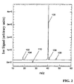
- the values in the second column under the heading "H 2 " show that as the H 2 pressure is increased, the Ar + ion intensity falls about 10 times faster than the In + ion intensity, confirming the selective removal of carrier gas ions.
- Relative Reaction Rates of Carrier Gas Ions and Analyte Ions with Reagent Gases (Ar and Ar/Xe/Kr are comparative examples).
- a conventional ICP/MS manufactured by VG Elemental, now Fisons (Winsford, Cheshire, England; model PQ-II+) was modified by providing 1.6 mm (1/6") diameter metal tube 260 to allow the introduction of reagents into the second vacuum region 25 in a manner identical to the second preferred embodiment.
- the remainder of the ICP/MS was not modified from that provided by the manufacturer.
- a series of experiments was performed utilizing an argon carrier gas and H 2 as a reagent gas introduced via tube 260 into the second vacuum region 25 . Mass spectra were obtained for H 2 pressure in the second vacuum region 25 between zero and 0.26 Pa (about 2 mTorr) and are summarized below.
- the effect of H 2 pressure on the analyte and ion signals were observed by recording the mass spectrum in both the analog and pulse counting modes of operation of the ICP/MS as provided by the manufacturer.
- Two mass spectra recorded without addition of H 2 into the second vacuum region 25 are shown in FIG. 5 .
- the upper trace 500 in FIG. 5 was obtained using the analog mode of operation.
- the lower trace 510 in FIG. 5 was obtained using the pulse counting mode of operation.
- the upper trace 500 shows the intensity of various peaks, most notably, N + at m/z 14 502, O + at m/z 16 504, OH + at m/z 17 506, H 2 O + at m/z 18 508 , Ar + at m/z 40 512, ArH + at m/z 41 514 ,H 2 + at m/z 2 516 , and H 3 + at m/z 3 518 .
- Two mass spectra recorded with addition of a pressure of 0.26 Pa (about 2 mTorr) H 2 into the second vacuum region 25 are shown in FIG. 6.
- the upper trace 600 in FIG. 6 was obtained using the analog mode of operation.
- the lower trace 610 in FIG. 6 was obtained using the pulse counting mode of operation.
- FIG. 5 and FIG. 6 The vertical and horizontal scales of FIG. 5 and FIG. 6 are the same.
- the same ion peaks are labeled in FIG. 6 as in FIG. 5 , namely, N + at m/z 14 602 , O + at m/z 16 604 , OH + at m/z 17 606 , H 2 O + at m/z 18 608 ., Ar + at m/z 40 612 , ArH + at m/z 41 614 ,H 2 + at m/z 2 616 , and H 3 + at m/z 3 618 .
- this method of implementation allows the direct detection of H 3 + produced in the reaction of Ar + with H 2 .
- the formation of this ion is strongly inferred from the experiments performed in the apparatuses of the first two embodiments, but H 3 + could not be detected using the Finnigan MAT ion trap mass spectrometers.
- this method produces a mass spectrum in the same way as a conventional ICP/MS instrument, polyatomic ions which are commonly observed in conventional ICP/MS, but not by using the methods of the first and second preferred embodiments, may also be observed here.
- the effect of elevated H 2 pressures in vacuum region 25 on Ar + may be observed along with the effects on ArO + and Ar 2 + .
- H 2 The most dramatic effect of added H 2 is an approximately 200-fold increase in the intensity of the H 3 + peak 618 .
- Addition of H 2 also causes an approximately 10-fold decrease in the intensity of the Ar + peak 612 and an approximately 2-fold increase in the intensity of the ArH + peak 614 .
- These mass spectra show minimal reduction (less than 10%) in the intensity of the peaks for other analytes (not shown). These mass spectra thus show a selective removal of Ar + and an increase in H 3 + thereby confirming the mechanism of charge transfer in the reaction of H 2 with Ar + .
- H 2 was introduced as a reagent gas into the second vacuum region 25 via the vacuum port 400 provided by the manufacturer for pressure measurements. H 2 pressures ranged from about 13 milli Pa to 0.13 Pa (about 0.1 mTorr to about 1 mTorr).
- the measured Ar+ intensity was reduced by a factor of two with the introduction of the H 2 reagent gas, demonstrating that introduction of H 2 into the second vacuum region 25 of an unmodified ICP/MS can be used to reduce the Ar + ion intensity.
- Table II contains selected data from the experiments performed using the apparatus of the first, second, and third preferred embodiments described herein. Each row of the table gives reduction factors for Ar + and an analyte ion as well as the ratio of these reduction factors. The ratio is the selectivity with which the Ar + intensity in the mass spectrum is reduced relative to the intensity of the analyte ion.
- the entries in the first column in Table II lists the preferred embodiment used to obtain the data given in each row.
- the second column in Table II lists the reagent gas used. The reagent gas was introduced into the ion trap 20 for the results shown in Table II for the first preferred embodiment above. The reagent gas was introduced in vacuum region 25 for the results shown in Table II for the second and third embodiments.
- the third row in Table II shows that the reaction of the carrier gas ion (Ar + ) leads to a 30-fold reduction in Ar + intensity under conditions that reduce the intensity of Sc + by a factor of two.
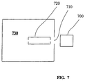
- carrier gas ions and analyte ions generated from an ion source 700 are directed through a first aperture 710 to a cell 720 where the ions are allowed to react with a reagent gas.
- Suitable ion sources include, but are not limited to thermal ionization sources, electron impact, laser irradiation, ion spray, electrospray, thermospray, inductively coupled plasma sources; arc/spark discharges, glow discharges, hollow cathode discharges and microwave plasma sources.
- the cell is contained within a first vacuum region 730 .
- the cell 720 confines ions in a region close to the aperture 710 through which the ions are introduced into the first vacuum region 730 . In this manner, ions are directed from the ion source 700 to the cell 720 with minimum opportunity for ion dispersion.
- the first vacuum region 730 is made to contain the optimal pressure of reagent gas which allows both ion transport through the cell 720 and sufficient charge transfer between the carrier gas ions and the reagent gas.
- the cell 720 also can be made to control the kinetic energy of the ions.
- the cell 720 can be used to increase the residence time the carrier gas ions are in contact with the reagent gas and thus to increase the extent of charge transfer.
- the cell 720 can be made to discriminate against, i.e., not transmit, slow ions by application of velocity or kinetic energy discriminating methods, such as the application of suitable DC electric fields. In this manner, charge exchange between fast carrier gas ions and slow reagent gas neutrals can be used to remove selected carrier gas ions from the ion beam.
- the kinetic energy of the ions in the cell 720 is maintained as high as possible so as to minimize space charge expansion of the ions, but low enough for a given pressure of reagent gas to allow sufficient charge transfer.
- the optimal pressure of the reagent gas will be limited by acceptable analyte ion scattering losses in the cell and practical considerations such as pumping requirements.
- the fourth preferred embodiment may be operated using argon as the carrier gas.
- the cell 720 may be provided as any apparatus suitable for confining the ions in the first vacuum region 730, including but not limited to, an ion trap, a long flight tube, a lens stack or an RF multipole ion guide.
- the cell 720 may be operated to selectively disperse reagent gas ions from the ion beam.
- a reagent gas having a low mass, i.e. H 2 the RF multipole ion guide may be operated with a low mass cut-off greater than m/z 3. In this manner, H 2 + and H 3 + , which are formed as charge transfer products, are selectively dispersed from the ion beam by virtue of their low m/z.
- the resultant ion beam may then be utilized as one of any number of end uses including but not limited to an ion gun or an ion implanter. Further, the resultant beam may be analyzed in various apparatus including but not limited to an optical spectrometer, mass spectrometers (MS), including linear quadrupole MS, ion trap quadrupole MS, ion cyclotron resonance MS, time of flight MS, and magnetic and/or electric sector MS. Finally, the resultant ion beam may be directed through any electrical or magnetic ion focusing or ion directing apparatus, including but not limited to, a lens stack, an RF multipole ion guide, an electrostatic sector, or a magnetic sector.
- a lens stack including but not limited to, a lens stack, an RF multipole ion guide, an electrostatic sector, or a magnetic sector.
- the resultant ion beam thus has an increased proportion of analyte ions compared to carrier gas ions.
- the increased proportion of analyte ions compared to carrier gas ions directed into the aperture will create an increase in the rate at which the analyte ions pass through the aperture.
Landscapes
- Physics & Mathematics (AREA)
- Engineering & Computer Science (AREA)
- Plasma & Fusion (AREA)
- Chemical & Material Sciences (AREA)
- Analytical Chemistry (AREA)
- Other Investigation Or Analysis Of Materials By Electrical Means (AREA)
- Electron Tubes For Measurement (AREA)
- Electron Sources, Ion Sources (AREA)
- Analysing Materials By The Use Of Radiation (AREA)
- Physical Vapour Deposition (AREA)
- Crystals, And After-Treatments Of Crystals (AREA)
Claims (9)
- Méthode améliorée pour fournir un faisceau d'ions dans un système où un mélange d'ions d'un gaz vecteur et d'ions de substance à analyser est fourni, dans laquelle l'amélioration comprend :a) l'exposition dudit mélange à un gaz réactif comprenant de l'hydrogène etb) le transfert sélectif de la charge des ions du gaz vecteur à l'hydrogène, neutralisant ainsi les ions du gaz vecteur et formant de l'hydrogène chargé.
- Méthode de la revendication 1 comprenant également l'étape de l'élimination sélective de l'hydrogène chargé du faisceau d'ions.
- Méthode de la revendication 2 comprenant également l'étape de la prévision d'une unité de discrimination d'ions (10, 210, 240, 250, 720) pour enlever sélectivement l'hydrogène chargé du faisceau d'ions.
- Méthode de la revendication 3 dans laquelle l'unité de discrimination d'ions prévue est sélectionnée parmi le groupe comprenant un quadrupôle linéaire, un piège à ions (10), un tube temps de vol, un secteur magnétique, un secteur électrique, une combinaison d'un secteur magnétique et d'un secteur électrique, une pile de lentilles (240, 250), une plaque de tension c.c., un guide d'ions multipolaire rf (720) et un guide d'ions multipolaire rf/c.c.
- Méthode de la revendication 1 dans laquelle les ions du gaz vecteur sont tirés du groupe de gaz vecteurs consistant en He, Ne, Ar, Kr, Xe et en des combinaisons de ceux-ci.
- Méthode de la revendication 1 dans laquelle l'hydrogène est sous une forme sélectionnée parmi le groupe consistant en H2, D2, HD et en des combinaisons de ceux-ci.
- Méthode de la revendication 1 dans laquelle les ions de substance à analyser sont fournis par une méthode sélectionnée parmi le groupe consistant en l'ionisation thermique, les faisceaux d'ions, l'ionisation par impact électronique, l'irradiation par laser, la nébulisation ionique, l'électronébulisation, la thermonébulisation, les plasmas inductifs, les plasmas produits par micro-ondes, les décharges luminescentes, les décharges d'arcs/d'étincelles, les décharges à cathode creuse, les gaz produits par évaporation de substances condensées, l'ablation par laser des substances condensées et en des mélanges de ces méthodes.
- Méthode de la revendication 1 dans laquelle le mélange des ions du gaz à analyser et des ions du gaz vecteur est fourni par un spectromètre de masse à plasma inductif.
- Méthode de la revendication 1 dans laquelle le gaz réactif comprend également un groupe de gaz consistant en N2, He, Ne, Ar, Kr, Xe et en des combinaisons de ceux-ci.
Priority Applications (1)
| Application Number | Priority Date | Filing Date | Title |
|---|---|---|---|
| EP04002513A EP1465233A2 (fr) | 1996-01-05 | 1997-01-03 | Méthode de réduction d' intensités sélectionnées dans des faisceaux d' ions confinés. |
Applications Claiming Priority (3)
| Application Number | Priority Date | Filing Date | Title |
|---|---|---|---|
| US08/583,324 US5767512A (en) | 1996-01-05 | 1996-01-05 | Method for reduction of selected ion intensities in confined ion beams |
| US583324 | 1996-01-05 | ||
| PCT/US1997/000023 WO1997025737A1 (fr) | 1996-01-05 | 1997-01-03 | Procede de reduction d'intensites ioniques selectionnees dans des faisceaux ioniques confines |
Related Child Applications (1)
| Application Number | Title | Priority Date | Filing Date |
|---|---|---|---|
| EP04002513A Division EP1465233A2 (fr) | 1996-01-05 | 1997-01-03 | Méthode de réduction d' intensités sélectionnées dans des faisceaux d' ions confinés. |
Publications (2)
| Publication Number | Publication Date |
|---|---|
| EP0871977A1 EP0871977A1 (fr) | 1998-10-21 |
| EP0871977B1 true EP0871977B1 (fr) | 2004-05-19 |
Family
ID=24332634
Family Applications (2)
| Application Number | Title | Priority Date | Filing Date |
|---|---|---|---|
| EP04002513A Withdrawn EP1465233A2 (fr) | 1996-01-05 | 1997-01-03 | Méthode de réduction d' intensités sélectionnées dans des faisceaux d' ions confinés. |
| EP97903735A Expired - Lifetime EP0871977B1 (fr) | 1996-01-05 | 1997-01-03 | Procede de reduction d'intensites ioniques selectionnees dans des faisceaux ioniques confines |
Family Applications Before (1)
| Application Number | Title | Priority Date | Filing Date |
|---|---|---|---|
| EP04002513A Withdrawn EP1465233A2 (fr) | 1996-01-05 | 1997-01-03 | Méthode de réduction d' intensités sélectionnées dans des faisceaux d' ions confinés. |
Country Status (7)
| Country | Link |
|---|---|
| US (1) | US5767512A (fr) |
| EP (2) | EP1465233A2 (fr) |
| JP (2) | JP3573464B2 (fr) |
| AT (1) | ATE267459T1 (fr) |
| AU (1) | AU705918B2 (fr) |
| DE (1) | DE69729176T2 (fr) |
| WO (1) | WO1997025737A1 (fr) |
Cited By (1)
| Publication number | Priority date | Publication date | Assignee | Title |
|---|---|---|---|---|
| US7202470B1 (en) | 1998-09-16 | 2007-04-10 | Thermo Fisher Scientific Inc. | Means for removing unwanted ions from an ion transport system and mass spectrometer |
Families Citing this family (36)
| Publication number | Priority date | Publication date | Assignee | Title |
|---|---|---|---|---|
| US6259091B1 (en) * | 1996-01-05 | 2001-07-10 | Battelle Memorial Institute | Apparatus for reduction of selected ion intensities in confined ion beams |
| GB9612070D0 (en) * | 1996-06-10 | 1996-08-14 | Micromass Ltd | Plasma mass spectrometer |
| JPH1097838A (ja) * | 1996-07-30 | 1998-04-14 | Yokogawa Analytical Syst Kk | 誘導結合プラズマ質量分析装置 |
| US6140638A (en) * | 1997-06-04 | 2000-10-31 | Mds Inc. | Bandpass reactive collision cell |
| RU2145082C1 (ru) * | 1998-03-23 | 2000-01-27 | Общество с ограниченной ответственностью "ВИНТЕЛ" | Способ определения элементов в растворах и устройство для его реализации |
| JP2000067805A (ja) * | 1998-08-24 | 2000-03-03 | Hitachi Ltd | 質量分析装置 |
| EP0982757A1 (fr) * | 1998-08-25 | 2000-03-01 | The Perkin-Elmer Corporation | Séparateur du gaz porteur pour la spectrométrie en masse |
| WO2000017908A2 (fr) | 1998-09-23 | 2000-03-30 | Wisconsin Alumni Research Foundation | Reduction de charge en spectrometrie de masse avec electrospray |
| GB9914836D0 (en) * | 1999-06-24 | 1999-08-25 | Thermo Instr Systems Inc | Method and apparatus for discriminating ions having the same nominal mass to charge ratio |
| US7002144B1 (en) | 1999-08-30 | 2006-02-21 | Micron Technology Inc. | Transfer line for measurement systems |
| US6528784B1 (en) | 1999-12-03 | 2003-03-04 | Thermo Finnigan Llc | Mass spectrometer system including a double ion guide interface and method of operation |
| US6809312B1 (en) * | 2000-05-12 | 2004-10-26 | Bruker Daltonics, Inc. | Ionization source chamber and ion beam delivery system for mass spectrometry |
| US6649907B2 (en) | 2001-03-08 | 2003-11-18 | Wisconsin Alumni Research Foundation | Charge reduction electrospray ionization ion source |
| ATE476751T1 (de) | 2001-03-29 | 2010-08-15 | Wisconsin Alumni Res Found | Piezoelektrisch geladene tröpfchenquelle |
| EP1483775B1 (fr) * | 2002-03-08 | 2017-10-11 | Analytik Jena AG | Spectrometre de masse a plasma |
| US6992281B2 (en) * | 2002-05-01 | 2006-01-31 | Micromass Uk Limited | Mass spectrometer |
| GB0210930D0 (en) | 2002-05-13 | 2002-06-19 | Thermo Electron Corp | Improved mass spectrometer and mass filters therefor |
| US7078679B2 (en) * | 2002-11-27 | 2006-07-18 | Wisconsin Alumni Research Foundation | Inductive detection for mass spectrometry |
| US7518108B2 (en) * | 2005-11-10 | 2009-04-14 | Wisconsin Alumni Research Foundation | Electrospray ionization ion source with tunable charge reduction |
| JP5452839B2 (ja) * | 2006-10-05 | 2014-03-26 | アジレント・テクノロジーズ・インク | 分析装置 |
| JP5308641B2 (ja) * | 2007-08-09 | 2013-10-09 | アジレント・テクノロジーズ・インク | プラズマ質量分析装置 |
| US8334506B2 (en) | 2007-12-10 | 2012-12-18 | 1St Detect Corporation | End cap voltage control of ion traps |
| US7973277B2 (en) | 2008-05-27 | 2011-07-05 | 1St Detect Corporation | Driving a mass spectrometer ion trap or mass filter |
| WO2013072565A1 (fr) * | 2011-11-15 | 2013-05-23 | University Of Helsinki | Méthode et appareil pour déterminer les propriétés de bases ou d'acides en phase gazeuse |
| GB2497799B (en) | 2011-12-21 | 2016-06-22 | Thermo Fisher Scient (Bremen) Gmbh | Collision cell multipole |
| US9406490B1 (en) | 2014-05-02 | 2016-08-02 | Elemental Scientific, Inc. | Determination of metal and metalloid concentrations using ICPMS |
| DE102014226038A1 (de) * | 2014-12-16 | 2016-06-16 | Carl Zeiss Microscopy Gmbh | Druckreduzierungseinrichtung, Vorrichtung zur massenspektrometrischen Analyse eines Gases und Reinigungsverfahren |
| GB201513167D0 (en) | 2015-07-27 | 2015-09-09 | Thermo Fisher Scient Bremen | Elemental analysis of organic samples |
| GB2546060B (en) | 2015-08-14 | 2018-12-19 | Thermo Fisher Scient Bremen Gmbh | Multi detector mass spectrometer and spectrometry method |
| GB2541383B (en) | 2015-08-14 | 2018-12-12 | Thermo Fisher Scient Bremen Gmbh | Mirror lens for directing an ion beam |
| GB2541384B (en) | 2015-08-14 | 2018-11-14 | Thermo Fisher Scient Bremen Gmbh | Collision cell having an axial field |
| GB2544484B (en) | 2015-11-17 | 2019-01-30 | Thermo Fisher Scient Bremen Gmbh | Addition of reactive species to ICP source in a mass spectrometer |
| GB2561142B (en) | 2016-12-19 | 2019-05-08 | Thermo Fisher Scient Bremen Gmbh | Determination of isobaric interferences in a mass spectrometer |
| GB2560160B (en) | 2017-02-23 | 2021-08-18 | Thermo Fisher Scient Bremen Gmbh | Methods in mass spectrometry using collision gas as ion source |
| GB2568178B (en) * | 2017-02-23 | 2020-09-02 | Thermo Fisher Scient (Bremen) Gmbh | Methods in mass spectrometry using collision gas as ion source |
| JP7094752B2 (ja) * | 2018-03-29 | 2022-07-04 | 株式会社ニューフレアテクノロジー | 荷電粒子ビーム照射装置 |
Citations (2)
| Publication number | Priority date | Publication date | Assignee | Title |
|---|---|---|---|---|
| US4948962A (en) * | 1988-06-10 | 1990-08-14 | Hitachi, Ltd. | Plasma ion source mass spectrometer |
| US5049739A (en) * | 1988-12-09 | 1991-09-17 | Hitachi, Ltd. | Plasma ion source mass spectrometer for trace elements |
Family Cites Families (8)
| Publication number | Priority date | Publication date | Assignee | Title |
|---|---|---|---|---|
| US4613755A (en) * | 1983-06-20 | 1986-09-23 | The United States Of America As Represented By The Secretary Of The Navy | Method of mass spectrometry |
| US4551624A (en) * | 1983-09-23 | 1985-11-05 | Allied Corporation | Ion mobility spectrometer system with improved specificity |
| US4686365A (en) * | 1984-12-24 | 1987-08-11 | American Cyanamid Company | Fourier transform ion cyclothon resonance mass spectrometer with spatially separated sources and detector |
| US4721858A (en) * | 1986-04-21 | 1988-01-26 | The United States Of America As Represented By The United States Department Of Energy | Variable pressure ionization detector for gas chromatography |
| US5120956A (en) * | 1991-05-06 | 1992-06-09 | High Voltage Engineering Europa B.V. | Acceleration apparatus which reduced backgrounds of accelerator mass spectrometry measurements of 14 C and other radionuclides |
| US5313067A (en) * | 1992-05-27 | 1994-05-17 | Iowa State University Research Foundation, Inc. | Ion processing apparatus including plasma ion source and mass spectrometer for ion deposition, ion implantation, or isotope separation |
| US5289010A (en) * | 1992-12-08 | 1994-02-22 | Wisconsin Alumni Research Foundation | Ion purification for plasma ion implantation |
| US5396064A (en) * | 1994-01-11 | 1995-03-07 | Varian Associates, Inc. | Quadrupole trap ion isolation method |
-
1996
- 1996-01-05 US US08/583,324 patent/US5767512A/en not_active Expired - Lifetime
-
1997
- 1997-01-03 EP EP04002513A patent/EP1465233A2/fr not_active Withdrawn
- 1997-01-03 DE DE1997629176 patent/DE69729176T2/de not_active Expired - Lifetime
- 1997-01-03 WO PCT/US1997/000023 patent/WO1997025737A1/fr not_active Ceased
- 1997-01-03 EP EP97903735A patent/EP0871977B1/fr not_active Expired - Lifetime
- 1997-01-03 JP JP52527497A patent/JP3573464B2/ja not_active Expired - Lifetime
- 1997-01-03 AU AU18228/97A patent/AU705918B2/en not_active Expired
- 1997-01-03 AT AT97903735T patent/ATE267459T1/de not_active IP Right Cessation
-
2003
- 2003-04-23 JP JP2003118500A patent/JP2004006328A/ja active Pending
Patent Citations (2)
| Publication number | Priority date | Publication date | Assignee | Title |
|---|---|---|---|---|
| US4948962A (en) * | 1988-06-10 | 1990-08-14 | Hitachi, Ltd. | Plasma ion source mass spectrometer |
| US5049739A (en) * | 1988-12-09 | 1991-09-17 | Hitachi, Ltd. | Plasma ion source mass spectrometer for trace elements |
Cited By (3)
| Publication number | Priority date | Publication date | Assignee | Title |
|---|---|---|---|---|
| US7202470B1 (en) | 1998-09-16 | 2007-04-10 | Thermo Fisher Scientific Inc. | Means for removing unwanted ions from an ion transport system and mass spectrometer |
| US7230232B2 (en) | 1998-09-16 | 2007-06-12 | Thermo Fisher Scientific (Bremen) Gmbh | Means for removing unwanted ions from an ion transport system and mass spectrometer |
| USRE45386E1 (en) | 1998-09-16 | 2015-02-24 | Thermo Fisher Scientific (Bremen) Gmbh | Means for removing unwanted ions from an ion transport system and mass spectrometer |
Also Published As
| Publication number | Publication date |
|---|---|
| AU1822897A (en) | 1997-08-01 |
| DE69729176D1 (de) | 2004-06-24 |
| US5767512A (en) | 1998-06-16 |
| JP3573464B2 (ja) | 2004-10-06 |
| JPH11509036A (ja) | 1999-08-03 |
| DE69729176T2 (de) | 2004-11-18 |
| EP1465233A2 (fr) | 2004-10-06 |
| EP0871977A1 (fr) | 1998-10-21 |
| JP2004006328A (ja) | 2004-01-08 |
| AU705918B2 (en) | 1999-06-03 |
| WO1997025737A1 (fr) | 1997-07-17 |
| ATE267459T1 (de) | 2004-06-15 |
Similar Documents
| Publication | Publication Date | Title |
|---|---|---|
| EP0871977B1 (fr) | Procede de reduction d'intensites ioniques selectionnees dans des faisceaux ioniques confines | |
| US6259091B1 (en) | Apparatus for reduction of selected ion intensities in confined ion beams | |
| US7462824B2 (en) | Combined ambient desorption and ionization source for mass spectrometry | |
| US6649907B2 (en) | Charge reduction electrospray ionization ion source | |
| US5101105A (en) | Neutralization/chemical reionization tandem mass spectrometry method and apparatus therefor | |
| US6833543B2 (en) | Spectrometer provided with pulsed ion source and transmission device to damp ion motion and method of use | |
| US7259379B2 (en) | On-axis electron impact ion source | |
| JP4331398B2 (ja) | パルスイオン源及びイオン運動を制動するための輸送デバイスを備えた分析計並びにその使用方法 | |
| US8890058B2 (en) | Mass spectrometer | |
| US7170051B2 (en) | Method and apparatus for ion fragmentation in mass spectrometry | |
| WO1994020978A1 (fr) | Canon ionique et spectrometre de masse utilisant ledit canon ionique | |
| EP0878828B1 (fr) | Méthode et appareil pour analyser et détecter un liquide ou un gaz à charge neutre | |
| US7397029B2 (en) | Method and apparatus for ion fragmentation in mass spectrometry | |
| US7365315B2 (en) | Method and apparatus for ionization via interaction with metastable species | |
| US11348779B2 (en) | Ion detection device and mass spectrometer | |
| US20240258093A1 (en) | An electron impact ionization within radio frequency confinement fields | |
| US20070023678A1 (en) | Method and apparatus for ionization by cluster-ion impact | |
| JP2025029786A (ja) | イオン分析装置 | |
| CN113178380A (zh) | 一种大气压电离质谱仪 |
Legal Events
| Date | Code | Title | Description |
|---|---|---|---|
| PUAI | Public reference made under article 153(3) epc to a published international application that has entered the european phase |
Free format text: ORIGINAL CODE: 0009012 |
|
| 17P | Request for examination filed |
Effective date: 19980630 |
|
| AK | Designated contracting states |
Kind code of ref document: A1 Designated state(s): AT BE CH DE DK ES FI FR GB GR IE IT LI LU MC NL PT SE |
|
| RIN1 | Information on inventor provided before grant (corrected) |
Inventor name: KOPPENAAL, DAVID, W. Inventor name: BARINAGA, CHARLES, J. Inventor name: EIDEN, GREGORY, C. |
|
| 17Q | First examination report despatched |
Effective date: 20020403 |
|
| GRAP | Despatch of communication of intention to grant a patent |
Free format text: ORIGINAL CODE: EPIDOSNIGR1 |
|
| GRAS | Grant fee paid |
Free format text: ORIGINAL CODE: EPIDOSNIGR3 |
|
| GRAA | (expected) grant |
Free format text: ORIGINAL CODE: 0009210 |
|
| AK | Designated contracting states |
Kind code of ref document: B1 Designated state(s): AT BE CH DE DK ES FI FR GB GR IE IT LI LU MC NL PT SE |
|
| PG25 | Lapsed in a contracting state [announced via postgrant information from national office to epo] |
Ref country code: NL Free format text: LAPSE BECAUSE OF FAILURE TO SUBMIT A TRANSLATION OF THE DESCRIPTION OR TO PAY THE FEE WITHIN THE PRESCRIBED TIME-LIMIT Effective date: 20040519 Ref country code: LI Free format text: LAPSE BECAUSE OF FAILURE TO SUBMIT A TRANSLATION OF THE DESCRIPTION OR TO PAY THE FEE WITHIN THE PRESCRIBED TIME-LIMIT Effective date: 20040519 Ref country code: IT Free format text: LAPSE BECAUSE OF FAILURE TO SUBMIT A TRANSLATION OF THE DESCRIPTION OR TO PAY THE FEE WITHIN THE PRESCRIBED TIME-LIMIT;WARNING: LAPSES OF ITALIAN PATENTS WITH EFFECTIVE DATE BEFORE 2007 MAY HAVE OCCURRED AT ANY TIME BEFORE 2007. THE CORRECT EFFECTIVE DATE MAY BE DIFFERENT FROM THE ONE RECORDED. Effective date: 20040519 Ref country code: FR Free format text: LAPSE BECAUSE OF FAILURE TO SUBMIT A TRANSLATION OF THE DESCRIPTION OR TO PAY THE FEE WITHIN THE PRESCRIBED TIME-LIMIT Effective date: 20040519 Ref country code: FI Free format text: LAPSE BECAUSE OF FAILURE TO SUBMIT A TRANSLATION OF THE DESCRIPTION OR TO PAY THE FEE WITHIN THE PRESCRIBED TIME-LIMIT Effective date: 20040519 Ref country code: CH Free format text: LAPSE BECAUSE OF FAILURE TO SUBMIT A TRANSLATION OF THE DESCRIPTION OR TO PAY THE FEE WITHIN THE PRESCRIBED TIME-LIMIT Effective date: 20040519 Ref country code: BE Free format text: LAPSE BECAUSE OF FAILURE TO SUBMIT A TRANSLATION OF THE DESCRIPTION OR TO PAY THE FEE WITHIN THE PRESCRIBED TIME-LIMIT Effective date: 20040519 Ref country code: AT Free format text: LAPSE BECAUSE OF FAILURE TO SUBMIT A TRANSLATION OF THE DESCRIPTION OR TO PAY THE FEE WITHIN THE PRESCRIBED TIME-LIMIT Effective date: 20040519 |
|
| RAP1 | Party data changed (applicant data changed or rights of an application transferred) |
Owner name: BATTELLE MEMORIAL INSTITUTE |
|
| REG | Reference to a national code |
Ref country code: GB Ref legal event code: FG4D |
|
| REG | Reference to a national code |
Ref country code: CH Ref legal event code: EP |
|
| REG | Reference to a national code |
Ref country code: IE Ref legal event code: FG4D |
|
| REF | Corresponds to: |
Ref document number: 69729176 Country of ref document: DE Date of ref document: 20040624 Kind code of ref document: P |
|
| PG25 | Lapsed in a contracting state [announced via postgrant information from national office to epo] |
Ref country code: SE Free format text: LAPSE BECAUSE OF FAILURE TO SUBMIT A TRANSLATION OF THE DESCRIPTION OR TO PAY THE FEE WITHIN THE PRESCRIBED TIME-LIMIT Effective date: 20040819 Ref country code: GR Free format text: LAPSE BECAUSE OF FAILURE TO SUBMIT A TRANSLATION OF THE DESCRIPTION OR TO PAY THE FEE WITHIN THE PRESCRIBED TIME-LIMIT Effective date: 20040819 Ref country code: DK Free format text: LAPSE BECAUSE OF FAILURE TO SUBMIT A TRANSLATION OF THE DESCRIPTION OR TO PAY THE FEE WITHIN THE PRESCRIBED TIME-LIMIT Effective date: 20040819 |
|
| PG25 | Lapsed in a contracting state [announced via postgrant information from national office to epo] |
Ref country code: ES Free format text: LAPSE BECAUSE OF FAILURE TO SUBMIT A TRANSLATION OF THE DESCRIPTION OR TO PAY THE FEE WITHIN THE PRESCRIBED TIME-LIMIT Effective date: 20040830 |
|
| NLV1 | Nl: lapsed or annulled due to failure to fulfill the requirements of art. 29p and 29m of the patents act | ||
| REG | Reference to a national code |
Ref country code: CH Ref legal event code: PL |
|
| PG25 | Lapsed in a contracting state [announced via postgrant information from national office to epo] |
Ref country code: LU Free format text: LAPSE BECAUSE OF NON-PAYMENT OF DUE FEES Effective date: 20050103 Ref country code: IE Free format text: LAPSE BECAUSE OF NON-PAYMENT OF DUE FEES Effective date: 20050103 |
|
| PG25 | Lapsed in a contracting state [announced via postgrant information from national office to epo] |
Ref country code: MC Free format text: LAPSE BECAUSE OF NON-PAYMENT OF DUE FEES Effective date: 20050131 |
|
| PLBE | No opposition filed within time limit |
Free format text: ORIGINAL CODE: 0009261 |
|
| STAA | Information on the status of an ep patent application or granted ep patent |
Free format text: STATUS: NO OPPOSITION FILED WITHIN TIME LIMIT |
|
| 26N | No opposition filed |
Effective date: 20050222 |
|
| EN | Fr: translation not filed | ||
| REG | Reference to a national code |
Ref country code: IE Ref legal event code: MM4A |
|
| PG25 | Lapsed in a contracting state [announced via postgrant information from national office to epo] |
Ref country code: PT Free format text: LAPSE BECAUSE OF NON-PAYMENT OF DUE FEES Effective date: 20041019 |
|
| PGFP | Annual fee paid to national office [announced via postgrant information from national office to epo] |
Ref country code: GB Payment date: 20151230 Year of fee payment: 20 |
|
| PGFP | Annual fee paid to national office [announced via postgrant information from national office to epo] |
Ref country code: DE Payment date: 20160127 Year of fee payment: 20 |
|
| REG | Reference to a national code |
Ref country code: DE Ref legal event code: R071 Ref document number: 69729176 Country of ref document: DE |
|
| REG | Reference to a national code |
Ref country code: GB Ref legal event code: PE20 Expiry date: 20170102 |
|
| PG25 | Lapsed in a contracting state [announced via postgrant information from national office to epo] |
Ref country code: GB Free format text: LAPSE BECAUSE OF EXPIRATION OF PROTECTION Effective date: 20170102 |