EP0872254A2 - Überwachungssystem für Stickstoffmonoxid - Google Patents
Überwachungssystem für Stickstoffmonoxid Download PDFInfo
- Publication number
- EP0872254A2 EP0872254A2 EP98302311A EP98302311A EP0872254A2 EP 0872254 A2 EP0872254 A2 EP 0872254A2 EP 98302311 A EP98302311 A EP 98302311A EP 98302311 A EP98302311 A EP 98302311A EP 0872254 A2 EP0872254 A2 EP 0872254A2
- Authority
- EP
- European Patent Office
- Prior art keywords
- gas
- nitric oxide
- set forth
- sensor
- flow line
- Prior art date
- Legal status (The legal status is an assumption and is not a legal conclusion. Google has not performed a legal analysis and makes no representation as to the accuracy of the status listed.)
- Withdrawn
Links
- MWUXSHHQAYIFBG-UHFFFAOYSA-N Nitric oxide Chemical compound O=[N] MWUXSHHQAYIFBG-UHFFFAOYSA-N 0.000 title claims abstract description 206
- 238000012544 monitoring process Methods 0.000 title abstract description 27
- 239000007789 gas Substances 0.000 claims abstract description 125
- JCXJVPUVTGWSNB-UHFFFAOYSA-N nitrogen dioxide Inorganic materials O=[N]=O JCXJVPUVTGWSNB-UHFFFAOYSA-N 0.000 claims description 44
- MGWGWNFMUOTEHG-UHFFFAOYSA-N 4-(3,5-dimethylphenyl)-1,3-thiazol-2-amine Chemical compound CC1=CC(C)=CC(C=2N=C(N)SC=2)=C1 MGWGWNFMUOTEHG-UHFFFAOYSA-N 0.000 claims description 37
- 230000029058 respiratory gaseous exchange Effects 0.000 claims description 8
- QVGXLLKOCUKJST-UHFFFAOYSA-N atomic oxygen Chemical compound [O] QVGXLLKOCUKJST-UHFFFAOYSA-N 0.000 claims description 4
- 239000011261 inert gas Substances 0.000 claims description 4
- 239000001301 oxygen Substances 0.000 claims description 4
- 229910052760 oxygen Inorganic materials 0.000 claims description 4
- 210000002345 respiratory system Anatomy 0.000 claims description 2
- 230000000241 respiratory effect Effects 0.000 abstract description 19
- 238000011144 upstream manufacturing Methods 0.000 abstract description 10
- 230000004044 response Effects 0.000 abstract description 6
- 239000002516 radical scavenger Substances 0.000 abstract description 5
- 238000005516 engineering process Methods 0.000 abstract description 2
- 238000002560 therapeutic procedure Methods 0.000 description 22
- 238000005259 measurement Methods 0.000 description 16
- 230000003434 inspiratory effect Effects 0.000 description 11
- 230000004888 barrier function Effects 0.000 description 8
- 238000009792 diffusion process Methods 0.000 description 8
- 239000000203 mixture Substances 0.000 description 6
- 238000010586 diagram Methods 0.000 description 5
- 230000008901 benefit Effects 0.000 description 4
- IJGRMHOSHXDMSA-UHFFFAOYSA-N Atomic nitrogen Chemical compound N#N IJGRMHOSHXDMSA-UHFFFAOYSA-N 0.000 description 3
- CURLTUGMZLYLDI-UHFFFAOYSA-N Carbon dioxide Chemical compound O=C=O CURLTUGMZLYLDI-UHFFFAOYSA-N 0.000 description 3
- 239000008151 electrolyte solution Substances 0.000 description 3
- 230000003993 interaction Effects 0.000 description 3
- 239000007788 liquid Substances 0.000 description 3
- 229920006395 saturated elastomer Polymers 0.000 description 3
- 230000001225 therapeutic effect Effects 0.000 description 3
- 229910002092 carbon dioxide Inorganic materials 0.000 description 2
- 239000001569 carbon dioxide Substances 0.000 description 2
- 230000036755 cellular response Effects 0.000 description 2
- LZDSILRDTDCIQT-UHFFFAOYSA-N dinitrogen trioxide Chemical compound [O-][N+](=O)N=O LZDSILRDTDCIQT-UHFFFAOYSA-N 0.000 description 2
- 239000003193 general anesthetic agent Substances 0.000 description 2
- 239000002991 molded plastic Substances 0.000 description 2
- OKBJVIVEFXPEOU-UHFFFAOYSA-N 1,2,3-trichloro-4-(2,3,6-trichlorophenyl)benzene Chemical compound ClC1=C(Cl)C(Cl)=CC=C1C1=C(Cl)C=CC(Cl)=C1Cl OKBJVIVEFXPEOU-UHFFFAOYSA-N 0.000 description 1
- 206010001052 Acute respiratory distress syndrome Diseases 0.000 description 1
- 208000032571 Infant acute respiratory distress syndrome Diseases 0.000 description 1
- PIWKPBJCKXDKJR-UHFFFAOYSA-N Isoflurane Chemical compound FC(F)OC(Cl)C(F)(F)F PIWKPBJCKXDKJR-UHFFFAOYSA-N 0.000 description 1
- 206010028974 Neonatal respiratory distress syndrome Diseases 0.000 description 1
- 208000013616 Respiratory Distress Syndrome Diseases 0.000 description 1
- 208000011341 adult acute respiratory distress syndrome Diseases 0.000 description 1
- 201000000028 adult respiratory distress syndrome Diseases 0.000 description 1
- 230000003444 anaesthetic effect Effects 0.000 description 1
- 239000003994 anesthetic gas Substances 0.000 description 1
- 230000009286 beneficial effect Effects 0.000 description 1
- 230000002457 bidirectional effect Effects 0.000 description 1
- 238000009530 blood pressure measurement Methods 0.000 description 1
- 238000009529 body temperature measurement Methods 0.000 description 1
- 238000006243 chemical reaction Methods 0.000 description 1
- 238000004891 communication Methods 0.000 description 1
- 230000001351 cycling effect Effects 0.000 description 1
- 230000001934 delay Effects 0.000 description 1
- 229960003537 desflurane Drugs 0.000 description 1
- DPYMFVXJLLWWEU-UHFFFAOYSA-N desflurane Chemical compound FC(F)OC(F)C(F)(F)F DPYMFVXJLLWWEU-UHFFFAOYSA-N 0.000 description 1
- 238000013461 design Methods 0.000 description 1
- 238000011161 development Methods 0.000 description 1
- 238000003487 electrochemical reaction Methods 0.000 description 1
- 229960000305 enflurane Drugs 0.000 description 1
- JPGQOUSTVILISH-UHFFFAOYSA-N enflurane Chemical compound FC(F)OC(F)(F)C(F)Cl JPGQOUSTVILISH-UHFFFAOYSA-N 0.000 description 1
- 230000002708 enhancing effect Effects 0.000 description 1
- 238000000605 extraction Methods 0.000 description 1
- 229960003132 halothane Drugs 0.000 description 1
- BCQZXOMGPXTTIC-UHFFFAOYSA-N halothane Chemical compound FC(F)(F)C(Cl)Br BCQZXOMGPXTTIC-UHFFFAOYSA-N 0.000 description 1
- 230000036541 health Effects 0.000 description 1
- 230000002209 hydrophobic effect Effects 0.000 description 1
- 238000002347 injection Methods 0.000 description 1
- 239000007924 injection Substances 0.000 description 1
- 229960002725 isoflurane Drugs 0.000 description 1
- 238000002955 isolation Methods 0.000 description 1
- 238000000034 method Methods 0.000 description 1
- 201000002652 newborn respiratory distress syndrome Diseases 0.000 description 1
- 229910052757 nitrogen Inorganic materials 0.000 description 1
- 230000002085 persistent effect Effects 0.000 description 1
- 230000008569 process Effects 0.000 description 1
- 208000002815 pulmonary hypertension Diseases 0.000 description 1
- 230000035484 reaction time Effects 0.000 description 1
- 238000011160 research Methods 0.000 description 1
- 230000002441 reversible effect Effects 0.000 description 1
- 238000007789 sealing Methods 0.000 description 1
- 230000035945 sensitivity Effects 0.000 description 1
- 229960002078 sevoflurane Drugs 0.000 description 1
- DFEYYRMXOJXZRJ-UHFFFAOYSA-N sevoflurane Chemical compound FCOC(C(F)(F)F)C(F)(F)F DFEYYRMXOJXZRJ-UHFFFAOYSA-N 0.000 description 1
- 239000000126 substance Substances 0.000 description 1
- 230000000304 vasodilatating effect Effects 0.000 description 1
- 238000013022 venting Methods 0.000 description 1
Images


Classifications
-
- A—HUMAN NECESSITIES
- A61—MEDICAL OR VETERINARY SCIENCE; HYGIENE
- A61M—DEVICES FOR INTRODUCING MEDIA INTO, OR ONTO, THE BODY; DEVICES FOR TRANSDUCING BODY MEDIA OR FOR TAKING MEDIA FROM THE BODY; DEVICES FOR PRODUCING OR ENDING SLEEP OR STUPOR
- A61M16/00—Devices for influencing the respiratory system of patients by gas treatment, e.g. ventilators; Tracheal tubes
- A61M16/10—Preparation of respiratory gases or vapours
- A61M16/12—Preparation of respiratory gases or vapours by mixing different gases
-
- A—HUMAN NECESSITIES
- A61—MEDICAL OR VETERINARY SCIENCE; HYGIENE
- A61M—DEVICES FOR INTRODUCING MEDIA INTO, OR ONTO, THE BODY; DEVICES FOR TRANSDUCING BODY MEDIA OR FOR TAKING MEDIA FROM THE BODY; DEVICES FOR PRODUCING OR ENDING SLEEP OR STUPOR
- A61M16/00—Devices for influencing the respiratory system of patients by gas treatment, e.g. ventilators; Tracheal tubes
- A61M16/08—Bellows; Connecting tubes ; Water traps; Patient circuits
- A61M16/0816—Joints or connectors
- A61M16/0841—Joints or connectors for sampling
- A61M16/085—Gas sampling
-
- A—HUMAN NECESSITIES
- A61—MEDICAL OR VETERINARY SCIENCE; HYGIENE
- A61M—DEVICES FOR INTRODUCING MEDIA INTO, OR ONTO, THE BODY; DEVICES FOR TRANSDUCING BODY MEDIA OR FOR TAKING MEDIA FROM THE BODY; DEVICES FOR PRODUCING OR ENDING SLEEP OR STUPOR
- A61M16/00—Devices for influencing the respiratory system of patients by gas treatment, e.g. ventilators; Tracheal tubes
- A61M16/08—Bellows; Connecting tubes ; Water traps; Patient circuits
- A61M16/0816—Joints or connectors
- A61M16/0833—T- or Y-type connectors, e.g. Y-piece
-
- A—HUMAN NECESSITIES
- A61—MEDICAL OR VETERINARY SCIENCE; HYGIENE
- A61M—DEVICES FOR INTRODUCING MEDIA INTO, OR ONTO, THE BODY; DEVICES FOR TRANSDUCING BODY MEDIA OR FOR TAKING MEDIA FROM THE BODY; DEVICES FOR PRODUCING OR ENDING SLEEP OR STUPOR
- A61M16/00—Devices for influencing the respiratory system of patients by gas treatment, e.g. ventilators; Tracheal tubes
- A61M16/0003—Accessories therefor, e.g. sensors, vibrators, negative pressure
- A61M2016/0027—Accessories therefor, e.g. sensors, vibrators, negative pressure pressure meter
-
- A—HUMAN NECESSITIES
- A61—MEDICAL OR VETERINARY SCIENCE; HYGIENE
- A61M—DEVICES FOR INTRODUCING MEDIA INTO, OR ONTO, THE BODY; DEVICES FOR TRANSDUCING BODY MEDIA OR FOR TAKING MEDIA FROM THE BODY; DEVICES FOR PRODUCING OR ENDING SLEEP OR STUPOR
- A61M16/00—Devices for influencing the respiratory system of patients by gas treatment, e.g. ventilators; Tracheal tubes
- A61M16/0003—Accessories therefor, e.g. sensors, vibrators, negative pressure
- A61M2016/003—Accessories therefor, e.g. sensors, vibrators, negative pressure with a flowmeter
- A61M2016/0033—Accessories therefor, e.g. sensors, vibrators, negative pressure with a flowmeter electrical
- A61M2016/0036—Accessories therefor, e.g. sensors, vibrators, negative pressure with a flowmeter electrical in the breathing tube and used in both inspiratory and expiratory phase
-
- A—HUMAN NECESSITIES
- A61—MEDICAL OR VETERINARY SCIENCE; HYGIENE
- A61M—DEVICES FOR INTRODUCING MEDIA INTO, OR ONTO, THE BODY; DEVICES FOR TRANSDUCING BODY MEDIA OR FOR TAKING MEDIA FROM THE BODY; DEVICES FOR PRODUCING OR ENDING SLEEP OR STUPOR
- A61M16/00—Devices for influencing the respiratory system of patients by gas treatment, e.g. ventilators; Tracheal tubes
- A61M16/10—Preparation of respiratory gases or vapours
- A61M16/1005—Preparation of respiratory gases or vapours with O2 features or with parameter measurement
- A61M2016/102—Measuring a parameter of the content of the delivered gas
- A61M2016/1025—Measuring a parameter of the content of the delivered gas the O2 concentration
-
- A—HUMAN NECESSITIES
- A61—MEDICAL OR VETERINARY SCIENCE; HYGIENE
- A61M—DEVICES FOR INTRODUCING MEDIA INTO, OR ONTO, THE BODY; DEVICES FOR TRANSDUCING BODY MEDIA OR FOR TAKING MEDIA FROM THE BODY; DEVICES FOR PRODUCING OR ENDING SLEEP OR STUPOR
- A61M2202/00—Special media to be introduced, removed or treated
- A61M2202/02—Gases
- A61M2202/0266—Nitrogen (N)
- A61M2202/0275—Nitric oxide [NO]
-
- A—HUMAN NECESSITIES
- A61—MEDICAL OR VETERINARY SCIENCE; HYGIENE
- A61M—DEVICES FOR INTRODUCING MEDIA INTO, OR ONTO, THE BODY; DEVICES FOR TRANSDUCING BODY MEDIA OR FOR TAKING MEDIA FROM THE BODY; DEVICES FOR PRODUCING OR ENDING SLEEP OR STUPOR
- A61M2205/00—General characteristics of the apparatus
- A61M2205/33—Controlling, regulating or measuring
- A61M2205/3368—Temperature
Definitions
- the present invention relates generally to the use of inhaled gas for anesthetic and/or therapeutic purposes and, in particular, to monitoring the administration of gas to patients in connection with inhaled nitric oxide (INO) therapy.
- INO inhaled nitric oxide
- INO therapy has been investigated or established in connection with a variety of medical conditions.
- INO therapy has a vasodilatory effect and may increase oxygen saturation for newborns having persistent pulmonary hypertension.
- INO therapy is also being investigated for treating adult and infant Respiratory Distress Syndrome and may find further applications. In such cases, INO therapy may be administered in intensive care units, newborn intensive care units, operating rooms and other settings.
- nitric oxide is administered to the patient together with other respiratory gases.
- the NO is supplied from a remote or on-site source of gas containing NO.
- the source may be an on-site pressurized gas canister containing a mixture of NO and nitrogen (N 2 ) or other inert gases.
- the gas is typically delivered at a pressure of 2000 psi or more with a concentration of NO in the range of 400-2000 ppm. This gas is mixed, in a closely controlled manner, with the respiratory gases just prior to inhalation by the patient.
- the composition of respiratory gases may vary depending on a number of factors but will include a concentration of oxygen (O 2 ) sufficient for patient respiration.
- the administration of INO therapy is complicated due to interaction of the component gases.
- the NO containing gas e.g., an N 2 /NO mixture
- the O 2 containing respiratory gas interacts with the O 2 containing respiratory gas to produce oxides of nitrogen including NO and nitrogen dioxide (NO 2 ).
- NO 2 oxides of nitrogen including NO and nitrogen dioxide
- Such interactions cause the concentration of NO and O 2 to vary within the patient inspiration line.
- NO 2 if not properly monitored and controlled, could be harmful to the patient in large concentrations. Consequently, it is desirable to monitor NO, NO 2 and O 2 in the patient inspiration line to ensure proper administration of respiratory and therapeutic gases as well as to ensure that patient health is fully protected.
- INO therapy is somewhat limited due to the relatively recent development and acceptance of such therapy as well as delays in gaining approval for such therapy in certain jurisdictions.
- INO therapy has been monitored or controlled through careful administration of gases by highly skilled personnel and/or by periodically extracting gas samples for separate analysis.
- Recently introduced NO delivery systems have included dedicated NO, NO 2 and O 2 sensors. There is a continuing need, however, for systems that provide continuous and accurate INO therapy monitoring.
- the present invention allows for continuous monitoring of INO therapy and reduces or substantially eliminates errors or uncertainties that might otherwise result due to varying pressures and flow rates associated with patient breathing and pump cycling.
- the invention reduces interference errors that can occur due to operation of multiple sensors to detect multiple components of a given gas sample.
- a side stream monitoring assembly is employed to monitor INO therapy.
- the monitoring assembly is used in conjunction with an NO delivery assembly including a supply of gas containing NO, a patient interface such as a mouthpiece, intratracheal tube or mask, and an inspiration flow line for delivering a first portion of the NO containing gas from the source to the patient interface.
- the NO gas will normally mix with separately supplied respiratory gases in the inspiration flow line.
- the side stream monitoring assembly includes a side stream flow line for receiving a second portion of the NO containing gas (e.g., together with respiratory gases) diverted from the inspiration flow line and an electrochemical cell associated with the side stream flow line for use in sensing the amount of nitric oxide in the diverted gas portion in the side stream flow line.
- This side stream structure has particular advantages with respect to use of electrochemical cells.
- electrochemical cells have been developed for use in industrial applications and generally have slow response times in relation to respiratory dynamics. They typically operate most effectively when employed in connection with substantially constant gas flows and pressures.
- the medical environment by contrast, is characterized by widely varying gas flows and pressures such as associated with the breathing cycle and pump dynamics.
- the diffusion barrier of electrochemical cells can become clogged due to liquids and other matter as may be present in an INO therapy system.
- the side stream structure of the present invention allows for continuous extraction of a portion of the gas into an environment where the pressure and flow fluctuations of the gas flow across the cells can be controlled without affecting the dynamics of the respiratory circuit, and liquids or other matter can be removed before reaching the cells.
- the side stream structure accommodates sensors that may be too large or heavy to mount on neonatal or other breathing apparatus.
- the side stream sensing assembly includes sensors for measuring the amounts of NO 2 and O 2 in the side stream, in addition to the NO sensor.
- the NO 2 and O 2 sensors may also be electrochemical cells.
- the NO and NO 2 sensors can be disposed in parallel flow lines or in series on a single flow line.
- the NO and NO 2 cells are disposed in parallel to reduce interference resulting from chemical interaction at the diffusion barriers of the electrochemical cells.
- an INO monitoring system includes an NO sensor that is disposed upstream from a pump for drawing gas through a flow line. More particularly, the system includes a supply of gas containing nitric oxide, a flow line for use in delivering gas from the source, a pump for drawing gas into the flow line, and an NO sensor such as an electrochemical cell disposed between the supply and the pump.
- the sensor is mounted in a side stream flow line connected to a patient inspiration line.
- An O 2 sensor and an NO 2 sensor may also be included with the NO sensor upstream from the pump. It has been found that, if the NO sensor is located downstream from the pump, the sensor will experience pump generated pressure waves including pressures of at least about equal to the ambient pressure. These waves can interfere with concentration measurements. Additionally, an upstream pump may undesirably mix the sample gas prior to the concentration measurement. By locating the sensor upstream from the pump, pressure fluctuations can be easily controlled and undesirable mixing is avoided.
- the NO sensing chamber is sealed from the ambient environment.
- the associated INO therapy system includes an NO sensor disposed in a housing, a sample gas line for delivering gas into the housing to the sensor, and a seal for sealing the housing so as to maintain a pressure differential between the interior of the housing and the ambient environment.
- the pressure within the housing can be caused to relate more closely to the dynamics of a patient inspiration line.
- the housing is maintained at a subambient pressure, (e.g., due to positioning of the chamber upstream from a vacuum pump).
- the sealed housing environment allows for accurate concentration measurements.
- the partial pressure drop across the cell's diffusion barrier will be due to gas concentration and not due to a pressure difference between the sample gas pressure and ambient pressure.
- a sequence of the system sensors is selected to reduce sensor interference as in a serial sensing application. It has been found that the ordering of NO and NO 2 cells can influence measurement performance.
- the associated INO therapy system includes a supply of gas containing NO, a flow line for the gas, an NO sensor disposed in the flow line, and an NO 2 sensor disposed in the flow line between the source and the NO sensor. That is, the NO and NO 2 sensors are arranged in series with the NO 2 sensor located upstream from the NO sensor. This ordering is believed to be beneficial, particularly in the case of electrochemical cell sensing, because NO may be generated during the time/process of sensing NO 2 .
- NO 2 , NO and O 2 sensors are arranged in that order.
- the sample gas is routed across the sensors in series by narrow flow lines and other flow line defining structure so as to reduce dead space, thereby enhancing cell response time and accuracy.
- the invention thus allows for continuous and accurate INO therapy monitoring. Such monitoring can be conducted using electrochemical cells which have previously been used in industrial environments under more constant flow conditions.
- the invention provides short response times and facilitates NO, NO 2 and O 2 sensing with reduced sensor interference.
- the invention is set forth with respect to various embodiments of an INO system with side stream gas concentration monitoring employing electrochemical sensors.
- certain aspects of the invention are more broadly applicable to medical gas delivery or monitoring systems employing various types of concentration measurement devices.
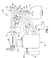
- an INO system 10 is shown in block diagram form.
- the system 10 includes a respiratory circuit 12 for delivering gases to a patient 14, a source 16 of gas containing NO, an NO monitoring and delivery subsystem 18, and a gas scavenger 20.
- a respiratory circuit 12 for delivering gases to a patient 14
- a source 16 of gas containing NO for delivering gases to a patient 14
- a source 16 of gas containing NO for delivering gases to a patient 14
- an NO monitoring and delivery subsystem 18 for delivering gases to a patient 14
- a gas scavenger 20 a gas scavenger 22.
- the respiratory circuit 12 includes an inspiratory limb 22 and an expiratory limb 24, each extending between conventional ventilator 26 and the patient 14.
- the illustrated inspiratory limb 22 is composed of inspiratory line 28 and patient tube 30.
- the expiratory limb 24 is composed of the patient tube 30 and expiratory line 32. It will thus be appreciated that the patient tube 30 accommodates bi-directional flow and forms a portion of both the inspiratory 22 and expiratory 24 limbs.
- the patient tube 30, inspiratory line 28 and expiratory line 32 are joined by a conventional we valve 34 that operates in synchronization with the patient's breathing to control flow through the inspiratory 22 and expiratory 24 limbs.
- the patient tube 30 terminates in a conventional mask or endotracheal breathing tube 36 for interfacing with the patient's respiratory system.
- the ventilator 26 is conventionally used to deliver respiratory and/or anesthetic gases to the patient 14, depending on the particular application.
- the ventilator 26 may receive inputs of air, O 2 , N 2 O and anesthetic agents (e.g., Isoflurane, Enflurane, Halothane, Desflurane and Sevoflurane), as generally indicated by arrows 38, from appropriate sources.
- anesthetic agents e.g., Isoflurane, Enflurane, Halothane, Desflurane and Sevoflurane
- respiratory gases pass from the ventilator 26 to a heated humidifier 40 that conditions the respiratory gases for inhalation by the patient 14.
- NO subsystem interfaces mounted on the inspiratory limb 22 of the illustrated embodiment. These are, in reverse flow sequence: a flow sensor 42, such as a Hamilton Medical Differential Pressure Flow Sensor, for bidirectional gas flow measurement at the patient 14; a sample gas port 44, located at or next to the wye valve 34, for diverting a portion of the flow from the patient tube 30 into a side stream 46 to NO subsystem 18 (a temperature sensor may also be included at this location to sense the temperature of gas inhaled and/or exhaled by the patient 14); a pressure sensor 48 for sensing the proximal patient airway pressure; a port 50 for injecting an NO containing gas (e.g., NO/N 2 ) into the inspiratory limb 22; a sensor unit 52 for distal airway pressure and temperature measurement of the heated, saturated respiratory gases delivered by the ventilator 26; and a flow measurement sensor 54, such as a Turbine Vane Transducer, for respiratory gas flow measurement.
- a flow sensor 42 such as a Hamilton Medical Differenti
- the expiratory limb 24 includes an expiratory valve 56 for ensuring one-way flow through the expiratory line 32 of gases expired by the patient 14.
- the expired gases may include carbon dioxide (CO 2 ), O 2 , N 2 , nitrogen trioxide (N 2 O 3 ) and anesthetic agents.
- the expiratory line 32 delivers the expired gases to the ventilator 26. From the ventilator 26 the expired gases may be scrubbed and scavenged prior to venting.
- the source 16 of NO-containing gas can be a gas pipeline, as provided in some operating rooms and intensive care units, or a gas canister(s) as shown.
- gas canisters of NO are delivered in a pressurized state and a typical pressure is on the order of about 2000 psi with a concentration of NO on the order of about 400-2000 ppm.
- the remainder of the gas in the canister may be N 2 or another preferably inert gas.
- Pressure regulators 58 are employed in the illustrated embodiment to reduce the pressure of the NO-containing gas to acceptable levels for operation of the system 10, e.g., to about 40 psi or lower.
- a solenoid shutoff valve (not shown) may also be employed in conjunction with the source 16 to provide ON/OFF capability independent of mechanical valving.
- a separate supply of preferably inert gas such as N 2 may be employed to reduce the concentration of NO as necessary.
- the NO subsystem 18 performs a number of functions including: monitoring respiration circuit parameters; receiving the side stream 46 and measuring concentrations of NO 2 , NO and O 2 ; determining the concentrations of NO 2 , NO and O 2 delivered to the patient 14 based on the measured concentrations; and controllably delivering NO-containing gas to the inspiratory limb 22 in amounts appropriate for achieving the desired therapeutic effects.
- the desired concentration of delivered NO for INO therapy typically ranges from about 5-80 ppm, although some studies have reported benefits at levels less than 1 ppm. NO 2 concentrations of less than 1 ppm may also be of interest.
- the illustrated system 10 preferably monitors NO 2 in the range of about 0-10 ppm, NO in the range of 0-200 ppm and O 2 in the range of 0-100%. Appropriate alarms may be provided in connection with selected parameter limits.
- the NO subsystem 18 receives parameter information from a variety of sensors associated with the respiratory circuit 12.
- the ventilator flow, pressure and temperature parameters apply primarily to the NO gas delivery function of the NO subsystem 18.
- these ventilator parameters directly affect the relationship between the amount of NO containing gas delivered to the inspiratory line 28 and the concentration of NO delivered to the patient 14.
- the patient flow, pressure, temperature and measured NO 2 , NO and O 2 concentrations apply primarily to the monitoring or feedback function of the NO subsystem 18.
- the measured concentrations will represent a weighted average gas concentration at the patient interface due to the longer response time of the electrochemical sensor cells in relation to the patient circuit flow dynamics.
- this relationship may be theoretically or empirically derived in order to increase system accuracy. In connection with the illustration system, this relationship has been empirically derived and may be continually or periodically updated based on experience with the system 10.
- controller 60 which may include a microprocessor based computing system.
- the controller 60 which controls operation of the NO subsystem 18 via a communications link such as an RS-232 interface, receives the respiratory circuit parameter information from the various sensors as described above.
- the controller 60 also receives inputs from a user interface such as a keypad, cursor device or touch screen (not shown) regarding patient treatment parameters such as desired NO delivery concentration. Based on this information, the controller 60 provides signals to control delivery of the NO containing gas.
- the NO subsystem 18 delivers NO containing gas from the source 16 to the inspiratory limb 22 via NO 2 scrubber 62 which removes NO 2 from the gas.
- Fig. 1 also shows a conventional scavenge system 20 that scavenges the side stream gas prior to release to the ambient environment.
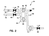
- Fig. 2 illustrates one embodiment of a side stream gas monitoring assembly 64 that can be implemented as part of the NO subsystem 18 of Fig. 1.
- the gas monitoring assembly 64 of Fig. 2 provides direct side stream measurement information regarding NO, NO 2 and O 2 concentrations proximate to the patient.
- the illustrated assembly 64 includes NO 2 and NO electrochemical cells 66 and 68, respectively, in parallel flow lines, and an O 2 electrochemical cell 70 disposed downstream from the NO and NO 2 cells 66 and 68.
- Sample gas is delivered into a manifold section 72 of the assembly 64 via side stream flow line 74 and sample gas valve 76.
- Air may also be delivered to the manifold section 72 via vent line 78 and vent valve 80.
- the valves 76 and 80 allow gas to flow to the sensors 66, 68 and 70. As previously noted, the sample gas is saturated.
- the vent line 78 and valve 80 allows air to mix with the saturated gas so as to reduce the relative humidity of the gas to within the operating range of the cells 66, 68 and 70.
- the vent valve 80 can also be opened to auto zero the cells 66, 68 and 70 and pressure sensor 82.
- a temperature sensor84 is mounted in side stream flow line 74 to allow for temperature related concentration adjustments, thereby improving accuracy.
- Electrochemical cells include an electrolyte solution designed to be reactive to the specific type of gas to be measured. The gas is exposed to the electrolyte solution through a diffusion barrier interface. The reaction of the gas with the electrolyte solution produces an electric current that is proportional to the amount of the specific gas to be measured in the gas sample. Although electrochemical cells are designed to be selective to the specific gas to be measured by the cell, NO cells consume NO 2 and vice versa. The parallel design reduces such sources of interference error.
- a temperature sensor 86, pressure sensor 82 and the O 2 cell 70 are positioned downstream from the parallel flow section. Temperature sensor 86 is employed in conjunction with sensor 84 to allow for temperature related adjustments to the concentration measurement. Pressure sensor 82 is used in conjunction with valves 76 and 80 to ensure that the cells 66-70 receive adequate flow for the desired measurements.
- the O 2 cell can be located downstream as shown due to the reduced O 2 cell sensitivity. Gas consumption by the NO and NO 2 cells 66 and 68 will not significantly affect the O 2 cell measurement. Moreover, arranging the O 2 cell in series with the parallel flow section eases flow past the NO and NO 2 cells 66 and 68. From the O 2 cell 70, the gas flows through scavenger valve 88 to a scavenger (not shown) prior to release to the ambient environment.
- Fig. 3 is a pneumatic flow diagram showing an alternative embodiment of a gas monitoring assembly 94 according to the present invention.
- the sample gas is drawn through the assembly 94 by a pump 96 such as a conventional vacuum pump.
- a pump 96 such as a conventional vacuum pump.
- hydrophobic filter 97 that removes liquid and other matter that may impair cell operation, across the diffusion barrier of an NO 2 electrochemical cell 98, across the diffusion barrier of an NO electrochemical cell 100 and around an O 2 electrochemical cell 102, all of which are located upstream from the pump 96.
- the illustrated O 2 cell 102 works on a partial pressure principle, and is enveloped by the gas, rather than being exposed only at a diffusion barrier.
- the gas passes to scavenger 104 prior to release to the ambient environment.
- Each of the cells 98, 100 or 102 is preferably enclosed in a sealed chamber so that the electrochemical reaction rates measured are due to the concentration of the gas to be measured, and is not due to pressure differences between the sample gas and the ambient environment. Because of this sealed environment and the positioning of the cells 98-102 upstream from the pump 96, the cells 98-102 will be maintained at a subambient pressure. Moreover, this cell positioning relative to the pump 96 facilitates isolation of the cells 98-102 from pressure fluctuations associated with pump operation. The illustrated sequence of the cells 98-102 with the NO 2 cell 98 located upstream from the NO cell 100 has been found to minimize measurement interference in the serial measurement environment.
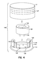
- Figs. 4 and 5 show exploded, perspective and side, partially cross-section views, respectively, of an electrochemical cell housing 106 for an NO or NO 2 cell 108 according to the present invention.
- the housing 108 which may be constructed of molded plastic, includes a base 110 and a cover 112 that can be engaged to enclose the cell 108.
- An O-ring 114 seated in a groove 116 on the base 110 seals against the cover 112, when the cover 112 and base 110 are engaged, to seal the interior chamber where the cell 108 is housed.
- the cover 112 is maintained in the engaged position by a molded key lock channels 118 of the base 110 which receive corresponding molded lock tabs 134 (Fig. 5) formed on an inside surface of the cover 112.
- the base 110 also includes molded gas passageways 120 for routing sample gas across the cell diffusion barrier 122, and molded sockets 124 for receiving the terminal pins 126 of cell 108. Additionally, the base 110 includes an open area 128 to facilitate finger access to the cell 108.
- the illustrated cover 112 includes a finger grip 127 to facilitate engagement and disengagement.
- Fig. 5 shows the mounting of the base 110 and cell 108 on a mount 130 including a printed circuit board (PCB) 132.
- the pins 126 extend through base sockets 124 when the cell 108 is plugged into the base 108 to electrically interface with the PCB 132.
- Pneumatic tubes 136 extend through the mount 130 and plug into the molded channels 118 of base 108 to deliver sample gas into and extract gas from the housing 106.
- the socket and pin pattern can be varied as between the NO 2 and NO cells to prevent misuse of the cells.
- the lock channel and tab configuration is arranged to ensure proper orientation of the cover 112 and alignment of any flow directing structure of the cover 112 with the gas passageways 120.
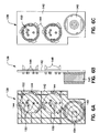
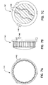
- Figs. 6A - 7C show an alternative embodiment of a housing for the cells. More particularly, Figs. 6A - 6C show top, side and bottom views, respectively, of a housing base 138 with mounted O 2 cell cover 140. Figs. 7A - 7C show top, side and bottom views, respectively, of a cover 141 for the NO 2 or NO cell.
- the illustrated base 138 which may be constructed of molded plastic, includes a base plate 142, molded lock channel structures 144 extending upwardly from the base plate 142 to engage lock tab structures 146 (Figs.
- Fig. 6A shows openings 154 on the upper surface of the O 2 cell cover 140 for delivering gas to and removing gas from the interior of the cover 140.
- Fig. 6C shows various structural elements for aligning and interfacing the base 138 with a PCB.
- Fig. 7C shows a rib structure 156 formed on the interior surface of the cover 141 for routing gas into a narrow channel between the openings 152 (Figs. 6A - 6C) over the electrochemical cell (not shown). Such routing promotes gas flow and reduces dead space, thereby improving cell response time.
- the invention as described in the various exemplary embodiments above, thus allows for continuous and accurate INO therapy monitoring using electrochemical cell technology. In addition, the invention provides good sensor response times with reduced cross-sensor interference.
Landscapes
- Health & Medical Sciences (AREA)
- Emergency Medicine (AREA)
- Pulmonology (AREA)
- Engineering & Computer Science (AREA)
- Anesthesiology (AREA)
- Biomedical Technology (AREA)
- Heart & Thoracic Surgery (AREA)
- Hematology (AREA)
- Life Sciences & Earth Sciences (AREA)
- Animal Behavior & Ethology (AREA)
- General Health & Medical Sciences (AREA)
- Public Health (AREA)
- Veterinary Medicine (AREA)
- Measurement Of The Respiration, Hearing Ability, Form, And Blood Characteristics Of Living Organisms (AREA)
Applications Claiming Priority (2)
| Application Number | Priority Date | Filing Date | Title |
|---|---|---|---|
| US84421897A | 1997-04-18 | 1997-04-18 | |
| US884218 | 1997-04-18 |
Publications (2)
| Publication Number | Publication Date |
|---|---|
| EP0872254A2 true EP0872254A2 (de) | 1998-10-21 |
| EP0872254A3 EP0872254A3 (de) | 1999-08-11 |
Family
ID=25292153
Family Applications (1)
| Application Number | Title | Priority Date | Filing Date |
|---|---|---|---|
| EP98302311A Withdrawn EP0872254A3 (de) | 1997-04-18 | 1998-03-26 | Überwachungssystem für Stickstoffmonoxid |
Country Status (2)
| Country | Link |
|---|---|
| EP (1) | EP0872254A3 (de) |
| CA (1) | CA2233392A1 (de) |
Cited By (8)
| Publication number | Priority date | Publication date | Assignee | Title |
|---|---|---|---|---|
| WO2001021239A1 (en) * | 1999-09-22 | 2001-03-29 | Instrumentarium Corporation | A method to improve oxygenation in subjects suffering impaierd oxygenation |
| WO2001041856A3 (en) * | 1999-12-08 | 2002-02-21 | Pulmonox Medical Corp | Multi-gas delivery system |
| WO2002038209A1 (en) * | 2000-11-07 | 2002-05-16 | Aneo Ab | Arrangement in ventilatory treatment of the lungs |
| US6694969B1 (en) | 1999-09-22 | 2004-02-24 | Instrumentarium Corp. | Method to improve oxygenation in subjects suffering impaired oxygenation |
| AU2003259001B2 (en) * | 2002-09-16 | 2008-05-22 | Aerocrine Ab | Apparatus and method for diagnostic gas analysis |
| EP2522384A1 (de) | 2011-05-10 | 2012-11-14 | Air Liquide Medical Systems | NO-Verteilungsgerät mit integierter Kalibrierlinie und entsprechende Anlage |
| EP2581103A1 (de) | 2011-10-12 | 2013-04-17 | Air Liquide Medical Systems | Verfahren zur Einstellung eines Geräts zur Gasverteilung, das von einer NO-Quelle gespeist wird |
| WO2015153713A1 (en) * | 2014-04-01 | 2015-10-08 | Ino Therapeutics Llc | Systems and method for delivery of therapeutic gas to patients in need thereof using enhanced breathing circuit gas (bcg) flow measurement |
Family Cites Families (6)
| Publication number | Priority date | Publication date | Assignee | Title |
|---|---|---|---|---|
| GB8824865D0 (en) * | 1988-10-24 | 1988-11-30 | Antec Systems | Gas sampling device & water trap |
| DE4325319C1 (de) * | 1993-07-29 | 1994-04-28 | Messer Griesheim Gmbh | Gerät zur kontrollierten Zudosierung von NO zur Atemluft von Patienten |
| SE9302478L (sv) * | 1993-07-22 | 1994-11-07 | Siemens Elema Ab | Gasblandning och apparat för att tillföra gasblandningen till lungorna hos ett levande väsen |
| DE4327730C1 (de) * | 1993-08-18 | 1995-03-02 | Messer Griesheim Gmbh | Einrichtung zum Verarbreichen von NO an spontanatmende Patienten mit pulmonalen Krankheitsbildern |
| US5558083A (en) * | 1993-11-22 | 1996-09-24 | Ohmeda Inc. | Nitric oxide delivery system |
| ATE228869T1 (de) * | 1996-02-27 | 2002-12-15 | Koster Henk W | Atmungs-system mit zusätzlicher verabreichung von gas |
-
1998
- 1998-03-25 CA CA002233392A patent/CA2233392A1/en not_active Abandoned
- 1998-03-26 EP EP98302311A patent/EP0872254A3/de not_active Withdrawn
Non-Patent Citations (1)
| Title |
|---|
| None |
Cited By (17)
| Publication number | Priority date | Publication date | Assignee | Title |
|---|---|---|---|---|
| WO2001021239A1 (en) * | 1999-09-22 | 2001-03-29 | Instrumentarium Corporation | A method to improve oxygenation in subjects suffering impaierd oxygenation |
| US6694969B1 (en) | 1999-09-22 | 2004-02-24 | Instrumentarium Corp. | Method to improve oxygenation in subjects suffering impaired oxygenation |
| WO2001041856A3 (en) * | 1999-12-08 | 2002-02-21 | Pulmonox Medical Corp | Multi-gas delivery system |
| WO2002038209A1 (en) * | 2000-11-07 | 2002-05-16 | Aneo Ab | Arrangement in ventilatory treatment of the lungs |
| AU2003259001B2 (en) * | 2002-09-16 | 2008-05-22 | Aerocrine Ab | Apparatus and method for diagnostic gas analysis |
| EP2522384A1 (de) | 2011-05-10 | 2012-11-14 | Air Liquide Medical Systems | NO-Verteilungsgerät mit integierter Kalibrierlinie und entsprechende Anlage |
| FR2975010A1 (fr) * | 2011-05-10 | 2012-11-16 | Air Liquide Medical Systems | Appareil de distribution de no avec ligne de calibration integree et installation associee |
| EP2581103A1 (de) | 2011-10-12 | 2013-04-17 | Air Liquide Medical Systems | Verfahren zur Einstellung eines Geräts zur Gasverteilung, das von einer NO-Quelle gespeist wird |
| WO2015153713A1 (en) * | 2014-04-01 | 2015-10-08 | Ino Therapeutics Llc | Systems and method for delivery of therapeutic gas to patients in need thereof using enhanced breathing circuit gas (bcg) flow measurement |
| JP2017509432A (ja) * | 2014-04-01 | 2017-04-06 | イノ セラピューティクス エルエルシー | 促進呼吸回路ガス(bcg)の流量測定を使用して治療ガスを必要な患者に供給するシステム及び方法 |
| EP3372267A1 (de) * | 2014-04-01 | 2018-09-12 | Ino Therapeutics LLC | Systeme zur verabreichung von therapeutischem gas an bedürftige patienten unter verwendung einer verbesserten atemgasdurchflussmessung |
| US10226592B2 (en) | 2014-04-01 | 2019-03-12 | Mallinckrodt Hospital Product Ip Limited | Systems and method for delivery of therapeutic gas to patients in need thereof using enhanced breathing circuit gas (BCG) flow measurement |
| US10232138B2 (en) | 2014-04-01 | 2019-03-19 | Mallinckrodt Hospital Product Ip Limited | Systems and method for delivery of therapeutic gas to patients in need thereof using enhanced breathing circuit gas (BCG) flow measurement |
| AU2019283897B2 (en) * | 2014-04-01 | 2020-10-01 | Mallinckrodt Hospital Products IP Limited | Systems and method for delivery of therapeutic gas to patients in need thereof using enhanced breathing circuit gas (BCG) flow measurement |
| US11260196B2 (en) | 2014-04-01 | 2022-03-01 | Mallinckrodt Pharmactuticals Ireland Limited | Systems and method for delivery of therapeutic gas to patients in need thereof using enhanced breathing circuit gas (BCG) flow measurement |
| US11471641B2 (en) | 2014-04-01 | 2022-10-18 | Mallinckrodt Pharmaceuticals Ireland Limited | Systems and method for delivery of therapeutic gas to patients in need thereof using enhanced breathing circuit gas (BCG) flow measurement |
| AU2022218487B2 (en) * | 2014-04-01 | 2024-02-29 | Mallinckrodt Pharmaceuticals Ireland Limited | Systems and method for delivery of therapeutic gas to patients in need thereof using enhanced breathing circuit gas (bcg) flow measurement |
Also Published As
| Publication number | Publication date |
|---|---|
| CA2233392A1 (en) | 1998-10-18 |
| EP0872254A3 (de) | 1999-08-11 |
Similar Documents
| Publication | Publication Date | Title |
|---|---|---|
| CA2133516C (en) | Nitric oxide delivery system | |
| US20090090359A1 (en) | Respiratory Anaesthesia Apparatus with Device for Measuring the Xenon Concentration | |
| EP0894506B1 (de) | On-line Erfassung und Korrektur in einem Narkosemittelverabreichungssystem | |
| EP0919253B1 (de) | Modulares Narkosebeatmungssystem | |
| US6213120B1 (en) | Device and method for determining gas volume and volumetric changes in a ventilator | |
| AU2008271709B2 (en) | A gas mixing device for an air-way management system | |
| AU4639196A (en) | A pneumatic system for a ventilator | |
| JPH07155378A (ja) | 呼吸ガス供給装置 | |
| US20070181126A1 (en) | Method and apparatus for ventilating a patient with a breathing gas mixture formed from nitric oxide, air, and oxygen | |
| EP0832662B1 (de) | Narkosesysteme | |
| US7703455B2 (en) | Apparatus and method for supplying respiratory gas to a patient in which respiratory gas components are metered with great accuracy | |
| SK44394A3 (en) | Device for controlled dosing "no" into air inhaled by patients | |
| US20230285710A1 (en) | Apparatus for supplying no to two gas outlets | |
| EP0872254A2 (de) | Überwachungssystem für Stickstoffmonoxid | |
| EP3479862A1 (de) | Verfahren für inhalationswirkung auf den körper und vorrichtung zur durchführung des verfahrens | |
| Troncy et al. | Inhaled nitric oxide: technical aspects of administration and monitoring | |
| JP7262832B2 (ja) | 定期的な圧力放出を伴う空気-酸素混合機 | |
| US8870784B2 (en) | Precision of xenon content measurement in a ventilatory anesthesia apparatus | |
| Verkaaik et al. | High flow closed circuit anaesthesia | |
| SU1678380A1 (ru) | Система управлени анестезией | |
| JP2001095921A (ja) | 麻酔方法及び麻酔システム | |
| US20240316298A1 (en) | Device for calibrating the sensors of an no delivery apparatus | |
| CN222917937U (zh) | 一种气路系统及呼吸机 | |
| US20260014342A1 (en) | No supply installation comprising an no delivery apparatus and an anaesthesia ventilator | |
| JP3103493B2 (ja) | No吸入用の3種ガス混合装置 |
Legal Events
| Date | Code | Title | Description |
|---|---|---|---|
| PUAI | Public reference made under article 153(3) epc to a published international application that has entered the european phase |
Free format text: ORIGINAL CODE: 0009012 |
|
| AK | Designated contracting states |
Kind code of ref document: A2 Designated state(s): AT BE CH DE DK ES FI FR GB GR IE IT LI LU MC NL PT SE |
|
| AX | Request for extension of the european patent |
Free format text: AL;LT;LV;MK;RO;SI |
|
| RIN1 | Information on inventor provided before grant (corrected) |
Inventor name: GONZALES, CHARLES Inventor name: GULL, KATHLEEN A. BERGERON C/O PALO ALTO DESIGN Inventor name: WOBERMIN, JIM |
|
| PUAL | Search report despatched |
Free format text: ORIGINAL CODE: 0009013 |
|
| AK | Designated contracting states |
Kind code of ref document: A3 Designated state(s): AT BE CH DE DK ES FI FR GB GR IE IT LI LU MC NL PT SE |
|
| AX | Request for extension of the european patent |
Free format text: AL;LT;LV;MK;RO;SI |
|
| RIC1 | Information provided on ipc code assigned before grant |
Free format text: 6A 61M 16/12 A, 6G 01N 33/00 B |
|
| RAP1 | Party data changed (applicant data changed or rights of an application transferred) |
Owner name: DATEX-OHMEDA, INC. |
|
| AKX | Designation fees paid | ||
| STAA | Information on the status of an ep patent application or granted ep patent |
Free format text: STATUS: THE APPLICATION IS DEEMED TO BE WITHDRAWN |
|
| 18D | Application deemed to be withdrawn |
Effective date: 20000212 |
|
| REG | Reference to a national code |
Ref country code: DE Ref legal event code: 8566 |