EP0873473B1 - Systeme d'injection de carburant - Google Patents
Systeme d'injection de carburant Download PDFInfo
- Publication number
- EP0873473B1 EP0873473B1 EP97932714A EP97932714A EP0873473B1 EP 0873473 B1 EP0873473 B1 EP 0873473B1 EP 97932714 A EP97932714 A EP 97932714A EP 97932714 A EP97932714 A EP 97932714A EP 0873473 B1 EP0873473 B1 EP 0873473B1
- Authority
- EP
- European Patent Office
- Prior art keywords
- pump
- pressure
- fuel
- fuel injection
- injection system
- Prior art date
- Legal status (The legal status is an assumption and is not a legal conclusion. Google has not performed a legal analysis and makes no representation as to the accuracy of the status listed.)
- Expired - Lifetime
Links
- 239000000446 fuel Substances 0.000 title claims description 75
- 238000002347 injection Methods 0.000 claims description 50
- 239000007924 injection Substances 0.000 claims description 50
- 238000002485 combustion reaction Methods 0.000 claims description 11
- 230000001360 synchronised effect Effects 0.000 description 4
- 230000008859 change Effects 0.000 description 3
- 239000000243 solution Substances 0.000 description 3
- 230000008901 benefit Effects 0.000 description 2
- 239000002828 fuel tank Substances 0.000 description 2
- 230000002269 spontaneous effect Effects 0.000 description 2
- 230000001133 acceleration Effects 0.000 description 1
- 230000009286 beneficial effect Effects 0.000 description 1
- 238000012508 change request Methods 0.000 description 1
- 238000006243 chemical reaction Methods 0.000 description 1
- 238000010586 diagram Methods 0.000 description 1
- 230000000694 effects Effects 0.000 description 1
- 230000006870 function Effects 0.000 description 1
- 238000003780 insertion Methods 0.000 description 1
- 230000037431 insertion Effects 0.000 description 1
- 238000000034 method Methods 0.000 description 1
- 230000004048 modification Effects 0.000 description 1
- 238000012986 modification Methods 0.000 description 1
- 230000008569 process Effects 0.000 description 1
- 230000001737 promoting effect Effects 0.000 description 1
Images

Classifications
-
- F—MECHANICAL ENGINEERING; LIGHTING; HEATING; WEAPONS; BLASTING
- F02—COMBUSTION ENGINES; HOT-GAS OR COMBUSTION-PRODUCT ENGINE PLANTS
- F02M—SUPPLYING COMBUSTION ENGINES IN GENERAL WITH COMBUSTIBLE MIXTURES OR CONSTITUENTS THEREOF
- F02M63/00—Other fuel-injection apparatus having pertinent characteristics not provided for in groups F02M39/00 - F02M57/00 or F02M67/00; Details, component parts, or accessories of fuel-injection apparatus, not provided for in, or of interest apart from, the apparatus of groups F02M39/00 - F02M61/00 or F02M67/00; Combination of fuel pump with other devices, e.g. lubricating oil pump
- F02M63/02—Fuel-injection apparatus having several injectors fed by a common pumping element, or having several pumping elements feeding a common injector; Fuel-injection apparatus having provisions for cutting-out pumps, pumping elements, or injectors; Fuel-injection apparatus having provisions for variably interconnecting pumping elements and injectors alternatively
- F02M63/0225—Fuel-injection apparatus having a common rail feeding several injectors ; Means for varying pressure in common rails; Pumps feeding common rails
-
- F—MECHANICAL ENGINEERING; LIGHTING; HEATING; WEAPONS; BLASTING
- F02—COMBUSTION ENGINES; HOT-GAS OR COMBUSTION-PRODUCT ENGINE PLANTS
- F02M—SUPPLYING COMBUSTION ENGINES IN GENERAL WITH COMBUSTIBLE MIXTURES OR CONSTITUENTS THEREOF
- F02M63/00—Other fuel-injection apparatus having pertinent characteristics not provided for in groups F02M39/00 - F02M57/00 or F02M67/00; Details, component parts, or accessories of fuel-injection apparatus, not provided for in, or of interest apart from, the apparatus of groups F02M39/00 - F02M61/00 or F02M67/00; Combination of fuel pump with other devices, e.g. lubricating oil pump
- F02M63/0003—Fuel-injection apparatus having a cyclically-operated valve for connecting a pressure source, e.g. constant pressure pump or accumulator, to an injection valve held closed mechanically, e.g. by springs, and automatically opened by fuel pressure
- F02M63/0007—Fuel-injection apparatus having a cyclically-operated valve for connecting a pressure source, e.g. constant pressure pump or accumulator, to an injection valve held closed mechanically, e.g. by springs, and automatically opened by fuel pressure using electrically actuated valves
-
- F—MECHANICAL ENGINEERING; LIGHTING; HEATING; WEAPONS; BLASTING
- F02—COMBUSTION ENGINES; HOT-GAS OR COMBUSTION-PRODUCT ENGINE PLANTS
- F02D—CONTROLLING COMBUSTION ENGINES
- F02D41/00—Electrical control of supply of combustible mixture or its constituents
- F02D41/30—Controlling fuel injection
- F02D41/38—Controlling fuel injection of the high pressure type
- F02D41/3809—Common rail control systems
Definitions
- the invention relates to a fuel injection system the genus of claim 1.
- a series injection pump is provided, the three pump pistons with corresponding pump work rooms.
- This pump piston delivers into the high-pressure fuel accumulator in a controlled quantity, the fuel injection quantity high-pressure delivery by one by one electrical control device controlled solenoid valve takes place in a discharge line of the respective Pump work room is arranged and with the closing the High pressure delivery phase determined.
- the each pump workspace through a piston-guided one Control edge connected to a fuel supply, so that the Pump workspace in bottom dead center with Fuel is filled.
- the pump pistons are thereby Multiple cams driven, so that they are synchronous to respective fuel injection point of each Fuel injection valves have their high-pressure delivery phase and thus approximately the same pressure in the high-pressure fuel reservoir can be adjusted. With help of a Pressure sensor, this pressure is detected and corresponding to a Setpoint from the electrical control device Control signal sent to the respective solenoid valves.
- This device has the disadvantage that it is very complex Control required for each pump element of the high pressure pump is.
- a pressure change in the high-pressure accumulator can only be carried out when one High pressure fuel injection takes place, so that a spontaneous Change in a higher pressure level in the high-pressure fuel reservoir can only be carried out with a delay.
- Around a pressure change in the memory can cause the pressure only increase during injection. That results in an undefined State of the memory pressure during the Injection so that it is difficult to get the right amount of injection as a sum effect of at a certain metering cross-section current pressure and time.
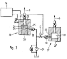
- a fuel injection system of the type according to the invention has a high-pressure pump 1, which is synchronous with the speed associated internal combustion engine is driven. This sucks 2 fuel from a fuel tank and promotes this via a high-pressure fuel line 3, preferably controlled by an electrically controlled control valve, here a solenoid valve 4, and one in the conveying direction opening check valve 5 in a high-pressure fuel accumulator 6.
- Fuel lines 8 lead from these Fuel injection valves 9 on the internal combustion engine 10. The from the fuel injection valves 9 to the internal combustion engine the amount of fuel delivered is in each case by a preferably electrically controlled valve, in In the present embodiment, a solenoid valve 11 is controlled.
- valves are controlled by a Electrical control unit 14, the signals from a pressure sensor 15 receives the pressure in the high-pressure fuel reservoir detected.
- the electrical control unit also receives signals of a speed sensor, an TDC sensor and other parameters of the internal combustion engine, such as the desired speed and operating conditions of the internal combustion engine and controls the fuel injection valves 9 accordingly With the help of the solenoid valves 11 according to quantity and time of injection of fuel.
- the electrical control unit also controls the solenoid valve 4, which is the delivery rate of the high pressure pump controls in the fuel storage and with this control the pressure in the fuel storage at the desired value holds.
- the high pressure pump shown only symbolically in FIG. 1 with solenoid valve 4 and check valve 5 is more detailed in Figure 2 shown.
- a first pump element 16 and a second pump element 17 Each of the Pump elements has a pump cylinder 19 in which a Pump piston 20, which is driven by a drive cam 22 is moved against the force of a spring 21.
- the pump pistons close each one in the cylinder 19 Working space 23, which via a fuel pressure line, in arranged in each case the pressure valve 5 opening in the conveying direction is connected to the high-pressure fuel reservoir 6 is.
- the pump work space is filled in each case via a filling bore 25, which is at the bottom dead center of the pump piston is opened by the end edge 26, so that Fuel from the reservoir 2 or if necessary via a pre-feed pump 24 into the pump work space 23 its full fulfillment can come.
- Delivery stroke is the filling bore 25 through the pump piston closed and the existing in the pump work room 23 Compressed fuel.
- This process then leads to High-pressure delivery in the high-pressure fuel reservoir 6, if that in a relief line 27 of the pump work space 23 arranged solenoid valve 4 is closed.
- This Solenoid valves 4 are, as already said above, by the electrical one Control unit 14 controlled so that it is in the high-pressure fuel reservoir 6 sets a desired pressure.
- the first pump element 16 controlled by the solenoid valve so that the Pump working space 23 over a certain pump piston delivery stroke is closed, so that high-pressure delivery via this stroke into the high pressure accumulator.
- a bore 28 in the from the end face 26 of the pump piston goes out and to a circumferential control groove 29 am Pump piston leads, it is possible to achieve a maximum delivery stroke of the pump piston by using the control groove this maximum delivery stroke the pump workspace with the Filling hole 25 and thus connects to the low pressure chamber.
- the Maximum pressure is then preferably promoted by a Closing of the solenoid valve from a certain pump piston stroke initiated and thus controlled the high pressure output.
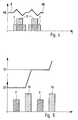
- the pressure first increases, which then drops as the injection occurs and after the end of injection by the rest of the High-pressure delivery of the high-pressure fuel pump again the original level can be raised.
- the high-pressure fuel delivery quantities F the injection quantities adjusted, so there is an overall average pressure level MD a.
- the second pump element 17 driven, but it is because of the open Solenoid valve 4 no high-pressure delivery in the high-pressure fuel reservoir.
- the fuel moved by the pump piston 20 is in the fuel tank via the open solenoid valve 2 promoted.
- the pressure curve shows that with insertion promoting FK the pressure level from a first level D1 is raised to a second level D2. About the Injection remains at this level due to the promotion of the get first pump element.
- the one in FIG. 5 reproduced curve with pressure decrease at Quantity withdrawal during the injection in FIG. 4 been neglected.
- a modification of the control of the second pump element according to embodiment Figure 2 can with the second pump element 17 'of Figure 3, the control valve as a control valve 4 ', here again as a solenoid valve instead of in a separate discharge line now also in the inlet of the pre-feed pump 24 to the pump work chamber 23 or Filling bore 25 may be arranged.
- the previously provided relief line can be omitted.
- Control valve 4 ' opens so that a complete filling of the Pump work room 23 is possible.
- the control valve 4 ' is closed.
- a constant stroke of the pump element also serves here 17 'of the high pressure delivery when it is switched on.
- the bore 28 with the filling bore 25 via the control groove 29 can also have a check valve 30 producible connection to the pump work room 23 in the Suction phase are provided.
- a check valve 30 producible connection to the pump work room 23 in the Suction phase are provided.
Landscapes
- Engineering & Computer Science (AREA)
- Chemical & Material Sciences (AREA)
- Combustion & Propulsion (AREA)
- Mechanical Engineering (AREA)
- General Engineering & Computer Science (AREA)
- Fuel-Injection Apparatus (AREA)
Claims (7)
- Système d'injection de carburant comprenant une pompe à haute pression (1) qui fournit le carburant du réservoir (2) à un accumulateur haute pression (6) d'où le carburant alimente par des conduites de carburant (8), différents injecteurs (9), commandés par un appareil de commande électrique (14) pour le doser et l'injecter de manière commandée dans le temps, dans le moteur à combustion interne,caractérisé en ce quela pompe à haute pression ayant un ou plusieurs éléments de pompe (16, 17) avec des pistons de pompe (20) entraínés par des cames d'entraínement (22) elles-mêmes entraínées en synchronisme avec la vitesse de rotation du moteur à combustion interne, et chaque piston délimite une chambre de travail de pompe (23) dans un cylindre de pompe (19), et lors de la course d'aspiration du piston de pompe, la chambre reçoit du carburant et lors de la course de refoulement du piston (20), la chambre fournit le carburant à travers une vanne de commande (4) notamment une vanne à commande électrique, suivant une quantité commandée, à l'accumulateur à haute pression (6), etau moins un premier (16) élément de pompe est commandé par les cames d'entraínement (22) et la vanne de commande (4) pour que le débit à haute pression se fasse en synchronisme avec l'injection de carburant par les injecteurs (9),
un second élément de pompe (17, 17') est commandé par la came d'entraínement (22) et une vanne de commande (4, 4') pour être libéré ou coupé avec un débit à haute pression, constant, et selon les paramètres de fonctionnement notamment la pression régnant dans l'accumulateur à haute pression (6). - Système d'injection de carburant selon la revendication 1,
caractérisé en ce que
le second des éléments de pompe (17, 17') débite dans un intervalle de temps compris entre les opérations d'injection de carburant, des différents injecteurs de carburant (9). - Système d'injection selon l'une quelconque des revendications 1 ou 2,
caractérisé en ce que
chacune des chambres de travail de pompe (23) des premiers éléments de pompe (16), lors de la course d'aspiration du piston de pompe (20) est totalement remplie de carburant et le débit du piston de pompe (20) est défini par l'intervalle de temps de fermeture de la vanne commandée (4) équipant la conduite de décharge (27) de chaque chambre de travail de pompe (20). - Système d'injection selon l'une quelconque des revendications 1 ou 2,
caractérisé en ce que
le débit du second des éléments de pompe (17, 17'), fonctionnant à un débit à haute pression, constant, est coupé ou libéré par la vanne commandée (4, 4'). - Système d'injection selon la revendication 4,
caractérisé en ce que
la vanne de commande (4') commande un perçage de remplissage (25) de la chambre de travail (23) du second élément de pompe (17'). - Système d'injection selon la revendication 4,
caractérisé en ce que
la vanne de commande (4) commande une conduite de décharge (27) de la chambre de travail (23) du second élément de pompe (17). - Système d'injection selon l'une quelconque des revendications 1 à 4,
caractérisé en ce que
la came d'entraínement (22) est une came multiple notamment une came triple.
Applications Claiming Priority (3)
| Application Number | Priority Date | Filing Date | Title |
|---|---|---|---|
| DE19646581 | 1996-11-12 | ||
| DE19646581A DE19646581A1 (de) | 1996-11-12 | 1996-11-12 | Kraftstoffeinspritzsystem |
| PCT/DE1997/001370 WO1998021470A1 (fr) | 1996-11-12 | 1997-06-30 | Systeme d'injection de carburant |
Publications (2)
| Publication Number | Publication Date |
|---|---|
| EP0873473A1 EP0873473A1 (fr) | 1998-10-28 |
| EP0873473B1 true EP0873473B1 (fr) | 2002-03-20 |
Family
ID=7811337
Family Applications (1)
| Application Number | Title | Priority Date | Filing Date |
|---|---|---|---|
| EP97932714A Expired - Lifetime EP0873473B1 (fr) | 1996-11-12 | 1997-06-30 | Systeme d'injection de carburant |
Country Status (9)
| Country | Link |
|---|---|
| US (1) | US6095118A (fr) |
| EP (1) | EP0873473B1 (fr) |
| JP (1) | JP3889057B2 (fr) |
| KR (1) | KR100482907B1 (fr) |
| CN (1) | CN1076789C (fr) |
| DE (2) | DE19646581A1 (fr) |
| ES (1) | ES2174267T3 (fr) |
| RU (1) | RU2177077C2 (fr) |
| WO (1) | WO1998021470A1 (fr) |
Families Citing this family (46)
| Publication number | Priority date | Publication date | Assignee | Title |
|---|---|---|---|---|
| BR0008300B1 (pt) * | 1999-02-17 | 2011-08-23 | sistema de injeção de combustìvel a gasolina para um motor de combustão interna, e, métodos para controlar a operação de um sistema de injeção de gasolina direta de alimentador comum de alta pressão para um motor de combustão interna, e para controlar um sistema de injeção de combustìvel a gasolina de alimentador comum. | |
| DE19948464A1 (de) * | 1999-10-08 | 2001-04-12 | Bosch Gmbh Robert | Common-Rail-Kraftstoffeinspritzsystem |
| US6866025B1 (en) * | 1999-11-18 | 2005-03-15 | Siemens Vdo Automotive Corp. | High pressure fuel pump delivery control by piston deactivation |
| EP1101931B1 (fr) * | 1999-11-19 | 2006-08-30 | CRT Common Rail Technologies AG | Système d'injection à haute pression avec common rail |
| JP2001207927A (ja) * | 2000-01-26 | 2001-08-03 | Mitsubishi Electric Corp | 燃料供給装置 |
| JP2001263198A (ja) * | 2000-03-14 | 2001-09-26 | Bosch Automotive Systems Corp | 燃料ポンプ及びこれを用いた燃料供給装置 |
| DE10023033A1 (de) * | 2000-05-11 | 2001-11-22 | Bosch Gmbh Robert | Verfahren zum Betreiben eines Kraftstoffzumesssystems einer direkteinspritzenden Brennkraftmaschine |
| DE10052629A1 (de) * | 2000-10-24 | 2002-05-08 | Bosch Gmbh Robert | Kraftstoffhochdruckpumpe mit veränderlicher Fördermenge |
| DE10057683B4 (de) * | 2000-11-21 | 2005-10-06 | Robert Bosch Gmbh | Kraftstoffeinspritzeinrichtung |
| JP4123729B2 (ja) * | 2001-03-15 | 2008-07-23 | 株式会社日立製作所 | 燃料供給装置の制御方法 |
| US6899083B2 (en) * | 2001-09-10 | 2005-05-31 | Stanadyne Corporation | Hybrid demand control for hydraulic pump |
| DE10153189A1 (de) * | 2001-10-27 | 2003-05-15 | Bosch Gmbh Robert | Kraftstoffpumpe, Kraftstoffsystem, Verfahren zum Betreiben eines Kraftstoffsystems sowie Brennkraftmaschine |
| KR20030048172A (ko) * | 2001-12-11 | 2003-06-19 | 현대자동차주식회사 | 캠을 이용한 실린더 디액티베이션 장치 |
| GB2383295A (en) * | 2001-12-19 | 2003-06-25 | Michael Ghahari | Repairable solid surface laminate |
| DE10215021A1 (de) * | 2002-04-05 | 2003-10-23 | Bosch Gmbh Robert | Kraftstoffeinspritzeinrichtung für eine Brennkraftmaschine |
| US7201147B2 (en) * | 2002-08-13 | 2007-04-10 | International Engine Intellectual Property Company, Llc | Control strategies for a variable displacement oil pump |
| JP4123952B2 (ja) * | 2003-02-06 | 2008-07-23 | トヨタ自動車株式会社 | 内燃機関の燃料供給システム |
| DE10315318A1 (de) * | 2003-04-04 | 2004-10-14 | Robert Bosch Gmbh | Verfahren zum Betreiben einer Brennkraftmaschine |
| US6973921B2 (en) * | 2003-12-12 | 2005-12-13 | Caterpillar Inc. | Fuel pumping system and method |
| JP4148145B2 (ja) * | 2004-01-22 | 2008-09-10 | 株式会社デンソー | 内燃機関の燃料供給装置 |
| ITBO20040322A1 (it) * | 2004-05-20 | 2004-08-20 | Magneti Marelli Powertrain Spa | Metodo ed impianto per l'iniezione diretta di carburante in un motore a combustione interna |
| ITBO20040323A1 (it) * | 2004-05-20 | 2004-08-20 | Magneti Marelli Powertrain Spa | Metodo di iniezione diretta di carburante in un motore a combustione interna |
| EP1612394B1 (fr) * | 2004-06-30 | 2011-04-27 | C.R.F. Società Consortile per Azioni | System d'injection pour moteur à combustion interne avec rampe commune |
| EP1783355A4 (fr) * | 2004-07-12 | 2010-08-25 | Yanmar Co Ltd | Dispositif d'injection de carburant d'accumulateur et moteur à combustion interne pourvu dudit dispositif d'injection de carburant d'accumulateur |
| JP2006046169A (ja) * | 2004-08-04 | 2006-02-16 | Toyota Motor Corp | 内燃機関の燃料圧力制御装置 |
| JP4552694B2 (ja) | 2005-03-02 | 2010-09-29 | トヨタ自動車株式会社 | 車両の燃料供給装置 |
| CA2602060C (fr) * | 2005-03-18 | 2011-05-17 | Toyota Jidosha Kabushiki Kaisha | Moteur a combustion interne a double systeme d'injection de carburant |
| US7398763B2 (en) | 2005-11-09 | 2008-07-15 | Caterpillar Inc. | Multi-source fuel system for variable pressure injection |
| JP4506700B2 (ja) * | 2006-03-27 | 2010-07-21 | 株式会社デンソー | 燃料噴射制御装置 |
| US7431017B2 (en) * | 2006-05-24 | 2008-10-07 | Caterpillar Inc. | Multi-source fuel system having closed loop pressure control |
| US7392791B2 (en) | 2006-05-31 | 2008-07-01 | Caterpillar Inc. | Multi-source fuel system for variable pressure injection |
| US7353800B2 (en) * | 2006-05-24 | 2008-04-08 | Caterpillar Inc. | Multi-source fuel system having grouped injector pressure control |
| US8015964B2 (en) * | 2006-10-26 | 2011-09-13 | David Norman Eddy | Selective displacement control of multi-plunger fuel pump |
| GB0622564D0 (en) * | 2006-11-13 | 2006-12-20 | Airbus Uk Ltd | Water scavenging system |
| US20080115770A1 (en) * | 2006-11-16 | 2008-05-22 | Merchant Jack A | Pump with torque reversal avoidance feature and engine system using same |
| FR2914959B1 (fr) * | 2007-04-13 | 2013-03-08 | Siemens Automotive Hydraulics Sa | Perfectionnement aux dispositifs d'alimentation de carburant sous haute pression par pompe transfert |
| DE102007034317A1 (de) * | 2007-07-24 | 2009-01-29 | Robert Bosch Gmbh | Brennkraftmaschine mit mehreren Zylindern |
| EP2063093A1 (fr) * | 2007-11-26 | 2009-05-27 | Delphi Technologies, Inc. | Système d'injection de carburant |
| EP2085603A1 (fr) * | 2008-01-31 | 2009-08-05 | Caterpillar Motoren GmbH & Co. KG | Système et procédé pour éviter la surchauffe de pompe CR |
| DE102008001019A1 (de) * | 2008-04-07 | 2009-10-08 | Robert Bosch Gmbh | Hochdruckpumpenanordnung mit einstempliger Hochdruckpumpe |
| DE102008041384A1 (de) * | 2008-08-20 | 2010-02-25 | Robert Bosch Gmbh | Vorrichtung zur Versorgung einer Verbrennungskraftmaschine mit Treibstoff |
| US8834134B2 (en) | 2010-12-20 | 2014-09-16 | Woodward, Inc. | Flow sensing dual pump switching system and method |
| JP5799919B2 (ja) | 2012-09-06 | 2015-10-28 | 株式会社デンソー | ポンプ制御装置 |
| US9422898B2 (en) * | 2013-02-12 | 2016-08-23 | Ford Global Technologies, Llc | Direct injection fuel pump |
| US10260444B2 (en) * | 2013-12-19 | 2019-04-16 | Fca Us Llc | Direct injection fuel system with controlled accumulator energy storage |
| DE102015209377B4 (de) * | 2015-05-21 | 2017-05-11 | Mtu Friedrichshafen Gmbh | Einspritzsystem für eine Brennkraftmaschine sowie Brennkraftmaschine mit einem solchen Einspritzsystem |
Family Cites Families (12)
| Publication number | Priority date | Publication date | Assignee | Title |
|---|---|---|---|---|
| SU1260552A2 (ru) * | 1981-06-01 | 1986-09-30 | Ордена Дружбы Народов Университет Дружбы Народов Им.Патриса Лумумбы | Система подачи топлива в дизель |
| SU1343080A1 (ru) * | 1986-01-14 | 1987-10-07 | Московский автомобильный завод им.И.А.Лихачева | Система подачи топлива дизельного двигател |
| SU1348552A1 (ru) * | 1986-04-04 | 1987-10-30 | Университет дружбы народов им.Патриса Лумумбы | Способ регулировани подачи топлива в цилиндры многоцилиндрового дизел |
| JPH07122422B2 (ja) * | 1986-05-02 | 1995-12-25 | 日本電装株式会社 | 燃料噴射装置 |
| IT210456Z2 (it) * | 1987-01-12 | 1988-12-30 | Iveco Fiat | Sistema di iniezione del combustibile ad accumulazione di pressione |
| US5197438A (en) * | 1987-09-16 | 1993-03-30 | Nippondenso Co., Ltd. | Variable discharge high pressure pump |
| US5058553A (en) * | 1988-11-24 | 1991-10-22 | Nippondenso Co., Ltd. | Variable-discharge high pressure pump |
| IT1238509B (it) * | 1989-11-07 | 1993-08-18 | Weber Srl | Collettore di carburante ad elevata pressione atto ad essere inserito tra una pompa di alimentazione del carburante ed almeno una valvola di iniezione del carburante azionata elettromagneticamente |
| JP3033214B2 (ja) * | 1991-02-27 | 2000-04-17 | 株式会社デンソー | 複数の燃料圧送手段による蓄圧式燃料供給方法及び装置と、複数の流体圧送手段を有する機器における異常判断装置 |
| JP2861429B2 (ja) * | 1991-02-27 | 1999-02-24 | 株式会社デンソー | ディーゼル機関の蓄圧式燃料噴射装置 |
| DE69200427T2 (de) * | 1991-04-04 | 1995-02-16 | Toyota Motor Co Ltd | Kraftstoffeinspritzvorrichtung einer Brennkraftmaschine. |
| RU2057965C1 (ru) * | 1993-06-01 | 1996-04-10 | Георгий Михайлович Легошин | Система топливоподачи силовой установки |
-
1996
- 1996-11-12 DE DE19646581A patent/DE19646581A1/de not_active Withdrawn
-
1997
- 1997-06-30 KR KR10-1998-0705097A patent/KR100482907B1/ko not_active Expired - Fee Related
- 1997-06-30 JP JP52200398A patent/JP3889057B2/ja not_active Expired - Fee Related
- 1997-06-30 DE DE59706681T patent/DE59706681D1/de not_active Expired - Lifetime
- 1997-06-30 CN CN97191632A patent/CN1076789C/zh not_active Expired - Fee Related
- 1997-06-30 WO PCT/DE1997/001370 patent/WO1998021470A1/fr not_active Ceased
- 1997-06-30 US US09/101,620 patent/US6095118A/en not_active Expired - Lifetime
- 1997-06-30 EP EP97932714A patent/EP0873473B1/fr not_active Expired - Lifetime
- 1997-06-30 ES ES97932714T patent/ES2174267T3/es not_active Expired - Lifetime
- 1997-06-30 RU RU98114976/06A patent/RU2177077C2/ru not_active IP Right Cessation
Also Published As
| Publication number | Publication date |
|---|---|
| RU2177077C2 (ru) | 2001-12-20 |
| US6095118A (en) | 2000-08-01 |
| DE19646581A1 (de) | 1998-05-14 |
| KR19990076969A (ko) | 1999-10-25 |
| ES2174267T3 (es) | 2002-11-01 |
| JP3889057B2 (ja) | 2007-03-07 |
| EP0873473A1 (fr) | 1998-10-28 |
| KR100482907B1 (ko) | 2005-07-21 |
| CN1076789C (zh) | 2001-12-26 |
| DE59706681D1 (de) | 2002-04-25 |
| WO1998021470A1 (fr) | 1998-05-22 |
| JP2000505177A (ja) | 2000-04-25 |
| CN1207160A (zh) | 1999-02-03 |
Similar Documents
| Publication | Publication Date | Title |
|---|---|---|
| EP0873473B1 (fr) | Systeme d'injection de carburant | |
| EP0946830B1 (fr) | Systeme d'injection de carburant pour moteur a combustion interne | |
| DE3112381C2 (fr) | ||
| EP0116168B1 (fr) | Pompe d'injection de combustible | |
| DE19708152C2 (de) | Kraftstoffeinspritzsystem | |
| DE3436768C2 (fr) | ||
| DE3126393C2 (fr) | ||
| DE4313852A1 (de) | Kraftstoffeinspritzeinrichtung für Brennkraftmaschinen | |
| DE3217887A1 (de) | Kraftstoff-einspritzsystem fuer brennkraftmaschinen | |
| EP1282771A1 (fr) | Procede de fonctionnement d'un systeme de dosage de carburant d'un moteur a combustion interne a injection directe | |
| DE19625698B4 (de) | Einspritzeinrichtung zum kombinierten Einspritzen von Kraftstoff und Zusatzflüssigkeit | |
| DE10139054C1 (de) | Verfahren, Computerprogramm, Steuer- und/oder Regelgerät sowie Kraftstoffsystem für eine Brennkraftmaschine, insbesondere mit Direkteinspritzung | |
| EP0596054B1 (fr) | Dispositif d'injection de carburant pour moteurs a combustion interne | |
| EP1141539A1 (fr) | Pompe a piston pour carburant sous haute pression | |
| DE3382635T2 (de) | Verfahren und geraet fuer die genaue steuerung der kraftstoffeinspritzung in einer brennkraftmaschine. | |
| EP0946828B1 (fr) | Systeme d'injection de carburant d'un moteur a combustion interne | |
| DE3318236C2 (fr) | ||
| DE3444234A1 (de) | Kraftstoffeinspritzpumpe | |
| DE10200987A1 (de) | Verfahren, Computerprogramm und Steuer- und/oder Regelgerät zum Betreiben einer Brennkraftmaschine, sowie Brennkraftmaschine | |
| DE3521428A1 (de) | Kraftstoffeinspritzvorrichtung fuer brennkraftmaschinen | |
| EP0406592B1 (fr) | Pompe à injection de combustible | |
| DE4304967A1 (de) | Kraftstoffeinspritzeinrichtung für Brennkraftmaschinen | |
| DE19746490A1 (de) | Kraftstoffeinspritzanlage für eine Brennkraftmaschine | |
| DE10315318A1 (de) | Verfahren zum Betreiben einer Brennkraftmaschine | |
| DE102015205586B3 (de) | Hochdruckeinspritzvorrichtung für einen Verbrennungsmotor |
Legal Events
| Date | Code | Title | Description |
|---|---|---|---|
| PUAI | Public reference made under article 153(3) epc to a published international application that has entered the european phase |
Free format text: ORIGINAL CODE: 0009012 |
|
| AK | Designated contracting states |
Kind code of ref document: A1 Designated state(s): DE ES FR GB IT |
|
| 17P | Request for examination filed |
Effective date: 19981123 |
|
| GRAG | Despatch of communication of intention to grant |
Free format text: ORIGINAL CODE: EPIDOS AGRA |
|
| 17Q | First examination report despatched |
Effective date: 20010411 |
|
| GRAG | Despatch of communication of intention to grant |
Free format text: ORIGINAL CODE: EPIDOS AGRA |
|
| GRAH | Despatch of communication of intention to grant a patent |
Free format text: ORIGINAL CODE: EPIDOS IGRA |
|
| REG | Reference to a national code |
Ref country code: GB Ref legal event code: IF02 |
|
| GRAH | Despatch of communication of intention to grant a patent |
Free format text: ORIGINAL CODE: EPIDOS IGRA |
|
| GRAA | (expected) grant |
Free format text: ORIGINAL CODE: 0009210 |
|
| AK | Designated contracting states |
Kind code of ref document: B1 Designated state(s): DE ES FR GB IT |
|
| REF | Corresponds to: |
Ref document number: 59706681 Country of ref document: DE Date of ref document: 20020425 |
|
| GBT | Gb: translation of ep patent filed (gb section 77(6)(a)/1977) |
Effective date: 20020524 |
|
| ET | Fr: translation filed | ||
| REG | Reference to a national code |
Ref country code: ES Ref legal event code: FG2A Ref document number: 2174267 Country of ref document: ES Kind code of ref document: T3 |
|
| PLBE | No opposition filed within time limit |
Free format text: ORIGINAL CODE: 0009261 |
|
| STAA | Information on the status of an ep patent application or granted ep patent |
Free format text: STATUS: NO OPPOSITION FILED WITHIN TIME LIMIT |
|
| 26N | No opposition filed |
Effective date: 20021223 |
|
| PGFP | Annual fee paid to national office [announced via postgrant information from national office to epo] |
Ref country code: FR Payment date: 20120705 Year of fee payment: 16 Ref country code: GB Payment date: 20120621 Year of fee payment: 16 |
|
| PGFP | Annual fee paid to national office [announced via postgrant information from national office to epo] |
Ref country code: ES Payment date: 20120628 Year of fee payment: 16 |
|
| PG25 | Lapsed in a contracting state [announced via postgrant information from national office to epo] |
Ref country code: IT Free format text: LAPSE BECAUSE OF NON-PAYMENT OF DUE FEES Effective date: 20120630 |
|
| PGFP | Annual fee paid to national office [announced via postgrant information from national office to epo] |
Ref country code: DE Payment date: 20130828 Year of fee payment: 17 |
|
| PGFP | Annual fee paid to national office [announced via postgrant information from national office to epo] |
Ref country code: IT Payment date: 20120623 Year of fee payment: 16 |
|
| PGRI | Patent reinstated in contracting state [announced from national office to epo] |
Ref country code: IT Effective date: 20131025 |
|
| GBPC | Gb: european patent ceased through non-payment of renewal fee |
Effective date: 20130630 |
|
| REG | Reference to a national code |
Ref country code: FR Ref legal event code: ST Effective date: 20140228 |
|
| PG25 | Lapsed in a contracting state [announced via postgrant information from national office to epo] |
Ref country code: GB Free format text: LAPSE BECAUSE OF NON-PAYMENT OF DUE FEES Effective date: 20130630 |
|
| PG25 | Lapsed in a contracting state [announced via postgrant information from national office to epo] |
Ref country code: FR Free format text: LAPSE BECAUSE OF NON-PAYMENT OF DUE FEES Effective date: 20130701 |
|
| PGRI | Patent reinstated in contracting state [announced from national office to epo] |
Ref country code: IT Effective date: 20131025 |
|
| REG | Reference to a national code |
Ref country code: ES Ref legal event code: FD2A Effective date: 20140707 |
|
| PG25 | Lapsed in a contracting state [announced via postgrant information from national office to epo] |
Ref country code: ES Free format text: LAPSE BECAUSE OF NON-PAYMENT OF DUE FEES Effective date: 20130701 |
|
| REG | Reference to a national code |
Ref country code: DE Ref legal event code: R119 Ref document number: 59706681 Country of ref document: DE |
|
| REG | Reference to a national code |
Ref country code: DE Ref legal event code: R119 Ref document number: 59706681 Country of ref document: DE Effective date: 20150101 |
|
| PG25 | Lapsed in a contracting state [announced via postgrant information from national office to epo] |
Ref country code: DE Free format text: LAPSE BECAUSE OF NON-PAYMENT OF DUE FEES Effective date: 20150101 |