EP1101931B1 - Système d'injection à haute pression avec common rail - Google Patents
Système d'injection à haute pression avec common rail Download PDFInfo
- Publication number
- EP1101931B1 EP1101931B1 EP00122678A EP00122678A EP1101931B1 EP 1101931 B1 EP1101931 B1 EP 1101931B1 EP 00122678 A EP00122678 A EP 00122678A EP 00122678 A EP00122678 A EP 00122678A EP 1101931 B1 EP1101931 B1 EP 1101931B1
- Authority
- EP
- European Patent Office
- Prior art keywords
- high pressure
- duct
- injection system
- plunger cylinder
- pipe element
- Prior art date
- Legal status (The legal status is an assumption and is not a legal conclusion. Google has not performed a legal analysis and makes no representation as to the accuracy of the status listed.)
- Expired - Lifetime
Links
- 238000002347 injection Methods 0.000 title claims description 31
- 239000007924 injection Substances 0.000 title claims description 31
- 238000007789 sealing Methods 0.000 claims description 17
- 238000002485 combustion reaction Methods 0.000 claims description 5
- 239000000446 fuel Substances 0.000 claims description 3
- 239000012526 feed medium Substances 0.000 claims 3
- 230000001747 exhibiting effect Effects 0.000 claims 1
- 230000001105 regulatory effect Effects 0.000 claims 1
- 239000012530 fluid Substances 0.000 description 5
- 150000001875 compounds Chemical class 0.000 description 1
- 230000007423 decrease Effects 0.000 description 1
- 238000006073 displacement reaction Methods 0.000 description 1
- 238000009434 installation Methods 0.000 description 1
- 239000007788 liquid Substances 0.000 description 1
- 238000012423 maintenance Methods 0.000 description 1
- 238000004519 manufacturing process Methods 0.000 description 1
- 238000000465 moulding Methods 0.000 description 1
- 238000007493 shaping process Methods 0.000 description 1
- 239000000243 solution Substances 0.000 description 1
Images



Classifications
-
- F—MECHANICAL ENGINEERING; LIGHTING; HEATING; WEAPONS; BLASTING
- F02—COMBUSTION ENGINES; HOT-GAS OR COMBUSTION-PRODUCT ENGINE PLANTS
- F02M—SUPPLYING COMBUSTION ENGINES IN GENERAL WITH COMBUSTIBLE MIXTURES OR CONSTITUENTS THEREOF
- F02M63/00—Other fuel-injection apparatus having pertinent characteristics not provided for in groups F02M39/00 - F02M57/00 or F02M67/00; Details, component parts, or accessories of fuel-injection apparatus, not provided for in, or of interest apart from, the apparatus of groups F02M39/00 - F02M61/00 or F02M67/00; Combination of fuel pump with other devices, e.g. lubricating oil pump
- F02M63/02—Fuel-injection apparatus having several injectors fed by a common pumping element, or having several pumping elements feeding a common injector; Fuel-injection apparatus having provisions for cutting-out pumps, pumping elements, or injectors; Fuel-injection apparatus having provisions for variably interconnecting pumping elements and injectors alternatively
- F02M63/0225—Fuel-injection apparatus having a common rail feeding several injectors ; Means for varying pressure in common rails; Pumps feeding common rails
-
- F—MECHANICAL ENGINEERING; LIGHTING; HEATING; WEAPONS; BLASTING
- F02—COMBUSTION ENGINES; HOT-GAS OR COMBUSTION-PRODUCT ENGINE PLANTS
- F02M—SUPPLYING COMBUSTION ENGINES IN GENERAL WITH COMBUSTIBLE MIXTURES OR CONSTITUENTS THEREOF
- F02M39/00—Arrangements of fuel-injection apparatus with respect to engines; Pump drives adapted to such arrangements
- F02M39/02—Arrangements of fuel-injection apparatus to facilitate the driving of pumps; Arrangements of fuel-injection pumps; Pump drives
-
- F—MECHANICAL ENGINEERING; LIGHTING; HEATING; WEAPONS; BLASTING
- F02—COMBUSTION ENGINES; HOT-GAS OR COMBUSTION-PRODUCT ENGINE PLANTS
- F02M—SUPPLYING COMBUSTION ENGINES IN GENERAL WITH COMBUSTIBLE MIXTURES OR CONSTITUENTS THEREOF
- F02M55/00—Fuel-injection apparatus characterised by their fuel conduits or their venting means; Arrangements of conduits between fuel tank and pump F02M37/00
- F02M55/02—Conduits between injection pumps and injectors, e.g. conduits between pump and common-rail or conduits between common-rail and injectors
- F02M55/025—Common rails
-
- F—MECHANICAL ENGINEERING; LIGHTING; HEATING; WEAPONS; BLASTING
- F02—COMBUSTION ENGINES; HOT-GAS OR COMBUSTION-PRODUCT ENGINE PLANTS
- F02M—SUPPLYING COMBUSTION ENGINES IN GENERAL WITH COMBUSTIBLE MIXTURES OR CONSTITUENTS THEREOF
- F02M59/00—Pumps specially adapted for fuel-injection and not provided for in groups F02M39/00 -F02M57/00, e.g. rotary cylinder-block type of pumps
- F02M59/44—Details, components parts, or accessories not provided for in, or of interest apart from, the apparatus of groups F02M59/02 - F02M59/42; Pumps having transducers, e.g. to measure displacement of pump rack or piston
Definitions
- the invention relates to a high-pressure injection system for internal combustion engines according to the features of the preamble of claim 1.
- a common-rail injection system in which a high-pressure pump delivers a delivery medium directly into a pressure space provided in the common rail.
- injectors are also used, through which the stored in the pressure chamber fluid is discharged to the engine.
- the plunger cylinder is inserted directly into the common rail, which is why it is possible to dispense with the use of a channel element.
- the present invention has for its object to provide a high-pressure injection system in which a high-pressure pump with little effort close to a High-pressure line element is connectable. Furthermore, a usable for this high-pressure injection common rail should be created.
- the high-pressure injection system has a channel element provided with at least one outlet channel with opposite end faces to which a plunger cylinder of a high-pressure pump and a high-pressure line element are connected via high-pressure sealing surfaces, so that the high-pressure pump suck in the medium via an inlet valve and at elevated pressure the outlet channel of the channel element and an outlet valve in a connected to a pressure chamber in the high-pressure line element discharge channel can introduce.
- the inventive, suitable for working with very high pressures high-pressure injection system is simple and can therefore be manufactured, assembled and maintained with little effort.
- the channel element is clamped between the plunger cylinder and the high-pressure line element by means of a union nut, so that further fastening measures are eliminated.
- at least one bolt is preferably inserted into the channel element. through which a correct alignment of the parts connected to each other is ensured.
- inlet channels are provided in the high-pressure line element and in the channel element, through which a pumped medium or fuel can be supplied to the high-pressure pump.
- the high-pressure sealing surfaces provided on the end faces of the channel element therefore simultaneously ensure a tight connection of the inlet channels, thereby further reducing the expenditure for assembly and maintenance.
- the assembly of plunger cylinder and channel element is preferably carried out by means of a screwed with the high-pressure line element union nut.
- the end faces of the channel element are graded accordingly. Further, it is preferable to use a hollow-shafted intake valve mountable within the intake passage.
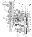
- the high-pressure injection system 1 shown in a longitudinal section in FIG. 1 has two high-pressure pumps 20 and 20a running in parallel.
- the illustrated in section first high pressure pump 20 is a with a Flange 22 having plunger 21 provided in which a pressed by a spring element 23 against an eccentrically provided on a drive shaft 41 Abicalzring 42 plunger 24 is slidably mounted.
- the stroke of the plunger 24 is designated H in FIG.
- a channel element 30 On the output side of the plunger cylinder 21, a channel element 30 is arranged, which has the plunger cylinder 21 and a common rail 10 facing, designed as a high-pressure sealing surfaces end faces 34 and 35, respectively. Between the first end face 34 and the second end face 35 extend an inlet channel 31 and an outlet channel 32, which are connected to corresponding inflow and outflow channels 13 and 14 in the common rail 10. Via the inflow channel 13, a conveying medium can be fed to the inlet channel.
- the drainage channel 14 is connected to a pressure chamber 11 provided in the common rail 10, from which connection lines 12a,..., 12d are each led to an injector 2.
- an inlet and an outlet valve 33 and 17 are provided, which are pulled or pressed by spring elements against the corresponding openings of the channels 31, 32.
- the common rail 10 has for each of the high pressure pumps 20; 20 a provided with a thread 16 Anformung 15.
- the Anformung 15 is frontally provided with a high pressure sealing surface to which the second end face 35 of the channel member 30 is connected such that the inlet and outlet channels 31, 32 in the inflow or
- Outflow channels 13 and 14 are connected in the common rail 10.
- the Anformung 15 is screwed to an internal thread having a union nut 70 having a serving for receiving the plunger 24 opening 73 (see FIG. 2).
- the output side provided on the plunger cylinder 24 flange 22, which has a channel member 30 facing high-pressure sealing surface is held by the nut 70 by an inner flange 72 and pulled against the first end face 34 of the channel member 30.
- the channel element 30 is therefore clamped by the union nut 70 between the plunger cylinder 21 and the common rail 10.
- the cap nut 70 can be detected by a tool, it has at the bottom of an example provided with six edges shaping 74.
- the high-pressure pumps 20, 20a are arranged in a housing 40 connected to the common rail 10 and sealed by a cover 50.
- the drive shaft 41 provided for driving the plungers 24 is guided into the housing 40 and stored therein in a housing 43 and in a bearing 50 provided in the housing 50 and 43, respectively.
- the cover 50 has a channel 52 connected to a connection 51, which branches into two subchannels 52a and 52b, of which the first subchannel 52a leads to the bearing 53 and from there into the housing interior 48 and the second subchannel 52b into the housing 50 provided transfer channel 45 leads, which connects the second sub-channel 52 b with the guided in the common rail 10 inflow channel 13.
- the flow rate of the delivery medium which is supplied to the connection 51 by a delivery pump (not shown here), is controlled by an intake throttle valve 46 projecting into the transfer channel 45, which is connected to an actuator 47 mounted on the housing 40.
- This arrangement requires no additional components, but only a corresponding configuration of the receiving portion on the housing 40.
- the guided into the housing interior 48 conveying medium, which serves to lubricate the drive shaft 41 and the plunger 24 is from the housing 40 through an outlet port 44 together with the conveying medium led away, which may have leaked in small quantities from the high pressure pumps 20, 20a.
- the high pressure injection system 1 shown in Fig. 1 functions as follows. Downstream of Saugdrosselventils 46, the fluid flows through the transfer channel 45, provided in the common rail 10 inlet channel 13 and provided in the channel member 30 inlet channel 31 to the inlet valve 33, which opens as soon as the pressure in the interior of the plunger cylinder 21, upon extension of the plunger 24 decreases , When retracting the plunger 24, the pumped into the interior 25 of the plunger 21 pumped medium is pressed against the inlet valve 33, which closes the inlet channel 31, and on the other hand via the outlet channel 32 of the channel member 30 to the outlet valve 17, which opens and the fluid to the pressure chamber 11 of the common rail 10 passes. Depending on the speed of the drive shaft 41, therefore, delivery medium is introduced into the pressure chamber 11 of the common rail 10.
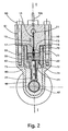
- Fig. 2 shows the high pressure injection system 1 in a cross section along the registered in Fig. 1 line II-II. It can be seen that the common rail 10 is connected by screws 60 which are screwed through holes 61 in the common rail 10 in threaded holes 62 of the housing 40 with this. Also clearly visible is the assembly of the plunger cylinder 21 and the channel element 30, which is surrounded and held by the union nut 70 connected to an internal thread 71 with the external thread 16 of the Anformung 15. It is particularly advantageous that the biasing force for sealing the resulting at the end faces 34 and 35 of the channel member 30 compounds through the inner flange 72 of the union nut 70 over the entire circumference uniformly on the outer flange 22 of the plunger 21 is transmitted.
- An increase in the surface pressure is advantageously achieved with the channel element 300 shown in FIGS. 3 and 5, which is preferably designed.
- the increase in the surface pressure is achieved by reducing the bonding surfaces of the interconnected components. As shown in FIG. 3 and FIG. 5, it is preferable that those at the end faces 340 and 350 of the channel member 300 Reduced connecting surfaces reduced. This happens, for example, in that circular grooves 305, 306 are preferably introduced into the channel element 300 at the edges of the end faces 340 and 350. Of course, the front sides of the adjacent components 15, 21 can be processed accordingly. From Fig. 4a and Fig.
- the channels 31, 32 and valves 33 provided therein are to be considered.
- a centering or a displacement of these parts 31, 32, 33 in the center of the end faces 34, 35 of the channel element 30 allows to introduce wider grooves 305 in the end faces 34, 35 and to further increase the surface pressure.
- the arrangement of the inlet valve 330 shown in Fig. 3a within the inlet channel 310 allows a more advantageous centering of the channels 310, 320 of the channel element 300, since no additional space is required for the inlet valve 330.
- a comparison of the channel elements 30, 300 of FIG. 4 and FIG. 5 also shows, that the course of the inlet channel 310 provided with the inlet valve 330 is significantly simplified, resulting in a reduction of the production expenditure of the channel element 300.
- the inlet valve 330 shown in FIG. 3a has a hollow shaft 331 provided with a channel 332.
- the inner space 332 of the hollow shaft or intake valve 330 is, as soon as the plunger 334 is lifted off its support surface, connected through openings 333 to the interior 250 of the plunger cylinder 210 so that the fluid can enter the cylinder space 250 when the plunger 24 is descending.
- the inlet valve 330 which has on the side facing away from the punch 334 a holder 335, which is pulled upwards by a valve spring 336 inserted into a cylindrical extension 307 of the inlet channel 310, can also be used advantageously in other conveyor systems, independently of the high-pressure injection system described above ,
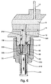
- the channel element 30; 300 are provided with one or more bolts 80, which, as shown in Figure 6, in bores 81, 82 and 83 are used in the Anformung 15; 150, in the channel member 30; 300 and in the plunger cylinder 21; 210 are provided.
- channel elements 30, 300 are shown having an inlet and an outlet channel 31; 310 and 32, respectively; 320.
- the invention is also applicable to systems in which the supply of fuel to the high-pressure pump 20 is not via the common rail and the channel element, but e.g. is done by a directly connected to the high-pressure pump 20 line.
- the high-pressure injection system 1 can be advantageously used with various common rails.
- the common rail 10 a shown there has a shortened body and a high-pressure outlet 120.
Landscapes
- Engineering & Computer Science (AREA)
- Chemical & Material Sciences (AREA)
- Combustion & Propulsion (AREA)
- Mechanical Engineering (AREA)
- General Engineering & Computer Science (AREA)
- Fuel-Injection Apparatus (AREA)
Claims (12)
- Système d'injection à haute pression (1) pour des moteurs à combustion avec une pompe à haute pression (20, 20a) qui présente un cylindre plongeur (21, 210) et avec un élément de canal (30, 300) disposé côté sortie du cylindre plongeur (21, 210), lequel élément de canal présente un canal d'évacuation (32, 320) s'étendant entre ses côtés avant (34, 340 ; 35, 350) et relié en écoulement à un espace de transport (25, 250) du cylindre plongeur (21, 210) et au moins des parties d'une vanne d'évacuation (17, 330), le premier côté avant (34, 340), tourné vers le cylindre plongeur (21, 210), de l'élément de canal (30, 300) étant conçu au moins partiellement comme une surface d'étanchéité à haute pression plane et s'appuyant sur une surface d'étanchéité à haute pression plane du cylindre plongeur (21, 210), et avec un élément de conduite à haute pression (10, 10a) disposé côté sortie de l'élément de canal (30, 300), caractérisé en ce que l'élément de conduite à haute pression (10, 10a) présente une surface d'étanchéité à haute pression plane, laquelle s'appuie sur le second côté avant (35, 350) également conçu comme une surface d'étanchéité à haute pression plane de l'élément de canal (30, 300) et en ce que l'élément de canal (30, 300) est serré entre le cylindre plongeur (21, 210) et l'élément de conduite à haute pression (10, 10a).
- Système d'injection à haute pression (1) selon la revendication 1, caractérisé en ce que le cylindre plongeur (21, 210) est tendu à l'aide d'un élément de fixation (70), qui s'applique en entourant l'élément de canal (30, 300) d'une part sur le cylindre plongeur (21, 210) et d'autre part sur l'élément de conduite à haute pression (10 , 10a), avec l'élément de conduite à haute pression (10, 10a).
- Système d'injection à haute pression (1) selon la revendication 2, caractérisé en ce que l'élément de fixation (70) est un écrou raccord, qui s'applique avec une bride intérieure (72) sur le cylindre plongeur (21, 210) et est vissé avec son filetage (71) avec l'élément de conduite à haute pression (10, 10a).
- Système d'injection à haute pression (1) selon la revendication 3, caractérisé en ce que la surface d'étanchéité à haute pression de l'élément de conduite à haute pression (10, 10a) est réalisée sur le côté avant d'une partie formée (15, 150) cylindrique de l'élément de conduite à haute pression (10, 10a), qui présente un filetage extérieur (16), lequel coopère avec le filetage intérieur (71) prévu sur l'écrou raccord (70).
- Système d'injection à haute pression (1) selon l'une quelconque des revendications 1 à 4, caractérisé en ce que l'espace de transport (25, 250) de la pompe à haute pression (20, 20a) est disposé dans un espace de cylindre du cylindre plongeur (21, 210) et est délimité côté sortie par le premier côté avant (34, 340) de l'élément de canal (30, 300), l'espace de cylindre présentant de préférence un diamètre constant.
- Système d'injection à haute pression (1) selon l'une quelconque des revendications 1 à 5, caractérisé en ce que l'élément de canal (30, 300) présente un canal d'entrée (31, 310) s'étendant entre les côtés avant (34, 340 ; 35, 350), qui est relié d'une part par un canal d'arrivée (13) agencé dans l'élément de conduite à haute pression (10, 10a) et d'autre part à l'espace de transport (25, 250) de la pompe à haute pression (20, 20a), et qui présente de préférence au moins des parties d'une vanne d'entrée (33 ; 330).
- Système d'injection à haute pression (1) selon la revendication 6, caractérisé en ce que le canal d'entrée (310) de l'élément de canal (300) est doté d'une vanne d'entrée (330), qui présente une tige creuse (331) appropriée pour la conduite du fluide de transport ainsi que des ouvertures de sortie (333) se raccordant à cette tige.
- Système d'injection à haute pression (1) selon l'une quelconque des revendications 1 à 7, caractérisé en ce que des surfaces de contact sont formées par l'appui l'une sur l'autre des surfaces d'étanchéité à haute pression de composants (21 ; 210, 300 ; 10) voisins et en ce que la surface de contact entre l'élément de canal (300) et le cylindre plongeur (21, 210) sur un côté et/ou la surface de contact entre l'élément de canal (300) et la partie formée (15, 150) de l'élément de conduite à haute pression (10, 10a) sur l'autre côté est inférieure à des surfaces de section, disposées parallèlement à la surface de contact, des composants (21 ; 210, 300 ; 10, 10a) qui se touchent dans la surface de contact.
- Système d'injection à haute pression (1) selon l'une quelconque des revendications 1 à 8, caractérisé en ce qu'un boîtier (40) relié de façon étanche à l'élément de conduite à haute pression (10, 10a) est prévu avec un espace intérieur de boîtier (48), dans lequel sont disposés la pompe à haute pression (20, 20a) et au moins partiellement son entraînement (41, 42), un fluide de transport, de préférence une partie du combustible destinée au moteur à combustion étant introduite dans l'espace intérieur de boîtier (48) pour le graissage d'éléments d'entraînement et d'éléments de pompe.
- Système d'injection à haute pression (1) selon l'une quelconque des revendications 1 à 9 avec une pompe à haute pression (20, 20a) avec un boîtier (40) et avec un élément de conduite à haute pression (10, 10a) disposé côté sortie de la pompe à haute pression (20, 20a), caractérisé en ce que dans une paroi du boîtier (40) est prévu un canal de transfert (45) relié à l'espace de transport (25, 250) de la pompe à haute pression (20, 20a) pour un fluide de transport, dont le débit peut être réglé au moyen d'un organe d'étranglement d'aspiration avec vanne d'étranglement d'aspiration (46) et actionneur (47), qui est fixé de préférence sur le boîtier (40).
- Système d'injection à haute pression (1) selon la revendication 4, caractérisé en ce que le cylindre plongeur (210), l'élément de canal (300) et la partie formée (150) sont dotés de perçages (81, 82, 83), dans lesquels est inséré un boulon (80) servant à l'orientation de ces parties (150, 210, 300).
- Système d'injection à haute pression (1) selon l'une quelconque des revendications 1 à 11, caractérisé en ce que l'élément de conduite à haute pression (10) est une rampe d'injection commune (10).
Applications Claiming Priority (2)
| Application Number | Priority Date | Filing Date | Title |
|---|---|---|---|
| CH212299 | 1999-11-19 | ||
| CH212299 | 1999-11-19 |
Publications (3)
| Publication Number | Publication Date |
|---|---|
| EP1101931A2 EP1101931A2 (fr) | 2001-05-23 |
| EP1101931A3 EP1101931A3 (fr) | 2004-04-28 |
| EP1101931B1 true EP1101931B1 (fr) | 2006-08-30 |
Family
ID=4226399
Family Applications (1)
| Application Number | Title | Priority Date | Filing Date |
|---|---|---|---|
| EP00122678A Expired - Lifetime EP1101931B1 (fr) | 1999-11-19 | 2000-10-18 | Système d'injection à haute pression avec common rail |
Country Status (4)
| Country | Link |
|---|---|
| US (2) | US6330876B1 (fr) |
| EP (1) | EP1101931B1 (fr) |
| JP (1) | JP3737355B2 (fr) |
| DE (1) | DE50013384D1 (fr) |
Families Citing this family (29)
| Publication number | Priority date | Publication date | Assignee | Title |
|---|---|---|---|---|
| EP1101931B1 (fr) * | 1999-11-19 | 2006-08-30 | CRT Common Rail Technologies AG | Système d'injection à haute pression avec common rail |
| JP2001214829A (ja) * | 2000-01-31 | 2001-08-10 | Bosch Automotive Systems Corp | 燃料噴射ポンプ |
| DE10036868B4 (de) * | 2000-07-28 | 2004-07-29 | Robert Bosch Gmbh | Injektor für ein einen Hochdrucksammelraum umfassendes Einspritzsystem |
| DE10057683B4 (de) * | 2000-11-21 | 2005-10-06 | Robert Bosch Gmbh | Kraftstoffeinspritzeinrichtung |
| EP1454055B1 (fr) * | 2001-12-01 | 2005-11-02 | Robert Bosch Gmbh | Pompe a piston radiaux a graissage force |
| DE10247524B4 (de) * | 2002-10-11 | 2004-08-12 | Siemens Ag | Kraftstoffverteiler |
| DE10314029A1 (de) | 2003-03-28 | 2004-10-07 | Deutz Ag | Brennkraftmaschine mit einem Speichereinspritzsystem |
| DE60319968T2 (de) * | 2003-06-20 | 2009-04-16 | Delphi Technologies, Inc., Troy | Kraftstoffsystem |
| EP1687524B1 (fr) * | 2003-11-28 | 2008-07-02 | Ganser-Hydromag Ag | Pompe d'alimentation haute pression destinee a des moteurs a combustion interne |
| ITBO20040323A1 (it) * | 2004-05-20 | 2004-08-20 | Magneti Marelli Powertrain Spa | Metodo di iniezione diretta di carburante in un motore a combustione interna |
| US7690353B2 (en) * | 2007-11-30 | 2010-04-06 | Caterpillar Inc. | Synchronizing common rail pumping events with engine operation |
| DE602008004620D1 (de) * | 2008-02-19 | 2011-03-03 | Continental Automotive Gmbh | Kupplungsvorrichtung |
| EP2093413B1 (fr) * | 2008-02-19 | 2011-01-12 | Continental Automotive GmbH | Dispositif de couplage |
| DE602008004621D1 (de) * | 2008-02-19 | 2011-03-03 | Continental Automotive Gmbh | Kupplungsvorrichtung |
| EP2093414B1 (fr) * | 2008-02-19 | 2011-07-20 | Continental Automotive GmbH | Dispositif de couplage |
| EP2208883B1 (fr) * | 2009-01-19 | 2015-07-22 | Continental Automotive GmbH | Dispositif de couplage |
| ITTO20090715A1 (it) * | 2009-09-21 | 2011-03-22 | Torino Politecnico | Gruppo pompa perfezionato per un apparato di iniezione di un motore a combustione interna |
| DE102010001252A1 (de) | 2010-01-27 | 2011-07-28 | Robert Bosch GmbH, 70469 | Kraftstoffeinspritzsystem mit integriertem Hochdruckspeicher an einem Zylinderkopf |
| US8561593B2 (en) * | 2010-03-05 | 2013-10-22 | Caterpillar Inc. | Range of engines using common rail fuel system with pump and rail assemblies having common components |
| DE102010020578A1 (de) * | 2010-05-14 | 2011-11-17 | Bayerische Motoren Werke Aktiengesellschaft | Vorrichtung zum Antrieb eines Nebenaggregates |
| DE102011005096A1 (de) * | 2011-03-04 | 2012-09-06 | Man Diesel & Turbo Se | Verbrennungsmotor |
| DE102011076020A1 (de) | 2011-05-18 | 2012-11-22 | Robert Bosch Gmbh | Hochdruckeinspritzsystem |
| CN104296934B (zh) * | 2014-10-30 | 2017-04-05 | 泉州市双庆工程机械有限公司 | 一种液压阀门总装密封试验台的上料夹紧装置 |
| GB201516704D0 (en) * | 2015-09-21 | 2015-11-04 | Delphi Int Operations Lux Srl | Fuel pump assembly |
| CN106640456B (zh) * | 2016-12-27 | 2018-05-29 | 清华大学 | 用于内燃机燃油喷射系统的泵轨体 |
| KR102162327B1 (ko) | 2019-04-23 | 2020-10-06 | 박장균 | 공기주입이 가능한 다기능 에어쿠션 |
| DE102021102709A1 (de) | 2021-02-05 | 2022-08-11 | Joachim Risse | Hochdruckpumpe |
| US12545438B2 (en) | 2021-02-19 | 2026-02-10 | Cesaroni Aerospace Incorporated | Rocket motor |
| GB2613564B (en) * | 2021-12-03 | 2023-12-20 | Delphi Tech Ip Ltd | Fuel pump |
Family Cites Families (38)
| Publication number | Priority date | Publication date | Assignee | Title |
|---|---|---|---|---|
| GB2028916B (en) * | 1978-08-23 | 1982-09-22 | Lucas Industries Ltd | Fuel supply system for internal combustion engine |
| JPS5552553U (fr) * | 1978-09-30 | 1980-04-08 | ||
| JPS6036779Y2 (ja) * | 1981-03-03 | 1985-10-31 | 三菱重工業株式会社 | 吸戻しピストン装置 |
| DE3141654A1 (de) * | 1981-10-21 | 1983-05-05 | L'Orange GmbH, 7000 Stuttgart | Kraftstoffeinspritzpumpe, insbesondere fuer eine dieselbrennkraftmaschine |
| JPS58116757U (ja) * | 1982-02-03 | 1983-08-09 | 株式会社小松製作所 | デイ−ゼルエンジンの燃料噴射管接続装置 |
| JPS60182353A (ja) * | 1984-02-28 | 1985-09-17 | Mitsubishi Heavy Ind Ltd | 半導体ウエハの研摩方法 |
| JPS61132769A (ja) * | 1984-11-29 | 1986-06-20 | Mitsubishi Heavy Ind Ltd | 燃料噴射ポンプ |
| JPH07122422B2 (ja) * | 1986-05-02 | 1995-12-25 | 日本電装株式会社 | 燃料噴射装置 |
| US5197438A (en) * | 1987-09-16 | 1993-03-30 | Nippondenso Co., Ltd. | Variable discharge high pressure pump |
| JPH081160B2 (ja) * | 1988-09-19 | 1996-01-10 | 株式会社ゼクセル | 燃料噴射弁 |
| JPH0341279A (ja) | 1989-07-05 | 1991-02-21 | Mitsubishi Electric Corp | パイロット式電磁弁 |
| JPH0754703Y2 (ja) * | 1989-08-30 | 1995-12-18 | 株式会社小松製作所 | 逆止弁 |
| JPH04183968A (ja) * | 1990-11-16 | 1992-06-30 | Nippondenso Co Ltd | 燃料噴射ポンプ |
| FI93985C (fi) * | 1991-04-17 | 1995-06-26 | Waertsilae Diesel Int | Polttoaineen ruiskutuspumpun asennus- ja kytkentäjärjestely |
| US5524912A (en) | 1993-03-01 | 1996-06-11 | Laub; Michael J. | All season skate |
| AU6785994A (en) * | 1993-05-06 | 1994-12-12 | Cummins Engine Company Inc. | Variable displacement high pressure pump for common rail fuel injection systems |
| US5678521A (en) * | 1993-05-06 | 1997-10-21 | Cummins Engine Company, Inc. | System and methods for electronic control of an accumulator fuel system |
| JPH07167009A (ja) * | 1993-12-14 | 1995-07-04 | Yamaha Motor Co Ltd | エンジンへの燃料供給装置 |
| JP3077738B2 (ja) * | 1994-04-28 | 2000-08-14 | 株式会社デンソー | 高圧サプライポンプ |
| US5606603A (en) * | 1995-01-05 | 1997-02-25 | Lucent Technologies Inc. | System and apparatus for recording and displaying received information at a remote location using premises recording unit |
| JP3849067B2 (ja) * | 1995-03-30 | 2006-11-22 | ボッシュ株式会社 | 燃料噴射ポンプ |
| JPH09317599A (ja) * | 1996-05-22 | 1997-12-09 | Usui Internatl Ind Co Ltd | コモンレールおよびその製造方法 |
| JPH1018941A (ja) * | 1996-07-01 | 1998-01-20 | Mitsubishi Electric Corp | 可変吐出量高圧ポンプ |
| DE69731241T2 (de) * | 1996-07-05 | 2006-03-02 | Nippon Soken, Inc., Nishio | Hochdruckpumpe für Dieselmotor-Kraftstoffeinspritzsystem |
| JP3310871B2 (ja) * | 1996-07-08 | 2002-08-05 | 三菱電機株式会社 | 燃料噴射装置 |
| DE19646581A1 (de) * | 1996-11-12 | 1998-05-14 | Bosch Gmbh Robert | Kraftstoffeinspritzsystem |
| JP3385415B2 (ja) * | 1997-01-30 | 2003-03-10 | 日野自動車株式会社 | 高圧燃料パイプの接続構造 |
| JP3749013B2 (ja) * | 1997-03-03 | 2006-02-22 | 臼井国際産業株式会社 | コモンレールおよびその製造方法 |
| JPH112166A (ja) * | 1997-06-13 | 1999-01-06 | Zexel Corp | 電磁弁制御型燃料噴射ポンプ |
| DE19729788A1 (de) * | 1997-07-11 | 1999-01-14 | Bosch Gmbh Robert | Radialkolbenpumpe zur Kraftstoffhochdruckversorgung |
| US6135092A (en) * | 1997-10-29 | 2000-10-24 | General Motors Corporation | Fuel injection system |
| EP0915252A3 (fr) | 1997-11-05 | 2000-03-15 | SIG Schweizerische Industrie-Gesellschaft | Système d'injection par alimentation commune des injecteurs |
| JP3492503B2 (ja) * | 1997-11-11 | 2004-02-03 | 日野自動車株式会社 | 管継手 |
| JP2000035149A (ja) * | 1998-07-21 | 2000-02-02 | Nippon Soken Inc | 流量制御用の電磁弁 |
| EP0990792A3 (fr) * | 1998-09-30 | 2003-05-21 | CRT Common Rail Technologies AG | Système d'injection de carburant de type Common-Rail |
| WO2000063551A1 (fr) * | 1999-04-16 | 2000-10-26 | Caterpillar Inc. | Pompe d'alimentation variable et systeme de rampe d'injection a carburant utilisant celle-ci |
| DE50009529D1 (de) * | 1999-05-31 | 2005-03-24 | Crt Common Rail Tech Ag | Hochdruckförderpumpe |
| EP1101931B1 (fr) * | 1999-11-19 | 2006-08-30 | CRT Common Rail Technologies AG | Système d'injection à haute pression avec common rail |
-
2000
- 2000-10-18 EP EP00122678A patent/EP1101931B1/fr not_active Expired - Lifetime
- 2000-10-18 DE DE50013384T patent/DE50013384D1/de not_active Expired - Lifetime
- 2000-11-17 US US09/714,188 patent/US6330876B1/en not_active Expired - Lifetime
- 2000-11-17 JP JP2000351127A patent/JP3737355B2/ja not_active Expired - Fee Related
-
2001
- 2001-10-16 US US09/977,329 patent/US6745753B2/en not_active Expired - Lifetime
Also Published As
| Publication number | Publication date |
|---|---|
| JP3737355B2 (ja) | 2006-01-18 |
| US6745753B2 (en) | 2004-06-08 |
| JP2001173537A (ja) | 2001-06-26 |
| DE50013384D1 (de) | 2006-10-12 |
| EP1101931A2 (fr) | 2001-05-23 |
| EP1101931A3 (fr) | 2004-04-28 |
| US6330876B1 (en) | 2001-12-18 |
| US20020017278A1 (en) | 2002-02-14 |
Similar Documents
| Publication | Publication Date | Title |
|---|---|---|
| EP1101931A2 (fr) | Système d'injection à haute pression avec common rail | |
| EP1989436B1 (fr) | Dispositif d'injection de carburant pour moteur a combustion interne | |
| EP1314883B1 (fr) | Système d'alimentation en carburant à rampe commune pour un moteur à combustion interne à plusieurs cylindres | |
| EP0461212B1 (fr) | Pompe d'injection de carburant a commande electrique pour moteurs a combustion interne, en particulier pompe d'injection combinee avec l'injecteur | |
| EP2798191B1 (fr) | Soupape de décharge de carburant pour un injecteur de carburant et injecteur de carburant équipé d'une soupape de décharge de carburant | |
| DE4320620B4 (de) | Kraftstoffeinspritzeinrichtung für Brennkraftmaschinen | |
| EP1561028B1 (fr) | Pompe haute pression d'alimentation en carburant comprenant un clapet a bille dans l'admission basse pression | |
| DE102006000035A1 (de) | Fluideinspritzventil | |
| DE102008041594A1 (de) | Kraftstoff-Hochdruckpumpe für eine Brennkraftmaschine | |
| WO2013092968A2 (fr) | Pompe, en particulier pompe carburant haute pression pour un dispositif d'injection de carburant | |
| EP1736662B1 (fr) | Clapet anti-retour, notamment pour une pompe à haute pression d'un dispositif d'injection de combustible pour un moteur à combustion interne | |
| WO2010012525A1 (fr) | Dispositif d'alimentation en carburant pour moteur à combustion interne | |
| WO2021185508A1 (fr) | Pompe à carburant haute pression | |
| DE10154133C1 (de) | Kraftstoffsystem | |
| EP1361357A2 (fr) | Pompe à carburant notamment pour un moteur à combustion interne et à injection directe | |
| EP1910663B1 (fr) | Systeme d'injection de carburant pour moteur a combustion interne a injection directe de carburant | |
| EP1784571B1 (fr) | Pompe haute pression pour un systeme d'injection de carburant d'un moteur a combustion interne | |
| EP1671029B1 (fr) | Dispositif d'injection de carburant, notamment pour un moteur a combustion interne a injection directe de carburant | |
| DE19920997B4 (de) | Radialkolbenpumpe | |
| DE102008062518B4 (de) | Hochdruckpumpe | |
| DE10154552A1 (de) | Kraftstoff-Pumpeinrichtung für ein Kraftstoffsystem einer Brennkraftmaschine sowie Kraftstoffsystem | |
| EP3054144B1 (fr) | Vanne de decharge de pompe haute pression, en particulier pompe enfichable et pompe haute pression comprenant une telle vanne de decharge | |
| EP1582740B1 (fr) | Pompe à haute-pression avec accumulateur haute-pression intégré | |
| DE102019209682A1 (de) | Hochdruckpumpe und Einspritzsystem | |
| EP1325228B1 (fr) | Soupape d'injection avec piston de pompe |
Legal Events
| Date | Code | Title | Description |
|---|---|---|---|
| PUAI | Public reference made under article 153(3) epc to a published international application that has entered the european phase |
Free format text: ORIGINAL CODE: 0009012 |
|
| AK | Designated contracting states |
Kind code of ref document: A2 Designated state(s): AT BE CH CY DE DK ES FI FR GB GR IE IT LI LU MC NL PT SE |
|
| AX | Request for extension of the european patent |
Free format text: AL;LT;LV;MK;RO;SI |
|
| RIC1 | Information provided on ipc code assigned before grant |
Ipc: 7F 02M 59/44 B Ipc: 7F 02M 39/02 B Ipc: 7F 02M 55/02 A Ipc: 7F 02M 63/02 B |
|
| PUAL | Search report despatched |
Free format text: ORIGINAL CODE: 0009013 |
|
| RIC1 | Information provided on ipc code assigned before grant |
Ipc: 7F 02M 63/02 B Ipc: 7F 02M 39/02 A Ipc: 7F 02M 55/02 B Ipc: 7F 02M 59/44 B |
|
| AK | Designated contracting states |
Kind code of ref document: A3 Designated state(s): AT BE CH CY DE DK ES FI FR GB GR IE IT LI LU MC NL PT SE |
|
| AX | Request for extension of the european patent |
Extension state: AL LT LV MK RO SI |
|
| 17P | Request for examination filed |
Effective date: 20040805 |
|
| AKX | Designation fees paid |
Designated state(s): DE ES FR GB IT |
|
| 17Q | First examination report despatched |
Effective date: 20050418 |
|
| GRAP | Despatch of communication of intention to grant a patent |
Free format text: ORIGINAL CODE: EPIDOSNIGR1 |
|
| GRAS | Grant fee paid |
Free format text: ORIGINAL CODE: EPIDOSNIGR3 |
|
| GRAA | (expected) grant |
Free format text: ORIGINAL CODE: 0009210 |
|
| AK | Designated contracting states |
Kind code of ref document: B1 Designated state(s): DE ES FR GB IT |
|
| PG25 | Lapsed in a contracting state [announced via postgrant information from national office to epo] |
Ref country code: IT Free format text: LAPSE BECAUSE OF FAILURE TO SUBMIT A TRANSLATION OF THE DESCRIPTION OR TO PAY THE FEE WITHIN THE PRESCRIBED TIME-LIMIT;WARNING: LAPSES OF ITALIAN PATENTS WITH EFFECTIVE DATE BEFORE 2007 MAY HAVE OCCURRED AT ANY TIME BEFORE 2007. THE CORRECT EFFECTIVE DATE MAY BE DIFFERENT FROM THE ONE RECORDED. Effective date: 20060830 |
|
| REG | Reference to a national code |
Ref country code: GB Ref legal event code: FG4D Free format text: NOT ENGLISH |
|
| REF | Corresponds to: |
Ref document number: 50013384 Country of ref document: DE Date of ref document: 20061012 Kind code of ref document: P |
|
| GBT | Gb: translation of ep patent filed (gb section 77(6)(a)/1977) |
Effective date: 20061115 |
|
| PG25 | Lapsed in a contracting state [announced via postgrant information from national office to epo] |
Ref country code: ES Free format text: LAPSE BECAUSE OF FAILURE TO SUBMIT A TRANSLATION OF THE DESCRIPTION OR TO PAY THE FEE WITHIN THE PRESCRIBED TIME-LIMIT Effective date: 20061211 |
|
| ET | Fr: translation filed | ||
| PLBE | No opposition filed within time limit |
Free format text: ORIGINAL CODE: 0009261 |
|
| STAA | Information on the status of an ep patent application or granted ep patent |
Free format text: STATUS: NO OPPOSITION FILED WITHIN TIME LIMIT |
|
| 26N | No opposition filed |
Effective date: 20070531 |
|
| REG | Reference to a national code |
Ref country code: FR Ref legal event code: PLFP Year of fee payment: 16 |
|
| REG | Reference to a national code |
Ref country code: FR Ref legal event code: PLFP Year of fee payment: 17 |
|
| PGFP | Annual fee paid to national office [announced via postgrant information from national office to epo] |
Ref country code: GB Payment date: 20161020 Year of fee payment: 17 Ref country code: DE Payment date: 20161020 Year of fee payment: 17 Ref country code: FR Payment date: 20161020 Year of fee payment: 17 |
|
| PGFP | Annual fee paid to national office [announced via postgrant information from national office to epo] |
Ref country code: IT Payment date: 20161024 Year of fee payment: 17 |
|
| REG | Reference to a national code |
Ref country code: DE Ref legal event code: R119 Ref document number: 50013384 Country of ref document: DE |
|
| GBPC | Gb: european patent ceased through non-payment of renewal fee |
Effective date: 20171018 |
|
| REG | Reference to a national code |
Ref country code: FR Ref legal event code: ST Effective date: 20180629 |
|
| PG25 | Lapsed in a contracting state [announced via postgrant information from national office to epo] |
Ref country code: GB Free format text: LAPSE BECAUSE OF NON-PAYMENT OF DUE FEES Effective date: 20171018 Ref country code: DE Free format text: LAPSE BECAUSE OF NON-PAYMENT OF DUE FEES Effective date: 20180501 |
|
| PG25 | Lapsed in a contracting state [announced via postgrant information from national office to epo] |
Ref country code: FR Free format text: LAPSE BECAUSE OF NON-PAYMENT OF DUE FEES Effective date: 20171031 |
|
| PG25 | Lapsed in a contracting state [announced via postgrant information from national office to epo] |
Ref country code: IT Free format text: LAPSE BECAUSE OF NON-PAYMENT OF DUE FEES Effective date: 20171018 |