EP0873774A1 - Ölfilter mit einem dauermagneten anstelle eines filterpapiers - Google Patents
Ölfilter mit einem dauermagneten anstelle eines filterpapiers Download PDFInfo
- Publication number
- EP0873774A1 EP0873774A1 EP96940154A EP96940154A EP0873774A1 EP 0873774 A1 EP0873774 A1 EP 0873774A1 EP 96940154 A EP96940154 A EP 96940154A EP 96940154 A EP96940154 A EP 96940154A EP 0873774 A1 EP0873774 A1 EP 0873774A1
- Authority
- EP
- European Patent Office
- Prior art keywords
- oil
- magnetic
- filter
- oil filter
- magnets
- Prior art date
- Legal status (The legal status is an assumption and is not a legal conclusion. Google has not performed a legal analysis and makes no representation as to the accuracy of the status listed.)
- Granted
Links
Images




Classifications
-
- B—PERFORMING OPERATIONS; TRANSPORTING
- B01—PHYSICAL OR CHEMICAL PROCESSES OR APPARATUS IN GENERAL
- B01D—SEPARATION
- B01D35/00—Filtering devices having features not specifically covered by groups B01D24/00 - B01D33/00, or for applications not specifically covered by groups B01D24/00 - B01D33/00; Auxiliary devices for filtration; Filter housing constructions
- B01D35/06—Filters making use of electricity or magnetism
-
- B—PERFORMING OPERATIONS; TRANSPORTING
- B03—SEPARATION OF SOLID MATERIALS USING LIQUIDS OR USING PNEUMATIC TABLES OR JIGS; MAGNETIC OR ELECTROSTATIC SEPARATION OF SOLID MATERIALS FROM SOLID MATERIALS OR FLUIDS; SEPARATION BY HIGH-VOLTAGE ELECTRIC FIELDS
- B03C—MAGNETIC OR ELECTROSTATIC SEPARATION OF SOLID MATERIALS FROM SOLID MATERIALS OR FLUIDS; SEPARATION BY HIGH-VOLTAGE ELECTRIC FIELDS
- B03C1/00—Magnetic separation
- B03C1/02—Magnetic separation acting directly on the substance being separated
- B03C1/28—Magnetic plugs and dipsticks
- B03C1/286—Magnetic plugs and dipsticks disposed at the inner circumference of a recipient, e.g. magnetic drain bolt
-
- B—PERFORMING OPERATIONS; TRANSPORTING
- B03—SEPARATION OF SOLID MATERIALS USING LIQUIDS OR USING PNEUMATIC TABLES OR JIGS; MAGNETIC OR ELECTROSTATIC SEPARATION OF SOLID MATERIALS FROM SOLID MATERIALS OR FLUIDS; SEPARATION BY HIGH-VOLTAGE ELECTRIC FIELDS
- B03C—MAGNETIC OR ELECTROSTATIC SEPARATION OF SOLID MATERIALS FROM SOLID MATERIALS OR FLUIDS; SEPARATION BY HIGH-VOLTAGE ELECTRIC FIELDS
- B03C1/00—Magnetic separation
- B03C1/02—Magnetic separation acting directly on the substance being separated
- B03C1/28—Magnetic plugs and dipsticks
- B03C1/288—Magnetic plugs and dipsticks disposed at the outer circumference of a recipient
-
- B—PERFORMING OPERATIONS; TRANSPORTING
- B03—SEPARATION OF SOLID MATERIALS USING LIQUIDS OR USING PNEUMATIC TABLES OR JIGS; MAGNETIC OR ELECTROSTATIC SEPARATION OF SOLID MATERIALS FROM SOLID MATERIALS OR FLUIDS; SEPARATION BY HIGH-VOLTAGE ELECTRIC FIELDS
- B03C—MAGNETIC OR ELECTROSTATIC SEPARATION OF SOLID MATERIALS FROM SOLID MATERIALS OR FLUIDS; SEPARATION BY HIGH-VOLTAGE ELECTRIC FIELDS
- B03C2201/00—Details of magnetic or electrostatic separation
- B03C2201/18—Magnetic separation whereby the particles are suspended in a liquid
Definitions
- This invention pertains to oil filters that use permanent magnets, instead of (or as an adjunct to) paper filters, to remove micro particles (between 40 micro millimeter and about 1 micro millimeter) that cannot be removed by conventional paper filter, as well as to prevent the degradation process of oil with the magnetic ray.
- This will extend the life of instruments, improve fuel efficiency, reduce air pollution, and reduce waste products fiom disposing the filter cartridges by replacing the conventional oil filters and strainers, which use paper filter, that are installed on automobiles, motor cycles, trains, boats, airplanes, industrial vehicles and machinery, etc.
- Contemporary or traditional oil filters are available in two types: element-exchangeable, full-flow filters and spin-on oil filters
- element exchangeable, fall-flow filter does not have a relief valve but the filter paper is replaceable.
- spin-on filters a relief valve element and casing are formed together, and the paper filter is integral to the device. Both types use paper as the primary filter element.
- the present invention makes a distinction between oil filters that use a paper filtering element and those, such as the invention, that use permanent magnets (positioned like pole to like pole, with intermingling magnetic fields) as the agent for removing microscopic metallic particles from lubricating fluid.
- Contemporary or traditional oil filters utilize temporary, paper filtering elements that cannot remove particles smaller than approximately 40 micro millimeters.
- the present invention represents an improvement in the art through its ability to remove from lubricating oil the smallest measurable metallic particles.
- permanent magnets can be used to remove microscopic metallic particles from the lubricating oil of internal combustion engines such as those used in trucks, automobiles, motorcycles, and trains, etc. But there are two different approaches to appropriating permanent magnets for this purpose. One approach is to place multiple magnets such that their North and South poles face each other and let oil flow between them.
- the new invention improves the state of the art by replacing oil filters that utilize paper filtering elements with filters that use magnets placed in repelling positions to remove metallic particles from engine oil.
- the purpose of this invention is to remove microscopic metal particles from engine oil, to stabilize oil chemistry by preventing heat induced bond breakage, to maintain oil viscosity and prevent oil degradation. All this keeps oil in optimal condition for a longer time, which in turn keeps internal combustion engines, transmissions, decelerators and hydraulic machinery in optimal condition which leads to improved fuel economy, cleaner exhaust and longer engine life.
- the repelling magnet oil filter lasts the life of the vehicle and simply needs to be cleaned every 30,000 or 40,000 miles.
- Collateral benefits of the invention includes the annual saving of hundreds of thousands of tons of timber ordinarily used in the manufacture of paper filters, the reduction of the waste disposal requirements associated with used paper filters or filter elements and the reduction of air pollution caused by toxic exhaust emissions.
- the first particular of this invention is to replace paper elements of oil filters with disk shape magnets.
- the multiple number of magnet sides are yoke processed.
- the magnets are positioned the same distance from each other with magnetic fields opposed -- North pole to North pole, and South pole to South pole.
- the distance between magnets should be at most one half of the distance the same magnets keep apart from each other when placed vertically stacked with repelling sides facing against each other (the lower magnet must be placed on a non-magnetic material).
- Placed between the magnets are position supporters composed of non-magnetic material drilled with holes to let oil flow through.
- This array of multiple permanent magnets stacked equidistant in polar opposition by a non-magnetic, porous framework around a central tube. It is an oil filter that uses permanent magnets in place of paper filters for tile purpose of preventing wearing at lubricated areas by attracting magnetic micro particles in lubricant and preventing oil degradation by the use of magnetic field.
- the second part of this invention is to replace paper elements of oil filter with rectangular cubic permanent magnet rods which has poles sideways.
- the multiple magnet rods are placed on a circle with only South or North poles facing toward the center of the circle; the other pole facing away from the circle.
- the magnets are positioned equidistant from a central point and the distance between magnets should be no more than the distance the magnets keep apart from each other when one is placed above the other with repelling poles facing against each other. (this time, the lower magnet must be placed on a non-magnetic material).
- Placed inside of the magnet ring is a plate interspersed with holes to create turbulence in oil flow.
- the lengthwise ends of the ring of magnets are placement framework to keep the magnets in place.
- This combination of multiple permanent magnents forms a filtering element maintained in a non-magnetic element case. It is an oil filter that uses permanent magnets in place of paper filter for the purpose of preventing wearing at lubricated areas by attracting magnetic micro particles in lubricant and preventing oil degradation by the use of magnetic field.
- the example uses for this new oil filter are (1) an oil filter integrally consisting of the non-magnetic oil element case and the filter element made up with multiple number of disk and/or rod shaped permanent magnets (both to be called magnet filter element from here), such as the magnet filter element encased in a non-magnetic oil element case where the magnet element is fixed by a spring, (2) Oil filters consisting of a magnet filter element and a non-magnetic oil element case that is not fixed on the such devices as internal combustion system, transmission, decelerator, hydraulic machinery, from which magnet filter elements are removable. (3) Oil filters consisting of a magnetic filter element and a non-magnetic oil element case that is removably fixed onto such devices as internal combustion engines, transmissions, decelerators and hydraulic machinery.
- This invention which uses magnet filter element in place of paper filter elements in the oil filter, by placing each magnets close together with opposing poles facing each other to let oil flow through them in order to remove metal particles and to prevent degradation of oil by the use of magnetic field.
- the objectives of this invention are attained by ensuring attraction of the magnetic micro particles and by extending the time for the oil to flow through the magnetic field.
- This invention is, along with the above mentioned two particulars, to replace paper elements in the oil filter with repelling large magnets (N to N, S to S) utilizing the space that would be occupied by paper filter. This is to ensure removal of magnetic micro particles in the oil with large areas of attraction and to extend the time between cleaning of the parts. And, by placing the magnets and the repelling magnetic fields closer together, it has wider effective area, hence, extending the time in which the oil goes through the magnetic field.
- an indirect, preventive benefit of the invention (and its reduction of the magnetic particles mixed with the oil) is improved sealing between cylinder and piston walls which minimizes the blow-by gas commonly associated with a loss of compression.
- the invention is applicable to any device that uses a reservoir of oil to lubricate its moving parts, such as internal combustion system, transmission, decelerator, hydraulic machinery, etc. on water or wind powered plants, refrigerators, steam turbines, automobiles, motorcycles, rail transporters, airplanes, boats, load movers, such as forklifts, power tools and industrial machinery.
- the newly invented paperless oil filter utilizing permanent magnets consists of multiple disc or rectangular cube-shaped permanent magnets positioned propinquitously in repelling position (N to N, S to S) around a point.
- N to N, S to S repelling position
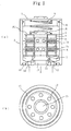
- FIG. 1 indicates the application of the oil filter not using a filter paper but using permanent magnets as a spin-on oil filter for automobiles.
- (a) in FIG. 1 is a cross-sectional view and (b) is the base view of the filter.
- FIG. 1 describes a sample oil filter in which the non-magnetic oil element casing and the disk-shaped, magnetic filter elements are integral to each other.
- the filter elements are constructed as described in the same diagram, and referred to as disk-shaped magnet element A1.
- the center-holed, disk-shaped permanent magnets 4 have flat, polar sides attached to yokes 3 .
- the element set bolt 7 is placed through the center holes of said magnets. Opposing, like magnetic poles are positioned so that their magnetic fields repel each other continually. Between the adjacent, disc-shaped magnets reside supportive structures 5 permeated by holes 14 through which oil flows.
- a nut 8 on the top end, and a rubber flow controller 11 is positioned on the bottom end of the element set bolt 7.
- the disk-shaped magnetic element replacement for a paper filter is designated A1.
- the outer part has a two-part structure.
- the disk-shaped magnetic element A1 which resides within the non-magnetic element case 2 is held in place by a set spring 6 above the disk-shaped magnetic element A1 and the oil element cap 1 with O-ring 9 to secure the oil element case 2.
- Embodiment No. 1 is attached to host machinery with case O-ring 10 .
- the oil element case 2 is made with non-magnetic material and there is no particular choice of material to be used.
- the group of example materials include copper metal (yellow copper, bronze phosphate, nickel silver, aluminum bronze), and aluminum and its kind, magnesium and its compound, titanium and its compound, zinc and its compound, lead and its compound, stainless steels. These materials surfaces are treated.
- FIG. 1 refers to spin-on type automobile oil filters
- the same filter can be used on motorcycles, industrial vehicles, hydraulic machinery arid air machinery, as long as similar forms of oil filters are used.
- FIG. 2 describes another embodiment of the oil filter not using a filter paper but using permanent magnets as a spin-on oil filter for automobiles.
- (a) in FIG. 1 is a cross-sectional view and (b) is the base view of the filter.
- FIG. 2 describes an oil filter in which the non-magnetic oil element casing and the magnetic filter elements, in place of paper filter elements, made up of disk-shaped magnets are integral.
- the filter elements are constructed as described in the same diagram and referred to as disk-shaped magnet element A1.
- the center-holed disk shaped permanent magnets 4 which flat polar sides attach to yokes 3.
- the element set bolt 7 is placed through the center holes in of the magnets.
- the opposing poles are positioned so that their poles continually repel each other.
- Between the adjacent disc-shaped magnets are supportive panels 5 with holes 14 for the oil to flow through.
- a nut 8 on the top end, and a rubber flow controller 11 on the bottom end of the element set bolt 7 are placed.
- This disk-shaped magnet element A1 replaces a paper filter.
- FIG. 2 depicts an embodiment that replaces a paper filter with rectangular-cube shaped magnets 25 which opposing lengthwise poles are arrayed on a circle around a point at constant intervals with the same pole facing the point and the opposite poles facing away from the point.
- the rectangular-cube shaped magnets are fixed in place with the set plate 24, top endplate 23, lower end plate 27 on each end.
- the turbulence-creating plates 29 and 30 are located within the circular array formed by the placement of the rectangular-cubic magnets 25. Surrounding the circular array formed by the rectangular-cubic magnets is a perimeter 26 with holes 36 expediting the flow of oil.
- the rectangular-cube magnets 25 are fixed in place by a set plate 24.
- a rubber anti-flowback valve 32 is positioned on the end plate 27. We will call this rectangular-cubic magnet element B1 to replace paper filter elements.
- the casing has a two-part structure.
- the rectangular-cubed magnet element B1 placed inside the non-magnetic element case 22 is held in place by set spring 28 above the rectangular-cubed magnet element B1 and the oil element cap 1 with cap O-ring 31 to close the oil element case 22.
- This procedure makes the oil filter with such characteristics as paperless filtration and strong repelling magnetic fields.
- oil enters into the oil filter through the oil intake 34, through holes 36 of outer tube 26, between rectangular-cube magnets 25, and the turbulent plates 29, 30, and exit through the outlet 35 to return to the cycle flow.
- 33 is the case O-ring.
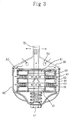
- FIG 3 indicates the application of the oil filter not using a filter paper but using permanent magnets as a full-flow element exchangeable oil filter for automobiles.
- (a) in FIG. 3 is a cross-sectional view and (b) is the base view of the filter.
- FIG. 3 describes a sample oil filter in which the non-magnetic oil element casing and the disk-shaped, magnetic filter elements are separable.
- the filter elements are constructed as described in the same diagram, and referred to as disk-shaped magnet element A2.
- the center holed, disk-shaped permanent magnets 44 have flat, polar sides attached to yokes 43.
- the inner tube 42 is placed through the center holes of said magnets. Opposing, like magnetic fields repel each other continually. Between the adjacent, disc-shaped magnets reside supportive structures 45 permeated by holes 46 through which oil flows.
- the set end plat 41 is placed on each end of the inner tube 42.
- the disk-shaped magnetic element replacement for a paper filter is designated A2.
- the disk-shaped magnetic elements A2 with non-magnetic oil element casing 49 will be installed onto the case cap 48 on the engine with a center bolt 47.
- oil enters into the oil filter through the oil intake 50, through holes 46 ill the support place 45, between poles of the disk-shaped magnets 44, and into the center bolt 47 space, and exits through the outlet 51 and returns to lubricate the host machinery.
- FIG. 3 refers to full-flow element exchangeable type automobiles oil filter
- the same filter can be used on motorcycles, industrial vehicles, hydraulic machinery and air machinery, as long as similar forms of oil filters are used.
- FIG. 4 describes another embodiment of the oil filter not using a filter paper but using permanent magnets as a full-flow element exchangeable oil filter for automobiles.
- (a) in FIG. 4 is a cross-sectional view and (b) is the base view of the filter.
- FIG. 4 describes an oil filter in which the non-magnetic oil element casing and the magnetic filter elements that are separable from each other.
- the filter elements are, in pace of paper filter elements , made up of rectangular-cube-shaped magnets 65 which opposing, lengthwise poles are arrayed on a circle around a point at constant intervals with the same pole facing the point arid the opposite poles facing away from the point.
- the rectangular-cube shaped magnets 65 are fixed in place with the set plate 61 .
- the turbulence-creating plates 69 and 70 are located within the circular array formed by the placement of the rectangular-cubic magnets 65.
- the support plate 62 with holes 63 expediting the flow of oil are fixed in place by the end plates 72.
- the filter elements constructed described here is referred to as stick-shaped magnet element B2.
- the disk-shaped magnetic elements B2 with non-magnetic oil element casing 64 will be installed onto the case cap 67 on the engine with a center bolt 66.
- oil enters into the oil filter through the oil intake 68, through holes 63 in the support plate 62, between poles of the stick-shaped magnets 65, and into the center bolt 66 space, and exits through the outlet 71 and returns to lubricate the host machinery.
- the procedure makes the oil filter with such characteristics as paperless filtration and strong repelling magnetic fields.
- the above invention refers to full-flow element exchangeable type automobiles oil filter, and among its distinct characteristics are that it replaces the disposable paper filter elements, it can be removed from the casing for a cleaning, and it produces a strong repelling magnetic field.
- FIG. 4 refers to full-flow element exchangeable type automobiles oil filter
- the same filter can be used on motorcycles, industrial vehicles, hydraulic machinery and air machinery as long as similar forms of oil filters are used.
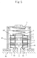
- FIG. 5 depicts the application of the oil filter not using a filter paper but using permanent magnets that replaces an inside cartridge type oil filter.
- he oil filter of FIG. 5 consists of a non-magnetic oil element case that is firmly attached to the machinery and an exchangeable disc-shaped magnetic elements.
- the disc-shaped magnetic element is applied to a paper oil filter element.
- the disc-shaped magnetic element A3 in FIG. 5 consists of disc-shaped permanent magnets 4, yokes 3, an element set bolt 80 , non-magnetic support plates 5 and nuts 8.
- the disc-shaped permanent magnets 4 have magnetic fields on their each ends.
- the yokes 3 are attached to the both sides of magnets 4 's end.
- the magnets 4 are placed parallel each other and the adjacent magnets have same magnetic field that is N pole to N pole and S pole to S pole.
- the central parts of magnets 4 are vacant.
- the element set bolt 80 is inserted to the vacant central parts of magnets 4.
- Non-magnetic support plates 5 have holes 14 which allow oil to go through.
- the plates 5 are arranged between the permanent magnets 4.
- Nuts 8 are put on the top of the element set bolt 80 .
- the oil element case 82 is fixed to engine 83.
- the disc-shaped magnetic element A3 is placed inside of the oil element case 82 along with seat packing 84 and an oil element cap 1 is tightened.
- the oil that comes into the inside of the oil filter passes through the holes 14 of the support plates 5 and then goes through the both ends of the disc-shaped permanent magnets that adjacent to the holes and goes into the central vacant part of set volt 80 and finally goes out to the inside of the engine.
- the oil flows as designed.
- the above mentioned devise is applied to an element exchangeable oil flow filter for automobiles. It emits strong magnetic field lines which repel each other and it could be take out from automobiles for cleaning so that we do not have to use a disposable paper oil filter element.
- the oil filter does not require conventional paper oil filters.
- the magnetic micro particles are surely absorbed to the disc-shaped permanent magnets while they pass between the magnets that repel each other as N pole against N pole and S pole against S pole.
- the oil filter in FIG. 5 is applied to the element exchangeable oil flow filters for automobiles, but it could be applied to not only automobiles but also motorcycles, industrial vehicles, oil pressure machinery and air machinery with the same shaped element exchangeable oil filters as the oil filter in FIG. 5.
- FIG. 6 indicates another application of the oil filter not Using a filter paper but using permanent magnets that replaces the inside cartridge type oil filter and which consists of a non-magnetic oil element case that is firmly attached to the machinery and an exchangeable disc-shaped magnetic element.
- stick-shaped permanent magnets 25 are arranged to form a circle with magnetic fields on their longer ends and a same interval between each magnet. The magnets are placed in the way so that all the same poles are outside of the circle or inside of the circle, that is; all N-poles are outside of the circle while all S-poles are inside of the circle or vice versa.
- the magnets 25 are fixed by attaching the set plates 24 to the both ends of the magnets.
- the first turbulent plate 29 and the second turbulent plate 30 are placed inside of the permanent magnets and the plates 29 and 30 have holes to make oil flow turbulent.
- the magnets 25 and the plates 29 and 30 are fixed by an outside tube 26, a top end plate 23 and a bottom end plate 27.
- This type of the oil filter without using a filter paper is called a stick-shaped magnet type element B3.
- the stick-shaped magnet type element B3 is placed inside of the oil element case 92 along with seat packing 95 .
- the oil element case 92 is attached to an engine. And then an oil element cap 21 is tightened.
- oil come into the inside of the oil filter through admission valves 90 and passes through the holes 36 of the outside tube 26 and goes through between the adjacent stick-shaped permanent magnets 25. Then it goes through the turbulent plates 29 and 30 and goes out to the inside of the engine 94. Oil flows as designed.
- the oil filter does not require conventional paper oil filters.
- the magnetic micro particles are surely absorbed to the stick-shaped permanent magnets while they pass through between the magnets which repel each other as N pole against N pole and S pole against S pole.
- the oil filter in FIG. 6 is applied to the element exchangeable oil flow filters for automobiles, but it could be applied to not only automobiles but also motorcycles, industrial vehicles, oil pressure machinery and air machinery with the same shaped element exchangeable oil filters as the oil filter in FIG. 6.
- This invention is, along with the above mentioned two particulars, to replace paper elements in the oil filter with repelling large magnets (N to N, S to S) utilizing the space that would be occupied by paper filter. This is to ensure removal of magnetic micro particles in the oil with large areas of attraction and to extend the time between cleaning of the parts. And, by placing the magnets and the repelling magnetic fields closer together, It has wider effective area, hence, extending the time in which the oil goes through the magnetic field.
- the oil filter in the diagram 6 is applied to the element exchangeable oil flow filters for automobiles but it could be applied to not only automobiles but also motorcycles, industrial vehicles: oil pressure machinery and air machinery with the same shaped element exchangeable oil filters as the oil filter in the diagram 6.
- the diagram 7 indicates how hydroxyl equivalent of the oil from Automobile 1 decreases.
- the axis of ordinates is hydroxyl equivalent(mg KOH/g) and the axis of abscissas is mileage(km).
- the hydroxyl equivalent decreases to zero at the mileage of 3670 km after the continuous drive with high speed for three days due to rapid degradation of oil caused by high temperature.
- the hydroxyl equivalent is supposed to decrease to zero at the mileage of 3000 km due to rapid degradation of the oil caused by not only high temperature but also heat as the result of friction generated by adulteration of oil.
- the oil filter not using filter papers but pemanent magnets enhances the wrapping process within an engine and it helps to decrease heat produced by friction.
- the filter also decreases adulteration of blow-by gas into oil and it prevents oil from degradation.
- the hydroxyl equivalent of oil decreases in a straight line.
- the span of oil life for the oil used with the invented oil filter is supposed to become twice longer than that for the oil used with the conventional oil filter.
- the invented oil filters keep good conditions of internal combustion engines, transmissions, reduction gears, and oil presser machinery in automobiles, ships, trains, other industrial vehicles and machinery . It lengthens life span of machinery , saves fuel cost and reduces environmental polluted gas. It make possible to use oil filter continuously for a long time and stop deforestation for producing filter papers.
Landscapes
- Engineering & Computer Science (AREA)
- Water Supply & Treatment (AREA)
- Chemical & Material Sciences (AREA)
- Chemical Kinetics & Catalysis (AREA)
- Lubrication Details And Ventilation Of Internal Combustion Engines (AREA)
- Filtration Of Liquid (AREA)
- Water Treatment By Sorption (AREA)
- Fats And Perfumes (AREA)
- Filtering Materials (AREA)
- Feeding And Controlling Fuel (AREA)
Applications Claiming Priority (4)
| Application Number | Priority Date | Filing Date | Title |
|---|---|---|---|
| JP34431495 | 1995-12-06 | ||
| JP344314/95 | 1995-12-06 | ||
| JP34431495 | 1995-12-06 | ||
| PCT/JP1996/003506 WO1997020613A1 (en) | 1995-12-06 | 1996-11-29 | Oil filter not using filter paper but using permanent magnets |
Publications (3)
| Publication Number | Publication Date |
|---|---|
| EP0873774A1 true EP0873774A1 (de) | 1998-10-28 |
| EP0873774A4 EP0873774A4 (de) | 1999-09-15 |
| EP0873774B1 EP0873774B1 (de) | 2002-10-09 |
Family
ID=18368288
Family Applications (1)
| Application Number | Title | Priority Date | Filing Date |
|---|---|---|---|
| EP96940154A Expired - Lifetime EP0873774B1 (de) | 1995-12-06 | 1996-11-29 | Ölfilter mit einem dauermagneten anstelle eines filterpapiers |
Country Status (9)
| Country | Link |
|---|---|
| EP (1) | EP0873774B1 (de) |
| JP (1) | JP3378942B2 (de) |
| KR (1) | KR100386823B1 (de) |
| CN (1) | CN1074682C (de) |
| AT (1) | ATE225678T1 (de) |
| AU (1) | AU7710796A (de) |
| DE (1) | DE69624261T2 (de) |
| TW (1) | TW359320U (de) |
| WO (1) | WO1997020613A1 (de) |
Cited By (7)
| Publication number | Priority date | Publication date | Assignee | Title |
|---|---|---|---|---|
| WO2001078863A1 (en) * | 2000-04-19 | 2001-10-25 | Eclipse Magnetics Limited | Magnetic filter |
| EP2108454A1 (de) * | 2008-04-08 | 2009-10-14 | BP Oil International Limited | Verbesserungen an oder im Zusammenhang mit Filtern |
| US7604748B2 (en) | 2005-10-20 | 2009-10-20 | Eclipse Magnetics Limited | Magnetic filter |
| WO2013175195A1 (en) * | 2012-05-21 | 2013-11-28 | Adey Holdings (2008) Limited | Separator device for a heating system |
| US8905244B2 (en) | 2010-09-03 | 2014-12-09 | Komatsu Ltd. | Oil filter and valve device |
| US9149740B2 (en) | 2010-12-01 | 2015-10-06 | Adey Holdings (2008) Limited | Water and dirt separator |
| US9463471B2 (en) | 2010-12-01 | 2016-10-11 | Adey Holdings (2008) Limited | Water and dirt separator |
Families Citing this family (12)
| Publication number | Priority date | Publication date | Assignee | Title |
|---|---|---|---|---|
| US6210572B1 (en) | 1999-10-18 | 2001-04-03 | Technology Commercialization Corp. | Filter and method for purifying liquids containing magnetic particles |
| US7662282B2 (en) * | 2006-12-26 | 2010-02-16 | Iowa State University Research Foundation, Inc. | Permanent magnet array iron filter |
| BRPI0818247B1 (pt) * | 2007-10-08 | 2018-12-18 | t hale John | "aparelho para tratar magneticamente um fluido, sistema de bombeamento por haste de sucção e método para expor um fluido a um campo magnético". |
| CN102319704B (zh) * | 2011-08-30 | 2013-03-27 | 中国电子科技集团公司第四十九研究所 | 一种利用磁性感应器捕捉金属屑的装置 |
| CN102537640B (zh) * | 2012-02-03 | 2014-06-25 | 吉首大学 | 一种高效组合式油过滤器 |
| KR200470150Y1 (ko) * | 2012-03-14 | 2013-11-29 | 대우조선해양 주식회사 | 오일 여과장치 |
| GB2491246B (en) * | 2012-05-21 | 2013-05-15 | Adey Holdings 2008 Ltd | Separator device |
| KR102198228B1 (ko) * | 2012-11-02 | 2021-01-04 | 아데이 홀딩스(2008) 리미티드 | 자력 선별기 |
| AT513793A1 (de) * | 2012-12-21 | 2014-07-15 | Frauenschuh Josef | Anordnung zum Sammeln von magnetisierbaren Metallteilen in einem Fluid an einer Magnetvorrichtung |
| WO2018101182A1 (ja) * | 2016-11-30 | 2018-06-07 | 株式会社ターゲンテックス | 永久磁石の反発しあうバランスの良い磁力線を有効に用いたオイルフィルターエレメント |
| CN108119203B (zh) * | 2018-01-02 | 2020-08-14 | 沈阳皓宇中科科技有限公司 | 一种节能减污适用于可溶性净油剂的组件及净油器 |
| CN112717534B (zh) * | 2021-01-08 | 2024-06-14 | 临武县舜水环境治理有限公司 | 磁性材料过滤回收装置 |
Family Cites Families (12)
| Publication number | Priority date | Publication date | Assignee | Title |
|---|---|---|---|---|
| US3900400A (en) * | 1974-04-29 | 1975-08-19 | Caterpillar Tractor Co | Dual filter arrangement |
| JPS58143891A (ja) * | 1982-02-17 | 1983-08-26 | Koji Nakamura | 液体に含有する磁性粉体の除去とスケ−ルの付着予防及除去装置 |
| JPS6295111A (ja) * | 1985-10-18 | 1987-05-01 | Honda Motor Co Ltd | オイルフイルタ装置 |
| US4663034A (en) * | 1985-11-07 | 1987-05-05 | Aldo Morelli | Hydraulic filter system for excavation equipment |
| JPS62164957A (ja) * | 1986-01-16 | 1987-07-21 | 株式会社ナカ技術研究所 | 点検口における外枠の取付構造 |
| US4705626A (en) * | 1986-03-19 | 1987-11-10 | Aldo Morelli | Magnetic oil filter module |
| NZ218331A (en) * | 1986-11-19 | 1990-10-26 | Debug Filters Ltd | Control of protistal growth in hydrocarbon fuel by magnetic field |
| US5228990A (en) * | 1992-04-01 | 1993-07-20 | Jean Chiang | Oil filter |
| JP2516528B2 (ja) * | 1992-05-27 | 1996-07-24 | 幸司 中村 | 永久磁石による潤滑油の劣化防止装置 |
| JP3180277B2 (ja) * | 1992-08-07 | 2001-06-25 | 本田技研工業株式会社 | オイルフィルタ |
| JPH09984A (ja) * | 1995-06-19 | 1997-01-07 | Hitachi Koki Co Ltd | 遠心分離機用温度制御装置 |
| WO1997001702A1 (en) * | 1995-06-28 | 1997-01-16 | Rem 95 Di Deiana M.L. & C. S.A.S. | A device for conditioning fuel |
-
1996
- 1996-11-29 JP JP52114997A patent/JP3378942B2/ja not_active Expired - Lifetime
- 1996-11-29 AU AU77107/96A patent/AU7710796A/en not_active Abandoned
- 1996-11-29 CN CN96199116A patent/CN1074682C/zh not_active Expired - Lifetime
- 1996-11-29 WO PCT/JP1996/003506 patent/WO1997020613A1/ja not_active Ceased
- 1996-11-29 KR KR10-1998-0704003A patent/KR100386823B1/ko not_active Expired - Fee Related
- 1996-11-29 EP EP96940154A patent/EP0873774B1/de not_active Expired - Lifetime
- 1996-11-29 AT AT96940154T patent/ATE225678T1/de not_active IP Right Cessation
- 1996-11-29 DE DE69624261T patent/DE69624261T2/de not_active Expired - Lifetime
- 1996-12-02 TW TW087216557U patent/TW359320U/zh unknown
Cited By (12)
| Publication number | Priority date | Publication date | Assignee | Title |
|---|---|---|---|---|
| WO2001078863A1 (en) * | 2000-04-19 | 2001-10-25 | Eclipse Magnetics Limited | Magnetic filter |
| US7604748B2 (en) | 2005-10-20 | 2009-10-20 | Eclipse Magnetics Limited | Magnetic filter |
| EP2108454A1 (de) * | 2008-04-08 | 2009-10-14 | BP Oil International Limited | Verbesserungen an oder im Zusammenhang mit Filtern |
| US8905244B2 (en) | 2010-09-03 | 2014-12-09 | Komatsu Ltd. | Oil filter and valve device |
| US9149740B2 (en) | 2010-12-01 | 2015-10-06 | Adey Holdings (2008) Limited | Water and dirt separator |
| US9463471B2 (en) | 2010-12-01 | 2016-10-11 | Adey Holdings (2008) Limited | Water and dirt separator |
| WO2013175195A1 (en) * | 2012-05-21 | 2013-11-28 | Adey Holdings (2008) Limited | Separator device for a heating system |
| US20150096928A1 (en) * | 2012-05-21 | 2015-04-09 | Adey Holdings Limited | Separator Device for a Heating System |
| US9162908B2 (en) * | 2012-05-21 | 2015-10-20 | Adey Holdings (2008) Limited | Separator device for a heating system |
| RU2643971C2 (ru) * | 2012-05-21 | 2018-02-06 | Эйди Хоулдингс (2008) Лимитед | Сепараторное устройство |
| RU2643971C9 (ru) * | 2012-05-21 | 2018-03-15 | Эйди Хоулдингс (2008) Лимитед | Сепараторное устройство |
| GB2502278B (en) * | 2012-05-21 | 2020-01-01 | Adey Holdings 2008 Ltd | Separator device |
Also Published As
| Publication number | Publication date |
|---|---|
| KR100386823B1 (ko) | 2003-08-27 |
| DE69624261D1 (de) | 2002-11-14 |
| TW359320U (en) | 1999-05-21 |
| EP0873774A4 (de) | 1999-09-15 |
| DE69624261T2 (de) | 2003-07-10 |
| CN1205649A (zh) | 1999-01-20 |
| KR19990071725A (ko) | 1999-09-27 |
| AU7710796A (en) | 1997-06-27 |
| ATE225678T1 (de) | 2002-10-15 |
| CN1074682C (zh) | 2001-11-14 |
| JP3378942B2 (ja) | 2003-02-17 |
| WO1997020613A1 (en) | 1997-06-12 |
| EP0873774B1 (de) | 2002-10-09 |
Similar Documents
| Publication | Publication Date | Title |
|---|---|---|
| EP0873774B1 (de) | Ölfilter mit einem dauermagneten anstelle eines filterpapiers | |
| JPWO1997020613A1 (ja) | 濾紙を使用しない永久磁石によるオイルフィルター | |
| US6270667B1 (en) | Oil filter not using filter paper but using permanent magnets | |
| US3800914A (en) | Magnetic filter for lubricants | |
| US4450075A (en) | Magnetic oil filter insert | |
| US6210572B1 (en) | Filter and method for purifying liquids containing magnetic particles | |
| Jain et al. | Experimental investigation of magnetic fuel conditioner (MFC) in IC engine | |
| CN102330625A (zh) | 汽车机油和燃油净化及燃油预热组件 | |
| Glavaš et al. | Essential preventive automobile maintenance during a pandemic | |
| US20030173301A1 (en) | Fibrous filter assembly and method | |
| Van Donkelaar | Environmental effects of crankcase-and mixed-lubrication | |
| US5949317A (en) | Magnetic drain plug | |
| CN112780758B (zh) | 一种减速器内润滑油金属微粒过滤装置 | |
| CN202132084U (zh) | 旋装可拆双重深层过滤机油燃油滤清器 | |
| US4613435A (en) | Magnetic oil filter | |
| GB2361441A (en) | Magnetic filter in association with a porous filter | |
| JP2516528B2 (ja) | 永久磁石による潤滑油の劣化防止装置 | |
| JPS58143891A (ja) | 液体に含有する磁性粉体の除去とスケ−ルの付着予防及除去装置 | |
| Jiang et al. | Abrasive wear of locomotive diesel engines and contaminant control | |
| CN202100364U (zh) | 旋装长纤维磁性双重深层过滤机油燃油滤清器 | |
| JPH04326908A (ja) | エンジンの潤滑オイルに含有される鉄粉除去装置 | |
| JPS627789A (ja) | 燃料の磁化促進装置 | |
| Kołodziejski et al. | Test verification of the condition of hydraulic oil of construction machines following the guidelines of ISO 4406 and NAS 1638 | |
| WO2018101182A1 (ja) | 永久磁石の反発しあうバランスの良い磁力線を有効に用いたオイルフィルターエレメント | |
| CN2376545Y (zh) | 节能净化装置 |
Legal Events
| Date | Code | Title | Description |
|---|---|---|---|
| PUAI | Public reference made under article 153(3) epc to a published international application that has entered the european phase |
Free format text: ORIGINAL CODE: 0009012 |
|
| 17P | Request for examination filed |
Effective date: 19980602 |
|
| AK | Designated contracting states |
Kind code of ref document: A1 Designated state(s): AT BE CH DE DK ES FI FR GB GR IE IT LI LU MC NL PT SE |
|
| A4 | Supplementary search report drawn up and despatched |
Effective date: 19990730 |
|
| AK | Designated contracting states |
Kind code of ref document: A4 Designated state(s): AT BE CH DE DK ES FI FR GB GR IE IT LI LU MC NL PT SE |
|
| 17Q | First examination report despatched |
Effective date: 20010308 |
|
| GRAG | Despatch of communication of intention to grant |
Free format text: ORIGINAL CODE: EPIDOS AGRA |
|
| GRAG | Despatch of communication of intention to grant |
Free format text: ORIGINAL CODE: EPIDOS AGRA |
|
| GRAH | Despatch of communication of intention to grant a patent |
Free format text: ORIGINAL CODE: EPIDOS IGRA |
|
| GRAH | Despatch of communication of intention to grant a patent |
Free format text: ORIGINAL CODE: EPIDOS IGRA |
|
| GRAA | (expected) grant |
Free format text: ORIGINAL CODE: 0009210 |
|
| AK | Designated contracting states |
Kind code of ref document: B1 Designated state(s): AT BE CH DE DK ES FI FR GB GR IE IT LI LU MC NL PT SE |
|
| PG25 | Lapsed in a contracting state [announced via postgrant information from national office to epo] |
Ref country code: NL Free format text: LAPSE BECAUSE OF FAILURE TO SUBMIT A TRANSLATION OF THE DESCRIPTION OR TO PAY THE FEE WITHIN THE PRESCRIBED TIME-LIMIT Effective date: 20021009 Ref country code: LI Free format text: LAPSE BECAUSE OF FAILURE TO SUBMIT A TRANSLATION OF THE DESCRIPTION OR TO PAY THE FEE WITHIN THE PRESCRIBED TIME-LIMIT Effective date: 20021009 Ref country code: IT Free format text: LAPSE BECAUSE OF FAILURE TO SUBMIT A TRANSLATION OF THE DESCRIPTION OR TO PAY THE FEE WITHIN THE PRESCRIBED TIME-LIMIT;WARNING: LAPSES OF ITALIAN PATENTS WITH EFFECTIVE DATE BEFORE 2007 MAY HAVE OCCURRED AT ANY TIME BEFORE 2007. THE CORRECT EFFECTIVE DATE MAY BE DIFFERENT FROM THE ONE RECORDED. Effective date: 20021009 Ref country code: GR Free format text: LAPSE BECAUSE OF FAILURE TO SUBMIT A TRANSLATION OF THE DESCRIPTION OR TO PAY THE FEE WITHIN THE PRESCRIBED TIME-LIMIT Effective date: 20021009 Ref country code: FI Free format text: LAPSE BECAUSE OF FAILURE TO SUBMIT A TRANSLATION OF THE DESCRIPTION OR TO PAY THE FEE WITHIN THE PRESCRIBED TIME-LIMIT Effective date: 20021009 Ref country code: CH Free format text: LAPSE BECAUSE OF FAILURE TO SUBMIT A TRANSLATION OF THE DESCRIPTION OR TO PAY THE FEE WITHIN THE PRESCRIBED TIME-LIMIT Effective date: 20021009 Ref country code: BE Free format text: LAPSE BECAUSE OF FAILURE TO SUBMIT A TRANSLATION OF THE DESCRIPTION OR TO PAY THE FEE WITHIN THE PRESCRIBED TIME-LIMIT Effective date: 20021009 Ref country code: AT Free format text: LAPSE BECAUSE OF FAILURE TO SUBMIT A TRANSLATION OF THE DESCRIPTION OR TO PAY THE FEE WITHIN THE PRESCRIBED TIME-LIMIT Effective date: 20021009 |
|
| REF | Corresponds to: |
Ref document number: 225678 Country of ref document: AT Date of ref document: 20021015 Kind code of ref document: T |
|
| REG | Reference to a national code |
Ref country code: GB Ref legal event code: FG4D |
|
| REG | Reference to a national code |
Ref country code: CH Ref legal event code: EP |
|
| REG | Reference to a national code |
Ref country code: IE Ref legal event code: FG4D |
|
| REF | Corresponds to: |
Ref document number: 69624261 Country of ref document: DE Date of ref document: 20021114 |
|
| PG25 | Lapsed in a contracting state [announced via postgrant information from national office to epo] |
Ref country code: LU Free format text: LAPSE BECAUSE OF NON-PAYMENT OF DUE FEES Effective date: 20021129 Ref country code: IE Free format text: LAPSE BECAUSE OF NON-PAYMENT OF DUE FEES Effective date: 20021129 |
|
| PG25 | Lapsed in a contracting state [announced via postgrant information from national office to epo] |
Ref country code: SE Free format text: LAPSE BECAUSE OF FAILURE TO SUBMIT A TRANSLATION OF THE DESCRIPTION OR TO PAY THE FEE WITHIN THE PRESCRIBED TIME-LIMIT Effective date: 20030109 Ref country code: PT Free format text: LAPSE BECAUSE OF FAILURE TO SUBMIT A TRANSLATION OF THE DESCRIPTION OR TO PAY THE FEE WITHIN THE PRESCRIBED TIME-LIMIT Effective date: 20030109 Ref country code: DK Free format text: LAPSE BECAUSE OF FAILURE TO SUBMIT A TRANSLATION OF THE DESCRIPTION OR TO PAY THE FEE WITHIN THE PRESCRIBED TIME-LIMIT Effective date: 20030109 |
|
| NLV1 | Nl: lapsed or annulled due to failure to fulfill the requirements of art. 29p and 29m of the patents act | ||
| REG | Reference to a national code |
Ref country code: CH Ref legal event code: PL |
|
| ET | Fr: translation filed | ||
| PG25 | Lapsed in a contracting state [announced via postgrant information from national office to epo] |
Ref country code: ES Free format text: LAPSE BECAUSE OF FAILURE TO SUBMIT A TRANSLATION OF THE DESCRIPTION OR TO PAY THE FEE WITHIN THE PRESCRIBED TIME-LIMIT Effective date: 20030429 |
|
| PG25 | Lapsed in a contracting state [announced via postgrant information from national office to epo] |
Ref country code: MC Free format text: LAPSE BECAUSE OF NON-PAYMENT OF DUE FEES Effective date: 20030601 |
|
| PLBE | No opposition filed within time limit |
Free format text: ORIGINAL CODE: 0009261 |
|
| STAA | Information on the status of an ep patent application or granted ep patent |
Free format text: STATUS: NO OPPOSITION FILED WITHIN TIME LIMIT |
|
| REG | Reference to a national code |
Ref country code: IE Ref legal event code: MM4A |
|
| 26N | No opposition filed |
Effective date: 20030710 |
|
| PGFP | Annual fee paid to national office [announced via postgrant information from national office to epo] |
Ref country code: FR Payment date: 20131111 Year of fee payment: 18 Ref country code: GB Payment date: 20131112 Year of fee payment: 18 |
|
| PGFP | Annual fee paid to national office [announced via postgrant information from national office to epo] |
Ref country code: DE Payment date: 20141120 Year of fee payment: 19 |
|
| GBPC | Gb: european patent ceased through non-payment of renewal fee |
Effective date: 20141129 |
|
| REG | Reference to a national code |
Ref country code: FR Ref legal event code: ST Effective date: 20150731 |
|
| PG25 | Lapsed in a contracting state [announced via postgrant information from national office to epo] |
Ref country code: GB Free format text: LAPSE BECAUSE OF NON-PAYMENT OF DUE FEES Effective date: 20141129 |
|
| PG25 | Lapsed in a contracting state [announced via postgrant information from national office to epo] |
Ref country code: FR Free format text: LAPSE BECAUSE OF NON-PAYMENT OF DUE FEES Effective date: 20141201 |
|
| REG | Reference to a national code |
Ref country code: DE Ref legal event code: R119 Ref document number: 69624261 Country of ref document: DE |
|
| PG25 | Lapsed in a contracting state [announced via postgrant information from national office to epo] |
Ref country code: DE Free format text: LAPSE BECAUSE OF NON-PAYMENT OF DUE FEES Effective date: 20160601 |