EP0873885A2 - Luftreifen - Google Patents
Luftreifen Download PDFInfo
- Publication number
- EP0873885A2 EP0873885A2 EP98107124A EP98107124A EP0873885A2 EP 0873885 A2 EP0873885 A2 EP 0873885A2 EP 98107124 A EP98107124 A EP 98107124A EP 98107124 A EP98107124 A EP 98107124A EP 0873885 A2 EP0873885 A2 EP 0873885A2
- Authority
- EP
- European Patent Office
- Prior art keywords
- block row
- block
- tire
- leading edge
- pneumatic tire
- Prior art date
- Legal status (The legal status is an assumption and is not a legal conclusion. Google has not performed a legal analysis and makes no representation as to the accuracy of the status listed.)
- Granted
Links
- 230000000052 comparative effect Effects 0.000 description 14
- 238000000034 method Methods 0.000 description 6
- 230000000694 effects Effects 0.000 description 3
- 238000002474 experimental method Methods 0.000 description 2
- 238000007796 conventional method Methods 0.000 description 1
- 230000003247 decreasing effect Effects 0.000 description 1
- 230000006866 deterioration Effects 0.000 description 1
- 238000011156 evaluation Methods 0.000 description 1
- 238000005259 measurement Methods 0.000 description 1
- XLYOFNOQVPJJNP-UHFFFAOYSA-N water Substances O XLYOFNOQVPJJNP-UHFFFAOYSA-N 0.000 description 1
Images






Classifications
-
- B—PERFORMING OPERATIONS; TRANSPORTING
- B60—VEHICLES IN GENERAL
- B60C—VEHICLE TYRES; TYRE INFLATION; TYRE CHANGING; CONNECTING VALVES TO INFLATABLE ELASTIC BODIES IN GENERAL; DEVICES OR ARRANGEMENTS RELATED TO TYRES
- B60C11/00—Tyre tread bands; Tread patterns; Anti-skid inserts
- B60C11/03—Tread patterns
- B60C11/0318—Tread patterns irregular patterns with particular pitch sequence
-
- B—PERFORMING OPERATIONS; TRANSPORTING
- B60—VEHICLES IN GENERAL
- B60C—VEHICLE TYRES; TYRE INFLATION; TYRE CHANGING; CONNECTING VALVES TO INFLATABLE ELASTIC BODIES IN GENERAL; DEVICES OR ARRANGEMENTS RELATED TO TYRES
- B60C11/00—Tyre tread bands; Tread patterns; Anti-skid inserts
-
- B—PERFORMING OPERATIONS; TRANSPORTING
- B60—VEHICLES IN GENERAL
- B60C—VEHICLE TYRES; TYRE INFLATION; TYRE CHANGING; CONNECTING VALVES TO INFLATABLE ELASTIC BODIES IN GENERAL; DEVICES OR ARRANGEMENTS RELATED TO TYRES
- B60C11/00—Tyre tread bands; Tread patterns; Anti-skid inserts
- B60C11/03—Tread patterns
- B60C11/0327—Tread patterns characterised by special properties of the tread pattern
- B60C11/0332—Tread patterns characterised by special properties of the tread pattern by the footprint-ground contacting area of the tyre tread
-
- B—PERFORMING OPERATIONS; TRANSPORTING
- B60—VEHICLES IN GENERAL
- B60C—VEHICLE TYRES; TYRE INFLATION; TYRE CHANGING; CONNECTING VALVES TO INFLATABLE ELASTIC BODIES IN GENERAL; DEVICES OR ARRANGEMENTS RELATED TO TYRES
- B60C11/00—Tyre tread bands; Tread patterns; Anti-skid inserts
- B60C11/03—Tread patterns
- B60C11/11—Tread patterns in which the raised area of the pattern consists only of isolated elements, e.g. blocks
-
- Y—GENERAL TAGGING OF NEW TECHNOLOGICAL DEVELOPMENTS; GENERAL TAGGING OF CROSS-SECTIONAL TECHNOLOGIES SPANNING OVER SEVERAL SECTIONS OF THE IPC; TECHNICAL SUBJECTS COVERED BY FORMER USPC CROSS-REFERENCE ART COLLECTIONS [XRACs] AND DIGESTS
- Y10—TECHNICAL SUBJECTS COVERED BY FORMER USPC
- Y10S—TECHNICAL SUBJECTS COVERED BY FORMER USPC CROSS-REFERENCE ART COLLECTIONS [XRACs] AND DIGESTS
- Y10S152/00—Resilient tires and wheels
- Y10S152/902—Non-directional tread pattern having no circumferential rib and having blocks defined by circumferential grooves and transverse grooves
Definitions
- the present invention relates to a pneumatic tire, and more particularly, to a pneumatic tire in which pattern noise is reduced while other properties (in particular, performance on wet road surfaces) are maintained.
- Lug grooves which endow a pneumatic tire with performance on wet road surfaces and resistance to hydroplaning in particular, are indispensable to pneumatic tires.
- pitch noise impact noise
- the negative ratio there is a correlation among the negative ratio, the sound level, and the performance on wet road surfaces. If the negative ratio is reduced, the sound level improves, but the performance on wet road surfaces deteriorates. If the negative ratio is increased, the performance on wet road surfaces improves, but the sound level deteriorates.
- an object of the present invention is to provide a pneumatic tire in which pattern noise can be reduced without a deterioration in the performance on wet road surfaces.
- impact noise is generated when a tire 100 rotates and a block 102 contacts a road surface 104.
- this impact noise will be called “pitch noise”, and the waveform thereof is illustrated in Fig. 11.
- the angle of the edge portion of the block is an important factor. Therefore, the present inventors studied the angle of the block edge portion.
- the magnitude of the pitch noise is determined by the angle formed by the tire leading edge side contour line of the ground-contact configuration and the side surface of the block leading edge side.
- the pitch noise is lowest.
- the ground-contact angle ⁇ is the angle formed by the tire circumferential direction and a tangent line SL which passes through a point tangent to the block 102 leading edge (the end portion which first contacts the ground).
- the angular difference between ⁇ and ⁇ is important to the reduction of pitch noise.
- the angles at the respective portions are set as illustrated in Figs. 14A and 14B. Namely, with respect to a block 102R at the right side of a tire equatorial plane CL, the angles are defined in the clockwise direction.
- the angle at the block leading edge is ⁇ 1
- the ground-contact angle formed by the tire circumferential direction and the tire leading edge side contour line 106 of the ground-contact configuration is ⁇ 1.
- the angles are defined in the counterclockwise direction.
- the angle at the block leading edge is ⁇ 2
- the ground-contact angle formed by the tire circumferential direction and the tire leading edge side contour line 106 of the ground-contact configuration is ⁇ 2.
- the positional relationships among the tire leading edge side contour line 106, the side surface 102A of the leading edge side of the block 102R at the right side of the tire equatorial plane CL, and the side surface 102A of the leading edge side of the block 102L at the left side of the tire equatorial plane CL, are as follows.
- the angular difference between the ground-contact angle ⁇ and the angle ⁇ of the block leading edge is important to the pitch noise.
- the relationship between the angles and the magnitude of the pitch noise is as shown in Fig. 15.
- Fig. 15 illustrates that pitch noise of a magnitude P1 is generated from the block 102 at the right side of the tire equatorial plane CL, and pitch noise of a magnitude P2 is generated from the block 102 at the left side of the tire equatorial plane CL. ( ⁇ 2 ⁇ 1, and therefore, the magnitudes of the pitch noise are P2>P1.)
- phase difference for respective pitch noises generated from block rows of blocks (generally, pairs of left and right blocks with respect to an axis extending along the tire circumferential direction (e.g., the tire equatorial plane CL)
- the sounds can cancel each other out.
- the necessary extent of the phase difference differs in accordance with the configurations or the like of respective tires, and is determined for each tire.
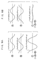
- Figs. 16A and 16B two sounds (A ⁇ and B ⁇ ) are completely reverse phases.
- the magnitude of the amplitude Pa and the magnitude of the amplitude Pb are equal, the magnitude of the combined sound is a minimum (Fig. 16B).
- the magnitude of the combined sound is not zero, and a sound having a magnitude of an amplitude
- the angles of inclination of the lug grooves are equal, i.e., the side surface 102A of the leading edge side of the block 102L at the left side of the tire equatorial plane CL and the side surface 102A of the leading edge side of the block 102R at the right side of the tire equatorial plane CL are substantially parallel (i.e., ⁇ 1 ⁇ ⁇ 2).
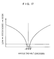
- the angular difference ⁇ 1 of the block 102R at the right side of the tire equatorial plane CL and the angular difference ⁇ 2 of the block 102L at the left side of the tire equatorial plane CL are not the same.
- the magnitude of the pitch noise generated if ⁇ 2 is fixed and ⁇ 1 is made small is P2
- the magnitude of the pitch noise generated if ⁇ 1 is fixed and ⁇ 2 is made large P1.
- both the method of fixing ⁇ 2 and making ⁇ 1 small and the method of fixing ⁇ 1 and making ⁇ 2 large are the same.
- One aspect of the present invention is a pneumatic tire comprising: a first block row in which a plurality of blocks projecting from an outer circumference of the pneumatic tire are disposed along a tire circumferential direction; and a second block row in which a plurality of blocks projecting from the outer circumference of the pneumatic tire are disposed along the tire circumferential direction, the second block row being parallel to the first block row, wherein a side surface of a leading edge side end portion of each block of the first block row and the second block row is inclined with respect to a tire transverse direction such that an angle, which is formed by the side surface of the leading edge side end portion of each block of the first block row and a tire leading edge side contour line of a ground-contact configuration, and an angle, which is formed by the side surface of the leading edge side end portion of each block of the second block row and the tire leading edge side contour line of the ground-contact configuration, are substantially equal. Therefore, the pitch noise generated at the time of step-in at the blocks of the first block row is substantially the same level
- the pitch noises of substantially the same level will interfere with one another and cancel out one another, and the pattern noise of the tire can be reduced.
- Fig. 1A is a plan view of a tread of a pneumatic tire relating to a first embodiment of the present invention, as seen from an exterior of the pneumatic tire.
- Fig. 1B is a cross-sectional view taken along line 1B-1B of Fig. 1A (and illustrating only the contour of the cross-section and not the internal structure).
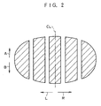
- Fig. 2 illustrates a ground-contact configuration of the pneumatic tire relating to the first embodiment.
- Fig. 3A is a view for explaining a relationship of angles of the ground-contact configuration and second blocks (wherein, for convenience of explanation, left and right second blocks are shown in a state in which there is no offset in the tire circumferential direction).
- Fig. 3B is a view for explaining a relationship of angles of the ground-contact configuration and shoulder blocks (wherein, in the same way as in Fig. 3A, left and right shoulder blocks are shown in a state in which there is no offset in the tire circumferential direction).
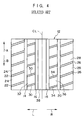
- Fig. 4 is a plan view of a tread of a pneumatic tire relating to a conventional example.
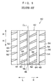
- Fig. 5 is a plan view of a tread of a pneumatic tire relating to a comparative example.
- Fig. 6 is a plan view of a tread of a pneumatic tire relating to a second embodiment of the present invention.
- Fig. 7 illustrates a ground-contact configuration of the pneumatic tire relating to the second embodiment.
- Fig. 8 is a plan view of a tread of a pneumatic tire relating to a conventional example.
- Fig. 9 is a plan view of a tread of a pneumatic tire relating to a comparative example.
- Fig. 10 is a view for explaining a pitch noise generating mechanism.
- Fig. 11 illustrates an example of measurement of pitch noise.
- Fig. 12 is a view for explaining a block leading edge angle and a ground-contact angle.
- Fig. 13 is a graph illustrating the relationship between a block leading edge angle, a ground-contact angle, and pitch noise.
- Figs. 14A and 14B are views for explaining ground-contact angles and angles of leading edges of two blocks at either side of a tire equatorial plane.
- Fig. 15 is a graph illustrating the relationship between an angle and pitch noise.
- Figs. 16A and 16B are views for explaining a method of reducing pitch noise.
- Fig. 17 is a graph illustrating the relationship between ⁇ 1- ⁇ 2 and pitch noise.
- circumferential direction grooves 14, 16, 18, 20 which extend along the tire circumferential direction (the direction of arrow A and the direction of arrow B) are formed in that order from the tire transverse direction left side (the side in the direction of arrow L) toward the transverse direction right side (the side in the direction of arrow R).
- shoulder blocks 24, which are defined by lug grooves 22 which are parallel to the tire transverse direction, are provided at the arrow L direction side of the circumferential direction groove 14.
- Shoulder blocks 28, which are defined by lug grooves 26 which are parallel to the tire transverse direction, are provided at the arrow R direction side of the circumferential direction groove 20.
- Second blocks 32 which are defined by lug grooves 30 which are inclined upwardly to the right with respect to the tire transverse direction, are formed between the circumferential direction groove 14 and the circumferential direction groove 16.
- Second blocks 36 which are defined by lug grooves 34 which are inclined upwardly to the right with respect to the tire transverse direction, are formed between the circumferential direction groove 18 and the circumferential direction groove 20.
- a rib 38 which is continuous along the tire circumferential direction, is formed between the circumferential direction groove 16 and the circumferential direction groove 18.
- the ground-contact configuration of the pneumatic tire 10 is substantially oval as illustrated in Fig. 2.
- the vertical lines in Fig. 2 are the traces of the circumferential direction grooves.
- the traces of the lug grooves are omitted from the figure.
- an Embodiment 1 tire to which the present invention was applied a Conventional Example 1 tire, and a Comparative Example 1 tire were prepared, and the pattern noises and performances on wet road surfaces thereof were compared.
- the pattern of the Conventional Example 1 tire was as shown in Fig. 4, and the pattern of the Comparative Example 1 tire was as shown in Fig. 5.
- the angles of the respective regions and the like were as shown in above Table 1.
- Each of the tires used in the experiments was the same size (PSR 225/50R16).
- the ground-contact configuration at the time the tire was mounted to a 7JJ rim, inflated to an internal pressure of 230 kPa, and subjected to a load of 400 kg was used.
- Each of the tires had the same negative ratio.
- the pattern noise (as measured by instrument) was the measured value with a sound meter set within the driver's seat in a vicinity of the position of a driver's ear at the time the vehicle was allowed to coast on a straight, flat road after reaching a speed of 55 km/h.
- the pattern noise (as evaluated by feeling) was the results of evaluation by the senses of a vehicle occupant under the same conditions as described above. These results were expressed as indices with the Conventional Example 1 tire having a value of 100, and the higher the value, the better the feeling (i.e., the less unpleasant).
- the performance on wet road surfaces was evaluated by the time required for a vehicle to pass over a 90 m section of a wet road surface with a depth of water of 5 mm, while zigzagging through 5 pylons.
- the results were expressed as indices with the time of the Conventional Example 1 tire being an index of 100. The higher the value, the shorter the time, and the better the performance on wet road surfaces.
- the Embodiment 1 tire to which the present invention was applied had a pattern noise which was 1.2 dB lower than the Conventional Example 1 tire, and the Comparative Example 1 tire had a pattern noise which was 0.5 dB higher than the Conventional Example 1 tire. Further, the pattern noise of the Embodiment 1 tire also exhibited good results when evaluated by the feeling of the vehicle occupant.
- the pattern noise of the Embodiment 1 tire to which the present invention was applied was less than that of the Conventional Example 1 tire and the Comparative Example 1 tire.
- Embodiment 1 tire, the Conventional Example 1 tire, and the Comparative Example 1 tire were all the same.
- the angles are set in the same way, and there is no directionality with respect to the mounting of the tire. Therefore, the groove widths of the lug grooves 30, 34 are not parallel to each other.
- circumferential direction grooves 44, 46, 48 which extend along the tire circumferential direction (the direction of arrow A and the direction of arrow B), are formed in that order from the tire transverse direction left side (the side in the direction of arrow L) toward the tire transverse direction right side (the side in the direction of arrow R).
- shoulder blocks 52 defined by lug grooves 50 are disposed at the arrow L direction side of the circumferential direction groove 44.
- Shoulder blocks 56 defined by lug grooves 54 are disposed at the arrow R direction side of the circumferential direction groove 48.
- Second blocks 60 defined by lug grooves 58 are formed between the circumferential direction groove 44 and the circumferential direction groove 46.
- Second blocks 64 defined by lug grooves 62 are formed between the circumferential direction groove 46 and the circumferential direction groove 48.
- the ground-contact configuration of the pneumatic tire 40 is a substantial rectangle having slightly rounded corners as illustrated in Fig. 7.
- the vertical lines in Fig. 7 are the traces of the circumferential direction grooves.
- the traces of the lug grooves are omitted from the figure.
- the pneumatic tire 40 of Embodiment 2 a pneumatic tire 66 of Conventional Example 2 having the pattern illustrated in Fig. 8, and a pneumatic tire 68 of Comparative Example 2 having the pattern illustrated in Fig. 9 were manufactured and were tested in the same way as in the first embodiment.
- the pattern noise of the Embodiment 2 tire to which the present invention was applied was less than that of the Conventional Example 2 tire and the Comparative Example 2 tire.
Landscapes
- Engineering & Computer Science (AREA)
- Mechanical Engineering (AREA)
- Tires In General (AREA)
Applications Claiming Priority (6)
| Application Number | Priority Date | Filing Date | Title |
|---|---|---|---|
| JP10623597 | 1997-04-23 | ||
| JP10623597 | 1997-04-23 | ||
| JP106235/97 | 1997-04-23 | ||
| JP1409098 | 1998-01-27 | ||
| JP14090/98 | 1998-01-27 | ||
| JP01409098A JP3983877B2 (ja) | 1997-04-23 | 1998-01-27 | 空気入りタイヤ |
Publications (3)
| Publication Number | Publication Date |
|---|---|
| EP0873885A2 true EP0873885A2 (de) | 1998-10-28 |
| EP0873885A3 EP0873885A3 (de) | 2000-11-15 |
| EP0873885B1 EP0873885B1 (de) | 2003-08-06 |
Family
ID=26349987
Family Applications (1)
| Application Number | Title | Priority Date | Filing Date |
|---|---|---|---|
| EP98107124A Expired - Lifetime EP0873885B1 (de) | 1997-04-23 | 1998-04-20 | Luftreifen |
Country Status (5)
| Country | Link |
|---|---|
| US (1) | US6688356B1 (de) |
| EP (1) | EP0873885B1 (de) |
| JP (1) | JP3983877B2 (de) |
| DE (1) | DE69816897T2 (de) |
| ES (1) | ES2205306T3 (de) |
Families Citing this family (7)
| Publication number | Priority date | Publication date | Assignee | Title |
|---|---|---|---|---|
| JP4641333B2 (ja) * | 2000-07-06 | 2011-03-02 | 株式会社ブリヂストン | 空気入りタイヤ |
| JP2006347227A (ja) * | 2005-06-13 | 2006-12-28 | Toyo Tire & Rubber Co Ltd | 空気入りタイヤ |
| JP5577611B2 (ja) * | 2009-03-17 | 2014-08-27 | 横浜ゴム株式会社 | 空気入りタイヤ |
| JP5879676B2 (ja) * | 2010-06-30 | 2016-03-08 | 横浜ゴム株式会社 | 空気入りタイヤ |
| JP2014097799A (ja) * | 2014-02-28 | 2014-05-29 | Yokohama Rubber Co Ltd:The | 空気入りタイヤ |
| JP7332453B2 (ja) * | 2019-12-05 | 2023-08-23 | 株式会社ブリヂストン | 空気入りタイヤ |
| JP7333253B2 (ja) * | 2019-12-05 | 2023-08-24 | 株式会社ブリヂストン | 空気入りタイヤ |
Family Cites Families (20)
| Publication number | Priority date | Publication date | Assignee | Title |
|---|---|---|---|---|
| US2006197A (en) * | 1934-10-05 | 1935-06-25 | Us Rubber Co | Pneumatic tire |
| US2770279A (en) * | 1954-01-04 | 1956-11-13 | Dealers Tire Service Inc | Vehicle tire |
| US4299264A (en) * | 1979-04-12 | 1981-11-10 | Dunlop Limited | Tires |
| US4456046A (en) * | 1981-05-11 | 1984-06-26 | Miller Timothy I | High-speed tires |
| JPS6015204A (ja) * | 1983-07-08 | 1985-01-25 | Yokohama Rubber Co Ltd:The | 高速走行用偏平タイヤ |
| JPS61226304A (ja) * | 1985-03-30 | 1986-10-08 | Yokohama Rubber Co Ltd:The | 空気入りタイヤ |
| US4732194A (en) * | 1986-04-17 | 1988-03-22 | The Yokohama Rubber Co., Ltd. | Asymmetric tire and tread |
| JPS6382806A (ja) * | 1986-09-25 | 1988-04-13 | Bridgestone Corp | 空気入りタイヤ |
| JPH01314609A (ja) * | 1988-06-15 | 1989-12-19 | Yokohama Rubber Co Ltd:The | 空気入りタイヤ |
| JPH0224204A (ja) * | 1988-07-11 | 1990-01-26 | Yokohama Rubber Co Ltd:The | 空気入りタイヤ |
| EP0357462A3 (de) | 1988-09-02 | 1990-12-05 | Bridgestone Corporation | Luftreifen |
| EP0547039A3 (en) * | 1988-11-30 | 1993-08-11 | Sumitomo Rubber Industries Limited | Pneumatic radial tyre |
| JP2892042B2 (ja) | 1989-06-06 | 1999-05-17 | 住友ゴム工業 株式会社 | 低騒音タイヤ |
| JPH04133805A (ja) * | 1990-09-26 | 1992-05-07 | Yokohama Rubber Co Ltd:The | 空気入りラジアルタイヤ |
| US5209793A (en) * | 1991-05-15 | 1993-05-11 | Bridgestone/Firestone, Inc. | Low noise pneumatic tire tread with voids balanced over each half tread region |
| JPH04338571A (ja) | 1991-05-15 | 1992-11-25 | Seikosha Co Ltd | 双方向シリアルプリンタの印字方法 |
| JP3075628B2 (ja) * | 1992-03-13 | 2000-08-14 | 株式会社ブリヂストン | 空気入りタイヤ |
| JP2702873B2 (ja) * | 1992-09-16 | 1998-01-26 | 住友ゴム工業株式会社 | ラジアルタイヤ |
| DE69604851T2 (de) * | 1995-03-29 | 2000-05-31 | Bridgestone Corp., Tokio/Tokyo | Luftreifen |
| US5746849A (en) * | 1995-12-11 | 1998-05-05 | The Goodyear Tire & Rubber Company | Tire tread including tie bar |
-
1998
- 1998-01-27 JP JP01409098A patent/JP3983877B2/ja not_active Expired - Fee Related
- 1998-04-09 US US09/057,383 patent/US6688356B1/en not_active Expired - Fee Related
- 1998-04-20 DE DE69816897T patent/DE69816897T2/de not_active Expired - Lifetime
- 1998-04-20 ES ES98107124T patent/ES2205306T3/es not_active Expired - Lifetime
- 1998-04-20 EP EP98107124A patent/EP0873885B1/de not_active Expired - Lifetime
Also Published As
| Publication number | Publication date |
|---|---|
| JPH115414A (ja) | 1999-01-12 |
| JP3983877B2 (ja) | 2007-09-26 |
| US6688356B1 (en) | 2004-02-10 |
| EP0873885A3 (de) | 2000-11-15 |
| ES2205306T3 (es) | 2004-05-01 |
| DE69816897D1 (de) | 2003-09-11 |
| DE69816897T2 (de) | 2004-06-09 |
| EP0873885B1 (de) | 2003-08-06 |
Similar Documents
| Publication | Publication Date | Title |
|---|---|---|
| EP3238959B1 (de) | Luftreifen | |
| US4962801A (en) | Pneumatic tires having unidirectional tread pattern | |
| EP1498288B1 (de) | Luftreifen | |
| US20050121123A1 (en) | Pneumatic tire | |
| US7770619B2 (en) | Pneumatic tire with tread having lateral grooves and sub grooves | |
| JP4274317B2 (ja) | 空気入りタイヤ | |
| EP0798137B1 (de) | Radialer luftreifen | |
| EP0858916B1 (de) | Fahrzeugreifen | |
| US5837074A (en) | Pneumatic tire | |
| EP0870630A2 (de) | Luftreifen | |
| WO2005032855A1 (ja) | 空気入りタイヤ | |
| WO1995031345A1 (en) | Pneumatic radial tire | |
| US6695023B1 (en) | Pneumatic tire including closed sipes | |
| EP0873885B1 (de) | Luftreifen | |
| US7322390B2 (en) | Pneumatic tire having tread with blocks having obtuse angle corner portions | |
| JPH04201607A (ja) | 空気入りタイヤ | |
| JPH0374208A (ja) | 乗用車用空気入りタイヤ | |
| JPH08318709A (ja) | 空気入りタイヤ | |
| JPH05229311A (ja) | 空気入りラジアルタイヤ | |
| US20210379935A1 (en) | Pneumatic Tire | |
| JP3550332B2 (ja) | 空気入りタイヤ | |
| US7416003B2 (en) | Pneumatic tire with tread surface having specified direction of rotation | |
| JP3243321B2 (ja) | 自動車用タイヤ | |
| JP3688791B2 (ja) | 空気入りラジアルタイヤ | |
| JPH10264612A (ja) | 空気入りラジアルタイヤ |
Legal Events
| Date | Code | Title | Description |
|---|---|---|---|
| PUAI | Public reference made under article 153(3) epc to a published international application that has entered the european phase |
Free format text: ORIGINAL CODE: 0009012 |
|
| AK | Designated contracting states |
Kind code of ref document: A2 Designated state(s): DE ES FR GB IT |
|
| AX | Request for extension of the european patent |
Free format text: AL;LT;LV;MK;RO;SI |
|
| PUAL | Search report despatched |
Free format text: ORIGINAL CODE: 0009013 |
|
| AK | Designated contracting states |
Kind code of ref document: A3 Designated state(s): AT BE CH CY DE DK ES FI FR GB GR IE IT LI LU MC NL PT SE |
|
| AX | Request for extension of the european patent |
Free format text: AL;LT;LV;MK;RO;SI |
|
| 17P | Request for examination filed |
Effective date: 20010104 |
|
| AKX | Designation fees paid |
Free format text: DE ES FR GB IT |
|
| 17Q | First examination report despatched |
Effective date: 20020610 |
|
| GRAH | Despatch of communication of intention to grant a patent |
Free format text: ORIGINAL CODE: EPIDOS IGRA |
|
| GRAH | Despatch of communication of intention to grant a patent |
Free format text: ORIGINAL CODE: EPIDOS IGRA |
|
| GRAA | (expected) grant |
Free format text: ORIGINAL CODE: 0009210 |
|
| AK | Designated contracting states |
Designated state(s): DE ES FR GB IT |
|
| REG | Reference to a national code |
Ref country code: GB Ref legal event code: FG4D |
|
| REF | Corresponds to: |
Ref document number: 69816897 Country of ref document: DE Date of ref document: 20030911 Kind code of ref document: P |
|
| REG | Reference to a national code |
Ref country code: ES Ref legal event code: FG2A Ref document number: 2205306 Country of ref document: ES Kind code of ref document: T3 |
|
| ET | Fr: translation filed | ||
| PLBE | No opposition filed within time limit |
Free format text: ORIGINAL CODE: 0009261 |
|
| STAA | Information on the status of an ep patent application or granted ep patent |
Free format text: STATUS: NO OPPOSITION FILED WITHIN TIME LIMIT |
|
| 26N | No opposition filed |
Effective date: 20040507 |
|
| PGFP | Annual fee paid to national office [announced via postgrant information from national office to epo] |
Ref country code: GB Payment date: 20120418 Year of fee payment: 15 |
|
| PGFP | Annual fee paid to national office [announced via postgrant information from national office to epo] |
Ref country code: IT Payment date: 20120420 Year of fee payment: 15 |
|
| PGFP | Annual fee paid to national office [announced via postgrant information from national office to epo] |
Ref country code: ES Payment date: 20120424 Year of fee payment: 15 |
|
| GBPC | Gb: european patent ceased through non-payment of renewal fee |
Effective date: 20130420 |
|
| PG25 | Lapsed in a contracting state [announced via postgrant information from national office to epo] |
Ref country code: GB Free format text: LAPSE BECAUSE OF NON-PAYMENT OF DUE FEES Effective date: 20130420 |
|
| PG25 | Lapsed in a contracting state [announced via postgrant information from national office to epo] |
Ref country code: IT Free format text: LAPSE BECAUSE OF NON-PAYMENT OF DUE FEES Effective date: 20130420 |
|
| REG | Reference to a national code |
Ref country code: ES Ref legal event code: FD2A Effective date: 20140606 |
|
| REG | Reference to a national code |
Ref country code: DE Ref legal event code: R082 Ref document number: 69816897 Country of ref document: DE Representative=s name: HOFFMANN - EITLE, DE |
|
| PG25 | Lapsed in a contracting state [announced via postgrant information from national office to epo] |
Ref country code: ES Free format text: LAPSE BECAUSE OF NON-PAYMENT OF DUE FEES Effective date: 20130421 |
|
| REG | Reference to a national code |
Ref country code: FR Ref legal event code: CA Effective date: 20140812 |
|
| REG | Reference to a national code |
Ref country code: DE Ref legal event code: R082 Ref document number: 69816897 Country of ref document: DE Representative=s name: HOFFMANN - EITLE PATENT- UND RECHTSANWAELTE PA, DE Effective date: 20140828 Ref country code: DE Ref legal event code: R082 Ref document number: 69816897 Country of ref document: DE Representative=s name: HOFFMANN - EITLE, DE Effective date: 20140828 Ref country code: DE Ref legal event code: R081 Ref document number: 69816897 Country of ref document: DE Owner name: BRIDGESTONE CORPORATION, JP Free format text: FORMER OWNER: BRIDGESTONE CORP., TOKIO/TOKYO, JP Effective date: 20140828 |
|
| REG | Reference to a national code |
Ref country code: FR Ref legal event code: PLFP Year of fee payment: 19 |
|
| REG | Reference to a national code |
Ref country code: FR Ref legal event code: PLFP Year of fee payment: 20 |
|
| PGFP | Annual fee paid to national office [announced via postgrant information from national office to epo] |
Ref country code: DE Payment date: 20170419 Year of fee payment: 20 Ref country code: FR Payment date: 20170419 Year of fee payment: 20 |
|
| REG | Reference to a national code |
Ref country code: DE Ref legal event code: R071 Ref document number: 69816897 Country of ref document: DE |