EP0874098A1 - Espaceur pour armatures de béton - Google Patents
Espaceur pour armatures de béton Download PDFInfo
- Publication number
- EP0874098A1 EP0874098A1 EP98201242A EP98201242A EP0874098A1 EP 0874098 A1 EP0874098 A1 EP 0874098A1 EP 98201242 A EP98201242 A EP 98201242A EP 98201242 A EP98201242 A EP 98201242A EP 0874098 A1 EP0874098 A1 EP 0874098A1
- Authority
- EP
- European Patent Office
- Prior art keywords
- spacer
- wire
- reinforcing bars
- clip
- concrete
- Prior art date
- Legal status (The legal status is an assumption and is not a legal conclusion. Google has not performed a legal analysis and makes no representation as to the accuracy of the status listed.)
- Granted
Links
- 125000006850 spacer group Chemical group 0.000 title claims abstract description 47
- 230000003014 reinforcing effect Effects 0.000 title claims abstract description 43
- 239000012858 resilient material Substances 0.000 claims abstract description 3
- 239000007787 solid Substances 0.000 claims abstract description 3
- 238000005266 casting Methods 0.000 claims description 9
- 239000002184 metal Substances 0.000 claims description 7
- 229910052751 metal Inorganic materials 0.000 claims description 7
- 238000009415 formwork Methods 0.000 description 5
- 230000002787 reinforcement Effects 0.000 description 4
- XEEYBQQBJWHFJM-UHFFFAOYSA-N Iron Chemical compound [Fe] XEEYBQQBJWHFJM-UHFFFAOYSA-N 0.000 description 2
- 230000006835 compression Effects 0.000 description 2
- 238000007906 compression Methods 0.000 description 2
- 238000004519 manufacturing process Methods 0.000 description 2
- 239000000463 material Substances 0.000 description 2
- 239000004793 Polystyrene Substances 0.000 description 1
- 230000002411 adverse Effects 0.000 description 1
- 238000010276 construction Methods 0.000 description 1
- 230000000694 effects Effects 0.000 description 1
- 229910052742 iron Inorganic materials 0.000 description 1
- 238000000034 method Methods 0.000 description 1
- 239000011505 plaster Substances 0.000 description 1
- 239000004033 plastic Substances 0.000 description 1
- 229920002223 polystyrene Polymers 0.000 description 1
- 239000007779 soft material Substances 0.000 description 1
- 238000004804 winding Methods 0.000 description 1
Images


Classifications
-
- E—FIXED CONSTRUCTIONS
- E04—BUILDING
- E04C—STRUCTURAL ELEMENTS; BUILDING MATERIALS
- E04C5/00—Reinforcing elements, e.g. for concrete; Auxiliary elements therefor
- E04C5/16—Auxiliary parts for reinforcements, e.g. connectors, spacers, stirrups
- E04C5/20—Auxiliary parts for reinforcements, e.g. connectors, spacers, stirrups of material other than metal or with only additional metal parts, e.g. concrete or plastics spacers with metal binding wires
- E04C5/201—Spacer blocks with embedded separate holding wire or clips
-
- E—FIXED CONSTRUCTIONS
- E04—BUILDING
- E04C—STRUCTURAL ELEMENTS; BUILDING MATERIALS
- E04C5/00—Reinforcing elements, e.g. for concrete; Auxiliary elements therefor
- E04C5/16—Auxiliary parts for reinforcements, e.g. connectors, spacers, stirrups
- E04C5/162—Connectors or means for connecting parts for reinforcements
- E04C5/166—Connectors or means for connecting parts for reinforcements the reinforcements running in different directions
- E04C5/167—Connection by means of clips or other resilient elements
Definitions
- the invention relates to a spacer for concrete reinforcing bars, comprising a substantially solid body for fixing against the reinforcing bars and a clip manufactured from resilient material for clamping the body on the reinforcing bar, wherein the clip is partially embedded in the body, the clip is provided with hooks for hooking the body on the reinforcing bars at a distance from the body, the clip is formed by a single piece of wire, a hook is arranged on either side of the piece of wire for connection to the reinforcing bars and the hooks are each separated from the body by a leg.
- Such a spacer is known from DE-A-2 144 093.
- the object of the invention is to provide such a spacer which is easier to manipulate.
- This provides the option of arranging the spacer with one hand.
- the first hook of the spacer is initially hooked onto a piece of concrete reinforcing bar, while the other hook is then hooked onto the reinforcing bar by manoeuvring the body of the spacer, whereafter the body is placed at the correct position by further manoeuvring of the body.
- the other hand can be used to hold the bag with spacers or can be used to place the pieces of reinforcing bar into a manageable position.
- a spacer for concrete reinforcing bars is otherwise known from NL-A-76 01430, wherein a point symmetrical construction of the clip is applied; however, the hooks of the clip are situated directly above the body, so that the advantages in manipulation of the present invention cannot be achieved.
- this spacer is only suitable for concrete reinforcing bars with limited variation in diameter, while it is equally unsuitable for attaching to reinforcing bars at the location of an intersection between two reinforcing bars. Experience has shown that it is precisely at these latter positions that it is desirable to apply the spacers.
- the hooks comprise a substantially straight piece of wire which is bounded on either side by pieces of wire extending at an obtuse angle. This measure on the one hand increases the possibility of fixed hooking onto reinforcing bars of diverse diameters, while the hooks are also prevented from become mutually entangled when a large number of these spacers is carried for instance in a bag.
- Arranging of the spacer is further facilitated by the measure that the projections of the legs onto the top surface of the body extend mutually parallel.
- the measure that the projections of the legs extend at a mutual distance also improves handling.
- This spacer can moreover be mounted in stable manner on single pieces of reinforcing bar as well as on mutually intersecting pieces of reinforcing bar.
- the body is manufactured from concrete, the wire is formed by metal wire and the metal wire is embedded in the body during casting of the body.
- metal wire is of course widely present in the form of reinforcing bars. Casting of the metal wire into the concrete moreover facilitates the production of such spacers.
- the body comprises on its upper side a flat surface, the largest dimension of which is of the same order of magnitude in two perpendicular directions.
- the fixing of two mutually intersecting concrete reinforcing bars at an intersection particularly results in a good positioning; due to its large dimensions the upper surface results in positioning in a first plane and the long legs between the body and the hooks on the one hand make it possible for the spacer to be connected to the piece of reinforcing bar lying above and on the other hand ensure positioning in the second direction.
- the body comprises on its underside a flat surface, the largest dimension of which is of the same order of magnitude in two perpendicular directions.
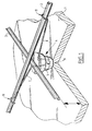
- Figure 1 shows a base 1 of a formwork which must be filled with concrete.
- a reinforcement is arranged comprising inter alia two mutually intersecting pieces of concrete reinforcing bar 2,3.
- the reinforcement is otherwise shown in its entirety in figure 3.
- the mutually intersecting pieces of reinforcing bar 2,3 are usually connected to each other at the location of the intersection, for instance by winding round iron wire, but this is less relevant to the application of the present invention. It will be apparent that the concrete reinforcing bars will have to be fully enclosed within the concrete for arranging round it, so that the reinforcing bars must be arranged at a distance from the formwork. Use is made for this purpose of the spacer according to the invention.
- the spacer according to the invention is formed in the first instance by a body 4 which is preferably manufactured from concrete.
- the body is substantially frusto-conical, wherein the smaller surface is adapted to rest on the formwork, while the larger surface is adapted to support a part of the reinforcing bars.
- a part of the body which is designated with 5 further takes a cylindrical form.
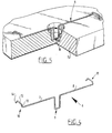
- the spacer is provided with a piece of wire 6, which is shown in its entirety in figure 4.
- the wire piece 6 is formed by two legs 7,8 which are connected by a part 9 bent into U-shape.
- the legs 7,8 lie mutually in line; it is likewise possible to have these legs extending mutually parallel but not mutually in line. Attachment to single pieces of concrete reinforcing bar is hereby improved.
- Hook 10 is for instance formed by a straight piece of wire 12 which extends perpendicularly of leg 7 and is connected thereto by means of a connection piece 13 which in turn extends perpendicularly of leg 7 and is connected at an angle of 45° to wire piece 12. Finally, wire piece 12 is connected, once again at an angle of 45°, to a last wire piece 13.
- the whole piece of wire 6 is connected to spacer body 4 in that the U-shaped part 9 is cast into the concrete of body 4, as shown in figure 5.
- the form of the hooks with the straight pieces of wire 11,12 serves to prevent the spacers according to the invention becoming mutually entangled with their hooks when they are tipped into a box or bag.
- legs 7,8 has the purpose of ensuring that the spacer can be fixed to concrete reinforcing bars of diverse form and diameter; the distance between the upper surface of body 4 and wire piece 11,12 is anyway variable to a large degree owing to the great length of legs 7,8.
- the shape of the wire piece 11,12 likewise results in a good attachment being obtained to reinforcing bars of the most varying form.
- the great length of the legs provides the possibility of attaching the spacer to concrete reinforcing bars at the position of intersections.
- body 4 can be picked up with one hand, wherein the first hook 10 can be hooked easily round the piece of reinforcing bar 2, whereafter the other hook can be arranged by manipulating body 4.
- Figure 2 shows an embodiment wherein the configuration of the body is simplified; the body has a purely conical form.
- figure 5 shows a casting mould 15 for casting the spacers; as shown in figure 5, a piece of wire 6 is herein initially placed in each of the cavities 16 in casting mould 15, whereafter cavity 16 can be filled with concrete. After sufficient curing the thus manufactured spacer can be removed.
Landscapes
- Engineering & Computer Science (AREA)
- Architecture (AREA)
- Civil Engineering (AREA)
- Structural Engineering (AREA)
- Reinforcement Elements For Buildings (AREA)
Applications Claiming Priority (2)
| Application Number | Priority Date | Filing Date | Title |
|---|---|---|---|
| NL1005831A NL1005831C2 (nl) | 1997-04-17 | 1997-04-17 | Afstandhouder voor betonijzer. |
| NL1005831 | 1997-04-17 |
Publications (2)
| Publication Number | Publication Date |
|---|---|
| EP0874098A1 true EP0874098A1 (fr) | 1998-10-28 |
| EP0874098B1 EP0874098B1 (fr) | 2003-10-29 |
Family
ID=19764804
Family Applications (1)
| Application Number | Title | Priority Date | Filing Date |
|---|---|---|---|
| EP98201242A Expired - Lifetime EP0874098B1 (fr) | 1997-04-17 | 1998-04-17 | Espaceur pour armatures de béton |
Country Status (4)
| Country | Link |
|---|---|
| EP (1) | EP0874098B1 (fr) |
| AT (1) | ATE253157T1 (fr) |
| DE (1) | DE69819236T2 (fr) |
| NL (1) | NL1005831C2 (fr) |
Cited By (4)
| Publication number | Priority date | Publication date | Assignee | Title |
|---|---|---|---|---|
| NL1012540C2 (nl) * | 1999-07-08 | 2001-01-15 | Molenaar Betonindustrie B V | Afstandhouder voor het op een voorafbepaalde afstand houden van een wapening ten opzichte van een gekozen vlak. |
| RU2175287C1 (ru) * | 2001-01-17 | 2001-10-27 | Акционерное общество открытого типа "Завод железобетонных изделий-6" | Способ и устройство для изготовления железобетонных изделий с каналами для электропроводки |
| ES2610796A1 (es) * | 2016-11-11 | 2017-05-03 | Baupanel System S.L | Procedimiento para hormigonar forjados y cubiertas de paneles estructurales de hormigón armado con núcleo de poliestireno expandido |
| CN110206222A (zh) * | 2019-05-15 | 2019-09-06 | 王启玲 | 一种新型保温拉结件 |
Citations (5)
| Publication number | Priority date | Publication date | Assignee | Title |
|---|---|---|---|---|
| DE2144093A1 (de) | 1971-09-02 | 1973-03-15 | Peter Gander | Abstandshalter fuer eine schalungsnahe armierung |
| DE2308765A1 (de) * | 1973-02-22 | 1974-09-05 | Helmut Jauch | Abstandshalter fuer die armierung von betonrohren |
| NL7601430A (nl) | 1975-02-20 | 1976-08-24 | Huebner Handel Huewa | Afstandhouder, in het bijzonder gevormd uit ge- goten, geperste of samengeperste materialen, zo- als beton, asbest of dergelijke materialen, met kleminrichting. |
| US4147008A (en) * | 1977-07-11 | 1979-04-03 | Horst Eisner | Resilient reinforcement spacer |
| CH619018A5 (en) * | 1977-06-02 | 1980-08-29 | Constri Beteiligungs Ag | Holder for fixing reinforcing-steel members |
-
1997
- 1997-04-17 NL NL1005831A patent/NL1005831C2/nl not_active IP Right Cessation
-
1998
- 1998-04-17 DE DE69819236T patent/DE69819236T2/de not_active Expired - Lifetime
- 1998-04-17 EP EP98201242A patent/EP0874098B1/fr not_active Expired - Lifetime
- 1998-04-17 AT AT98201242T patent/ATE253157T1/de not_active IP Right Cessation
Patent Citations (5)
| Publication number | Priority date | Publication date | Assignee | Title |
|---|---|---|---|---|
| DE2144093A1 (de) | 1971-09-02 | 1973-03-15 | Peter Gander | Abstandshalter fuer eine schalungsnahe armierung |
| DE2308765A1 (de) * | 1973-02-22 | 1974-09-05 | Helmut Jauch | Abstandshalter fuer die armierung von betonrohren |
| NL7601430A (nl) | 1975-02-20 | 1976-08-24 | Huebner Handel Huewa | Afstandhouder, in het bijzonder gevormd uit ge- goten, geperste of samengeperste materialen, zo- als beton, asbest of dergelijke materialen, met kleminrichting. |
| CH619018A5 (en) * | 1977-06-02 | 1980-08-29 | Constri Beteiligungs Ag | Holder for fixing reinforcing-steel members |
| US4147008A (en) * | 1977-07-11 | 1979-04-03 | Horst Eisner | Resilient reinforcement spacer |
Cited By (4)
| Publication number | Priority date | Publication date | Assignee | Title |
|---|---|---|---|---|
| NL1012540C2 (nl) * | 1999-07-08 | 2001-01-15 | Molenaar Betonindustrie B V | Afstandhouder voor het op een voorafbepaalde afstand houden van een wapening ten opzichte van een gekozen vlak. |
| RU2175287C1 (ru) * | 2001-01-17 | 2001-10-27 | Акционерное общество открытого типа "Завод железобетонных изделий-6" | Способ и устройство для изготовления железобетонных изделий с каналами для электропроводки |
| ES2610796A1 (es) * | 2016-11-11 | 2017-05-03 | Baupanel System S.L | Procedimiento para hormigonar forjados y cubiertas de paneles estructurales de hormigón armado con núcleo de poliestireno expandido |
| CN110206222A (zh) * | 2019-05-15 | 2019-09-06 | 王启玲 | 一种新型保温拉结件 |
Also Published As
| Publication number | Publication date |
|---|---|
| DE69819236T2 (de) | 2004-07-29 |
| ATE253157T1 (de) | 2003-11-15 |
| EP0874098B1 (fr) | 2003-10-29 |
| NL1005831C2 (nl) | 1998-11-05 |
| DE69819236D1 (de) | 2003-12-04 |
| NL1005831A1 (nl) | 1998-10-20 |
Similar Documents
| Publication | Publication Date | Title |
|---|---|---|
| US4498270A (en) | Support for positioning reinforcing rods or mesh in concrete or the like | |
| AU626137B2 (en) | Apparatus and method for lifting tilt-up wall constructions | |
| US6962029B2 (en) | Chair for supporting wire mesh | |
| US8312687B2 (en) | Support member for placing reinforcing bars | |
| US7950190B2 (en) | Concrete panel lifting insert assembly | |
| US6779312B2 (en) | Anchoring device | |
| US10837185B2 (en) | Lifting anchor assembly for precast concrete structures | |
| EP0874098B1 (fr) | Espaceur pour armatures de béton | |
| US20040088942A1 (en) | Cage spacer | |
| JPH0242809Y2 (fr) | ||
| US10132092B1 (en) | Recess insert for lift anchor assembly | |
| US20250305289A1 (en) | Reinforcing bar guide assembly | |
| AU2008203309B2 (en) | Anchoring Device | |
| AU606308B1 (en) | Braces for reinforcing mesh structures | |
| JP2002047760A (ja) | 鉄筋用スペーサ | |
| JP3954610B2 (ja) | 鉄筋用スペーサー | |
| CN222962342U (zh) | 一种新型钢筋保护层垫块 | |
| JP7007070B2 (ja) | 自立式l型鉄筋 | |
| RU1805183C (ru) | Железобетонна панель | |
| JPS5934657Y2 (ja) | 柱用鉄筋の間隔保持具 | |
| JPH074286Y2 (ja) | 棒状体支持具 | |
| JPS5851244Y2 (ja) | 杭と基礎とを結合する鉄筋篭 | |
| JPS601171Y2 (ja) | コンクリ−ト型枠引張支持用アンカ− | |
| JPS62129464A (ja) | Pc鋼材支持具 | |
| JPH067128Y2 (ja) | スペーサ |
Legal Events
| Date | Code | Title | Description |
|---|---|---|---|
| PUAI | Public reference made under article 153(3) epc to a published international application that has entered the european phase |
Free format text: ORIGINAL CODE: 0009012 |
|
| AK | Designated contracting states |
Kind code of ref document: A1 Designated state(s): AT BE CH DE DK ES FI FR GB GR IE IT LI NL PT SE |
|
| AX | Request for extension of the european patent |
Free format text: AL;LT;LV;MK;RO;SI |
|
| 17P | Request for examination filed |
Effective date: 19990330 |
|
| AKX | Designation fees paid |
Free format text: AT BE CH DE DK ES FI FR GB GR IE IT LI NL PT SE |
|
| AXX | Extension fees paid |
Free format text: RO PAYMENT 19990330 |
|
| 17Q | First examination report despatched |
Effective date: 20020726 |
|
| GRAH | Despatch of communication of intention to grant a patent |
Free format text: ORIGINAL CODE: EPIDOS IGRA |
|
| GRAS | Grant fee paid |
Free format text: ORIGINAL CODE: EPIDOSNIGR3 |
|
| GRAA | (expected) grant |
Free format text: ORIGINAL CODE: 0009210 |
|
| AK | Designated contracting states |
Kind code of ref document: B1 Designated state(s): AT BE CH DE DK ES FI FR GB GR IE IT LI NL PT SE |
|
| AX | Request for extension of the european patent |
Extension state: RO |
|
| PG25 | Lapsed in a contracting state [announced via postgrant information from national office to epo] |
Ref country code: LI Free format text: LAPSE BECAUSE OF FAILURE TO SUBMIT A TRANSLATION OF THE DESCRIPTION OR TO PAY THE FEE WITHIN THE PRESCRIBED TIME-LIMIT Effective date: 20031029 Ref country code: IT Free format text: LAPSE BECAUSE OF FAILURE TO SUBMIT A TRANSLATION OF THE DESCRIPTION OR TO PAY THE FEE WITHIN THE PRESCRIBED TIME-LIMIT;WARNING: LAPSES OF ITALIAN PATENTS WITH EFFECTIVE DATE BEFORE 2007 MAY HAVE OCCURRED AT ANY TIME BEFORE 2007. THE CORRECT EFFECTIVE DATE MAY BE DIFFERENT FROM THE ONE RECORDED. Effective date: 20031029 Ref country code: FI Free format text: LAPSE BECAUSE OF FAILURE TO SUBMIT A TRANSLATION OF THE DESCRIPTION OR TO PAY THE FEE WITHIN THE PRESCRIBED TIME-LIMIT Effective date: 20031029 Ref country code: CH Free format text: LAPSE BECAUSE OF FAILURE TO SUBMIT A TRANSLATION OF THE DESCRIPTION OR TO PAY THE FEE WITHIN THE PRESCRIBED TIME-LIMIT Effective date: 20031029 Ref country code: BE Free format text: LAPSE BECAUSE OF FAILURE TO SUBMIT A TRANSLATION OF THE DESCRIPTION OR TO PAY THE FEE WITHIN THE PRESCRIBED TIME-LIMIT Effective date: 20031029 Ref country code: AT Free format text: LAPSE BECAUSE OF FAILURE TO SUBMIT A TRANSLATION OF THE DESCRIPTION OR TO PAY THE FEE WITHIN THE PRESCRIBED TIME-LIMIT Effective date: 20031029 |
|
| REG | Reference to a national code |
Ref country code: GB Ref legal event code: FG4D |
|
| REG | Reference to a national code |
Ref country code: CH Ref legal event code: EP |
|
| REG | Reference to a national code |
Ref country code: IE Ref legal event code: FG4D |
|
| REF | Corresponds to: |
Ref document number: 69819236 Country of ref document: DE Date of ref document: 20031204 Kind code of ref document: P |
|
| PG25 | Lapsed in a contracting state [announced via postgrant information from national office to epo] |
Ref country code: SE Free format text: LAPSE BECAUSE OF FAILURE TO SUBMIT A TRANSLATION OF THE DESCRIPTION OR TO PAY THE FEE WITHIN THE PRESCRIBED TIME-LIMIT Effective date: 20040129 Ref country code: GR Free format text: LAPSE BECAUSE OF FAILURE TO SUBMIT A TRANSLATION OF THE DESCRIPTION OR TO PAY THE FEE WITHIN THE PRESCRIBED TIME-LIMIT Effective date: 20040129 Ref country code: DK Free format text: LAPSE BECAUSE OF FAILURE TO SUBMIT A TRANSLATION OF THE DESCRIPTION OR TO PAY THE FEE WITHIN THE PRESCRIBED TIME-LIMIT Effective date: 20040129 |
|
| PG25 | Lapsed in a contracting state [announced via postgrant information from national office to epo] |
Ref country code: ES Free format text: LAPSE BECAUSE OF FAILURE TO SUBMIT A TRANSLATION OF THE DESCRIPTION OR TO PAY THE FEE WITHIN THE PRESCRIBED TIME-LIMIT Effective date: 20040209 |
|
| PG25 | Lapsed in a contracting state [announced via postgrant information from national office to epo] |
Ref country code: IE Free format text: LAPSE BECAUSE OF NON-PAYMENT OF DUE FEES Effective date: 20040419 |
|
| REG | Reference to a national code |
Ref country code: CH Ref legal event code: PL |
|
| ET | Fr: translation filed | ||
| PLBE | No opposition filed within time limit |
Free format text: ORIGINAL CODE: 0009261 |
|
| STAA | Information on the status of an ep patent application or granted ep patent |
Free format text: STATUS: NO OPPOSITION FILED WITHIN TIME LIMIT |
|
| 26N | No opposition filed |
Effective date: 20040730 |
|
| REG | Reference to a national code |
Ref country code: IE Ref legal event code: MM4A |
|
| PG25 | Lapsed in a contracting state [announced via postgrant information from national office to epo] |
Ref country code: PT Free format text: LAPSE BECAUSE OF NON-PAYMENT OF DUE FEES Effective date: 20040329 |
|
| PGFP | Annual fee paid to national office [announced via postgrant information from national office to epo] |
Ref country code: DE Payment date: 20110429 Year of fee payment: 14 Ref country code: FR Payment date: 20110517 Year of fee payment: 14 |
|
| PGFP | Annual fee paid to national office [announced via postgrant information from national office to epo] |
Ref country code: GB Payment date: 20110503 Year of fee payment: 14 Ref country code: NL Payment date: 20110509 Year of fee payment: 14 |
|
| REG | Reference to a national code |
Ref country code: NL Ref legal event code: V1 Effective date: 20121101 |
|
| GBPC | Gb: european patent ceased through non-payment of renewal fee |
Effective date: 20120417 |
|
| REG | Reference to a national code |
Ref country code: FR Ref legal event code: ST Effective date: 20121228 |
|
| PG25 | Lapsed in a contracting state [announced via postgrant information from national office to epo] |
Ref country code: GB Free format text: LAPSE BECAUSE OF NON-PAYMENT OF DUE FEES Effective date: 20120417 |
|
| REG | Reference to a national code |
Ref country code: DE Ref legal event code: R119 Ref document number: 69819236 Country of ref document: DE Effective date: 20121101 |
|
| PG25 | Lapsed in a contracting state [announced via postgrant information from national office to epo] |
Ref country code: FR Free format text: LAPSE BECAUSE OF NON-PAYMENT OF DUE FEES Effective date: 20120430 |
|
| PG25 | Lapsed in a contracting state [announced via postgrant information from national office to epo] |
Ref country code: NL Free format text: LAPSE BECAUSE OF NON-PAYMENT OF DUE FEES Effective date: 20121101 |
|
| PG25 | Lapsed in a contracting state [announced via postgrant information from national office to epo] |
Ref country code: DE Free format text: LAPSE BECAUSE OF NON-PAYMENT OF DUE FEES Effective date: 20121101 |