EP0874163A2 - Ein zweikanaliges Doppelantriebssystem für einen Druckmittelstrom - Google Patents
Ein zweikanaliges Doppelantriebssystem für einen Druckmittelstrom Download PDFInfo
- Publication number
- EP0874163A2 EP0874163A2 EP98850062A EP98850062A EP0874163A2 EP 0874163 A2 EP0874163 A2 EP 0874163A2 EP 98850062 A EP98850062 A EP 98850062A EP 98850062 A EP98850062 A EP 98850062A EP 0874163 A2 EP0874163 A2 EP 0874163A2
- Authority
- EP
- European Patent Office
- Prior art keywords
- valve
- valves
- power
- drive
- end position
- Prior art date
- Legal status (The legal status is an assumption and is not a legal conclusion. Google has not performed a legal analysis and makes no representation as to the accuracy of the status listed.)
- Withdrawn
Links
Images


Classifications
-
- F—MECHANICAL ENGINEERING; LIGHTING; HEATING; WEAPONS; BLASTING
- F15—FLUID-PRESSURE ACTUATORS; HYDRAULICS OR PNEUMATICS IN GENERAL
- F15B—SYSTEMS ACTING BY MEANS OF FLUIDS IN GENERAL; FLUID-PRESSURE ACTUATORS, e.g. SERVOMOTORS; DETAILS OF FLUID-PRESSURE SYSTEMS, NOT OTHERWISE PROVIDED FOR
- F15B20/00—Safety arrangements for fluid actuator systems; Applications of safety devices in fluid actuator systems; Emergency measures for fluid actuator systems
- F15B20/001—Double valve requiring the use of both hands simultaneously
Definitions
- the present invention relates to a double drive system for a pressurized fluid flow, wherein the system includes two control units which each includes a drive device adapted for actuation by a separate control signal, wherein each control unit includes a power valve which is spring-biased towards a first end position and which can be driven to a second end position, wherein said two valves are mutually connected in series between a fluid pressure source and a pressurized fluid receiver, for delivering pressurized fluid to the receiver when said two valves are in their second positions.
- the control signals can be generated by an operator actuating the two drive devices, and therewith change their states, with one or both hands, either directly or through the medium of respective power amplifiers (pilot valves).
- the control signals may, for instance, be generated as a result of closing a safety gate that shields a danger area, thus changing the positions or staes of the two drive devices.
- the control signals may also be generated in some other way known within the technical field concerned.
- Drive systems of this particular kind will ideally fulfil a number of safety requirements.
- These requirements, or criteria can be summarized by saying that all system elements shall be duplicated, therewith providing said systems with a desired redunancy, such that each control unit will be independent of the other control unit. All elements will also preferably be monitored at least once with each cycle. It will preferably also be possible to interrupt the operation controlled by the system should one of the drive devices be released, and therewith prevent continued operation until both drive devices have been released and again re-actuated. It shall also be possible to start-up the system immediately, without first needing to prime the system.
- an object of the present invention is to provide a drive system in which all the requirements placed on such a system can be fulfilled in all essentials.
- Another object of the invention is to provide an essentially simple drive system.
- Still another object of the invention is to provide a drive system that can be fully pneumatic when the fluid flow controlled by the system has a pneumatic nature.
- Yet another object of the invention is to provide a control system which requires the drive devices of said two control units to be actuated within a specific time period in order for the receiver to receive its fluid flow.
- the inventive control system includes two control units which are basically comprised of mutually identical elements that are connected in essentially the same way, wherein each control unit includes a drive device that is actuated by a control signal.
- the drive device switches a power valve from its first to its second position. Switching of the power valve is detected by a monitoring valve which in response thereto switches from one position/its normal position to its second position in which fluid from the pressure source is caused to flow through the monitoring valve to the power valve, via said drive device, so as to ensure that said power valve is kept in its activated, second position for as long as the drive device is held actuated by the operator.
- the system is designed so that the drive unit can only execute a working movement when both of the power valves are set to their 1-positions.
- these two power valves control a respective monitoring valve which when in their 0-positions permit the accumulators to be charged and to deliver a holding signal (air) to the valves of the drive devices.
- the power valves are set briefly in a first phase, by evacuating the accumulators (due to actuation of the drive devices). Resetting of the power valves (i.e. re-setting of the monitoring valves) causes holding signals (air) to be delivered via the drive devices for actuation of the power valves, provided that the two drive devices are held actuated by a control signal (for instance, each held depressed by a respective hand of the operator).
- Figure 1 shows a double, two-channel, fully pneumatic drive system for controlling a drive unit, for instance a linear drive unit, such as a pneumatic press cylinder.
- a drive unit for instance a linear drive unit, such as a pneumatic press cylinder.
- the drive system includes two control units 1, 1'.
- the control units 1, 1' are comprised of essentially the same components and the components are coupled or interconnected in essentially the same manner.
- the unit 1 includes a drive device 3 comprised of two parallel-connected drive valves 31, 32 that are spring biased towards a non-actuated position.
- a drive signal can be delivered to the unit 1, for instance by the operator actuating both of the valves 31, 32 in the drive device 3 simultaneously, via a bridge 33.
- a control signal can be delivered to the other unit 1', for instance by the operator actuating the bridge 33' with his other hand.
- Each unit 1, 1' includes a respective accumulator 4, 4' which can be charged from a compressed-air source 11 via a monitoring valve 7, 7' and via the two drive valves 31, 32 of the unit concerned in series with said monitoring valve, provided that the monitoring valve is also in its position in which its power valve is in its non-actuated first position.
- the accumulator 4 is discharged through the one valve 32 to the switch valve 5' in the other control unit 1' and the switch valve 5' then activates the power valve 6'.
- the accumulator 4 contains a small and limited volume of air and the discharge passageway between the accumulator and the switch valve has a throttled outlet 51 so that the volume of air contained by the accumulator will only be able to hold the power valve 6 in an activated state over a short period of time determined by the setting of the throttle 51 and the pressure and volume of the accumulator.
- the power valve 6 When activated, the power valve 6 sets the monitoring valve 7 to its activated state (pneumatically in the illustrated example) wherein compressed air is conducted from the source 11 in series through the monitoring valve 7 and the two activated drive valves 31, 32 to the other input of the switch valve 5, so as to enable the power valve to be held in an activated position when the valve 5 is supplied with air from the source 11 prior to air from the accumulator 4 having leaked away through the throttle 51 to an extent at which the valve has been able to return to its position.
- the monitoring valve 7 to its activated state (pneumatically in the illustrated example) wherein compressed air is conducted from the source 11 in series through the monitoring valve 7 and the two activated drive valves 31, 32 to the other input of the switch valve 5, so as to enable the power valve to be held in an activated position when the valve 5 is supplied with air from the source 11 prior to air from the accumulator 4 having leaked away through the throttle 51 to an extent at which the valve has been able to return to its position.
- the switch valve 5 is unable to seriously malfunction in practice, and because of its intrinsic properties need not therefore be monitored.
- Charging air is delivered from the compressed-air source 11 to the accumulator 4, 4' in respective units 1, 1', via an accumulator charging line 9, 9', and is led in series through respective monitor valves 7, 7' when said valves are in a position or state that indicates that the associated power valves are in said one position and the drive valves of the unit are in said first position.
- the secondary side of the cylinder 10 has an outlet line 12 in which the power valves 6, 6' are connected in series such that the line 12 will be evacuated to atmosphere only when both power valves 6, 6' have been switched to their activated, second position. It will also be seen that compressed air is delivered from the source 11 to the secondary side of the power unit 10 via the line 12 when one or both of the valves 6, 6' is in a first position.
- the aforesaid fluid control to and from the primary and secondary side of the power unit 10 respectively is achieved with full monitoring of all of the valves involved, even though both power valves 6, 6' and the monitoring valves 7, 7' are standard 5/2-valves.
- the two drive valves 31, 32 may also be standard 5/2-valves.
- the power valve 6' has been connected so that when said valve is in its non-actuated state it will hold the associated monitoring valve 7' in said one position against the action of its restoring spring.
- the other power valve 6 is connected to its monitoring valve 7 in the reverse manner, so that the valve 7 will be held in said one position by its biasing spring when the power valve 6 is in its non-actuated state, and is driven to its second position when the valve 6, 6' is re-set, for instance by air that is released through by the valve 6 when said valve is actuated to its second position, or by means of a mechanical coupling between the valves 6, 7.
- the embodiment illustrated in Figure 2 corresponds to the embodiment illustrated in Figure 1 (and in Figure 3) with the following exceptions.
- the line to the secondary side of the power unit or power cylinder 10 is connected to the pressure source 11 via a pressure regulator 14 that includes a manometer 15.
- the regulator 14 can be set to establish a desired pressure on the secondary side of the power unit 10, such as a "restoring spring" for the piston of the cylinder 10.
- a tank 16 is connected to the line 12 for reducing variations in pressure as the piston moves.
- the tank 16 includes a safety valve 17 which limits the pressure in the line 12 to a pre-set value. Because the power valves 6, 6' are not used to control the line 12, the monitoring valves 7, 7' can be connected in the same way as their respective power valves 6, 6'.
- the drive valves 31, 32, the monitoring valve 7 and the power valve 6 may be standard 5/2-valves also in the case of the Figure 2 embodiment.
- the drive system includes a cross-coupling with which air discharged from the accumulator 4 of one unit 1 is transferred to the switch valve 5' of the other unit 1', and vice versa. Because of this cross-coupling between the units 1, 1' there is achieved the situation in which the start impulse (the volume of air discharged) from the accumulator 4' via the switch valve 5 to a power valve 6 in one unit 1 is obtained from the other unit 1', whereas the holding signal for the valve 6 is obtained from the unit 1 (via the valve 7, 31, 32, 5), and vice versa.
- the volume of air in the accumulator 4 and the throttling extent of the throttle 51 are set to establish a time period (e.g. 0.5 sec after actuation of the drive device 3) within which air must be delivered to the switch valve 5, via the valves 31, 32, 7, in order to enable the power valve of the control unit to be held in its activated position.
- a time period e.g. 0.5 sec after actuation of the drive device 3
- the two units 1, 1' are set to the same time period. It will be understood that both of the drive devices 3, 3' must be actuated within this period, in order for air to be supplied to the power unit 10.
- the switch valve 5 may have the form of a tubular conduit that includes two opposing valve seats 53 between which a ball 55 is able to move under the influence of the flow from the valve 31 or from the valve 32, such that the flow occurring between the seats 53 will depart to the power valve 6 via a line, or conduit, connected between the seats.
- the throttle 51 is set to release air that has been supplied to the switch valve from the accumulator 4 within the current time period, to an extent such that the power-valve restoring spring is able to return the power valve 6 to its said one position.
- Spring biasing of the individual valves towards their respective first end positions can be established in any convenient manner, for instance with the aid of a mechanical or a pneumatic spring.
- the embodiment illustrated in Figure 1 involves connecting two standard 5/2-valves in a manner to obtain a series connection to one side of the cylinder 10 and a parallel connection to the other side of the cylinder. It is ensured in the case of the Figure 2 embodiment that the power unit or cylinder 10 will always be returned to its starting state.
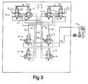
- Figures 3, 4 show pairs of drive valves which are designed to permit respective accumulators 4, 4' to be charged from a compressed-air source 11 via the monitoring valve 7 in its end position in which it is not actuated by the power valve 6, in one non-actuated position of the drive valves.
- This embodiment includes a branched conduit 90 which leads air from the accumulator 4 through the second drive valve 31 and further through the second drive valve 32' of the second unit 1' (when said drive valve is actuated and switched to its second end position) and out to atmosphere via the monitoring valve 7' of the second unit 1' when said monitoring valve in its second position actuated by the power valve 6'. The volume of air in the accumulator will then be expelled to atmosphere.
- the branch conduit 91 also includes a throttle 51', which is preferably positioned between the drive valve 32' and the monitoring valve 7'.
- the throttle 51' ensures that the accumulator 4 is able to hold the power valve 6' switched over a selected time period of up to, e.g., 0.5 sec, before the restoring means (e.g. a spring) of the power valve 6' can return said valve to its starting position.
- both drive devices 3, 3' are actuated simultaneously with a time difference within the selected time period, both power valves can be held in a switched position provided that the drive devices are kept actuated.
- Air from a compressed-air source can pass in series through an open port in each of the power valves 6, 6' to the cylinder or power unit 10, provided that the power valves 6, 6' are in their respective second positions.
- the return line of the power unit or cylinder 10 is, instead, connected to a return spring of the same kind as that described with reference to and shown in Figure 2.
- the inventive system can be said to include two units that form respectively a left side and a right side in the system.
- Each unit includes three component groups, namely a group 3, 8; 3', 8' that receives control signals, e.g. manually actuated signals, a power valve arrangement 6; 6' which allows energy to be supplied to a power unit 10, and a monitoring valve arrangement 7; 7' which delivers a status report with respect to the supply of energy to the power unit 10.
- control signals e.g. manually actuated signals
- a power valve arrangement 6; 6' which allows energy to be supplied to a power unit 10
- a monitoring valve arrangement 7; 7' which delivers a status report with respect to the supply of energy to the power unit 10.
- the method of operation of the arrangement shown in Figures 3 and 4 can be described in the following way.
- the two accumulators 4, 4' are charged with energy from the monitoring valve 7, 7' when said valves are in their respective zero-positions.
- the respective zero-positions and 1-positions of the power valves 6, 6' are reflected by the monitoring valves 7, 7'.
- One condition for charging the accumulators is that all drive valves 31, 32, 81, 82; 31', 32', 81', 82' are in their respective 0-positions.
- the energy stored in respective accumulators is released over a time period that has a maximum duration of, e.g., 0.5 sec.
- This energy pulse switches the positions of the valves 6, 6', wherewith the power unit 10 starts.
- the valves 7, 7' are switched at the same time.
- the valves 7, 7' are switched, the valves allow a power valve holding signal to pass through, via the valves 32', 31; 32, 31'.
- the power unit 10 continues to work as long as all of the valves 31, 32, 31', 32' are actuated.
- valve 6 When the contents of the accmulator 4' are evacuated to the valve 6, this valve is switched and also the valve 7 which held the accumulator 4 filled with air. Thus, the contents of the accumulator 4 must be evacuated to valve 6' prior to the energy content of the accumulator 4' being discharged to atmosphere through the valve 7.
- the throttle 51' functions to maintain pressure in the conduit 91 between the accumulator 4' and the power valve 6 over a time period of such duration as to enable resetting of the valve 7 to have time to deliver maintenance pressure to the power valve 6 through the throttle 51' in the other direction through the conduit 91' and the valve 31'.
- the throttle is blown clean in this way, since air is blown through the throttle from both directions in each cycle.
- valve 6 When only the valve 32' is actuated to its 1-position, the valve 6 is unable to switch over, since the accumulator 4' is evacuated through the port 1 of the drive valve 31'. If the valve 32' is deactivated during the holding signal phase, the signal air will pass through the monitoring valve 7 and the throttle 51' and be evacuated through the port 2 of the valve 32', since the throttle 51' will not provide the flow that is required to maintain the pressure from the throttle 51' through 31' to the power valve 6. If the drive valve 31' is deactivated during the holding signal phase, the signal that controls the power valve 6 will be evacuated via the port 2 of the drive valve 31'. Compressed air is delivered to the power unit 10, when both of the power valves 6, 6' are in their respective 1-positions. If one of the valves 6, 6' takes its 0-position, the plus chamber of the drive unit will be evacuated and the piston of the working cylinder retracted.
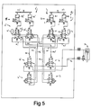
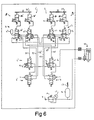
- the systems illustrated in Figures 5 and 6 are based on the systems illustrated in Figures 3 and 4 and show that the drive valves 31, 32; 31', 32' have been provided with servo valves 81, 82; 81', 82'.
- the respective pairs of servo valves 8, 8' are actuated simultaneously by an associated bridge 33, 33' which, in turn, is actuated by a respective hand of the operator, or some corresponding means.
- the servo valves are preferably 3/2- valves which can be switched between positions by means of a small force and each of which controls a respective drive valve 31, 32; 31', 32', which may be a 5/2-valve that requires relatively high switching power.
Landscapes
- Engineering & Computer Science (AREA)
- Fluid-Pressure Circuits (AREA)
- Chemical & Material Sciences (AREA)
- Analytical Chemistry (AREA)
- Physics & Mathematics (AREA)
- Fluid Mechanics (AREA)
- Mechanical Engineering (AREA)
- General Engineering & Computer Science (AREA)
- Manipulator (AREA)
Applications Claiming Priority (2)
| Application Number | Priority Date | Filing Date | Title |
|---|---|---|---|
| SE9701523 | 1997-04-23 | ||
| SE9701523A SE507552C2 (sv) | 1997-04-23 | 1997-04-23 | Tvåhandsmanöversystem |
Publications (2)
| Publication Number | Publication Date |
|---|---|
| EP0874163A2 true EP0874163A2 (de) | 1998-10-28 |
| EP0874163A3 EP0874163A3 (de) | 1999-03-17 |
Family
ID=20406693
Family Applications (1)
| Application Number | Title | Priority Date | Filing Date |
|---|---|---|---|
| EP98850062A Withdrawn EP0874163A3 (de) | 1997-04-23 | 1998-04-23 | Ein zweikanaliges Doppelantriebssystem für einen Druckmittelstrom |
Country Status (2)
| Country | Link |
|---|---|
| EP (1) | EP0874163A3 (de) |
| SE (1) | SE507552C2 (de) |
Cited By (12)
| Publication number | Priority date | Publication date | Assignee | Title |
|---|---|---|---|---|
| US8080029B2 (en) | 2007-09-21 | 2011-12-20 | Novartis Ag | System for actuation of a vitreous cutter |
| US8162000B2 (en) | 2006-12-13 | 2012-04-24 | Novartis Ag | Adjustable pneumatic system for a surgical machine |
| US8312800B2 (en) | 2006-12-21 | 2012-11-20 | Novartis Ag | Pneumatic system for a vitrector |
| US8666556B2 (en) | 2009-12-10 | 2014-03-04 | Alcon Research, Ltd. | Systems and methods for dynamic feedforward |
| US8679241B2 (en) | 2006-10-30 | 2014-03-25 | Novartis Ag | Gas pressure monitor for pneumatic surgical machine |
| US8728108B2 (en) | 2009-12-10 | 2014-05-20 | Alcon Research, Ltd. | Systems and methods for dynamic pneumatic valve driver |
| US8808318B2 (en) | 2011-02-28 | 2014-08-19 | Alcon Research, Ltd. | Surgical probe with increased fluid flow |
| US8818564B2 (en) | 2009-08-31 | 2014-08-26 | Alcon Research, Ltd. | Pneumatic pressure output control by drive valve duty cycle calibration |
| US8821524B2 (en) | 2010-05-27 | 2014-09-02 | Alcon Research, Ltd. | Feedback control of on/off pneumatic actuators |
| US9060841B2 (en) | 2011-08-31 | 2015-06-23 | Alcon Research, Ltd. | Enhanced flow vitrectomy probe |
| US9241830B2 (en) | 2006-12-15 | 2016-01-26 | Novartis Ag | Pressure monitor for pneumatic vitrectomy machine |
| US10070990B2 (en) | 2011-12-08 | 2018-09-11 | Alcon Research, Ltd. | Optimized pneumatic drive lines |
Families Citing this family (1)
| Publication number | Priority date | Publication date | Assignee | Title |
|---|---|---|---|---|
| SE9901670L (sv) * | 1999-05-07 | 2000-05-22 | Rudolf Westerberg Ab | Dubblerat tvåkanaligt, pneumatiskt styrsystem |
Family Cites Families (5)
| Publication number | Priority date | Publication date | Assignee | Title |
|---|---|---|---|---|
| DE1426512B2 (de) * | 1964-02-13 | 1971-10-07 | Henon Werke KG, 7012 Fellbach | Servosteuerung fuer einen druckverbraucher insbesondere fuer die kupplung oder bremse eines pressenantriebes |
| DE9014789U1 (de) * | 1990-10-25 | 1991-02-07 | Herion-Werke Kg, 7012 Fellbach | Sicherheitsventil |
| US5113907A (en) * | 1991-01-29 | 1992-05-19 | Ross Operating Valve Company | Dynamic self-monitoring air operating system |
| DE9202938U1 (de) * | 1992-03-05 | 1992-05-07 | Herion-Werke Kg, 7012 Fellbach | Sicherheitsventil |
| DE9406561U1 (de) * | 1994-04-20 | 1994-07-14 | Herion-Werke KG, 70736 Fellbach | Sicherheitsventil |
-
1997
- 1997-04-23 SE SE9701523A patent/SE507552C2/sv not_active IP Right Cessation
-
1998
- 1998-04-23 EP EP98850062A patent/EP0874163A3/de not_active Withdrawn
Cited By (13)
| Publication number | Priority date | Publication date | Assignee | Title |
|---|---|---|---|---|
| US8679241B2 (en) | 2006-10-30 | 2014-03-25 | Novartis Ag | Gas pressure monitor for pneumatic surgical machine |
| US9326826B2 (en) | 2006-10-30 | 2016-05-03 | Novartis Ag | Gas pressure monitor for pneumatic surgical machine |
| US8162000B2 (en) | 2006-12-13 | 2012-04-24 | Novartis Ag | Adjustable pneumatic system for a surgical machine |
| US9241830B2 (en) | 2006-12-15 | 2016-01-26 | Novartis Ag | Pressure monitor for pneumatic vitrectomy machine |
| US8312800B2 (en) | 2006-12-21 | 2012-11-20 | Novartis Ag | Pneumatic system for a vitrector |
| US8080029B2 (en) | 2007-09-21 | 2011-12-20 | Novartis Ag | System for actuation of a vitreous cutter |
| US8818564B2 (en) | 2009-08-31 | 2014-08-26 | Alcon Research, Ltd. | Pneumatic pressure output control by drive valve duty cycle calibration |
| US8666556B2 (en) | 2009-12-10 | 2014-03-04 | Alcon Research, Ltd. | Systems and methods for dynamic feedforward |
| US8728108B2 (en) | 2009-12-10 | 2014-05-20 | Alcon Research, Ltd. | Systems and methods for dynamic pneumatic valve driver |
| US8821524B2 (en) | 2010-05-27 | 2014-09-02 | Alcon Research, Ltd. | Feedback control of on/off pneumatic actuators |
| US8808318B2 (en) | 2011-02-28 | 2014-08-19 | Alcon Research, Ltd. | Surgical probe with increased fluid flow |
| US9060841B2 (en) | 2011-08-31 | 2015-06-23 | Alcon Research, Ltd. | Enhanced flow vitrectomy probe |
| US10070990B2 (en) | 2011-12-08 | 2018-09-11 | Alcon Research, Ltd. | Optimized pneumatic drive lines |
Also Published As
| Publication number | Publication date |
|---|---|
| EP0874163A3 (de) | 1999-03-17 |
| SE9701523L (sv) | 1998-06-22 |
| SE9701523D0 (sv) | 1997-04-23 |
| SE507552C2 (sv) | 1998-06-22 |
Similar Documents
| Publication | Publication Date | Title |
|---|---|---|
| EP0874163A2 (de) | Ein zweikanaliges Doppelantriebssystem für einen Druckmittelstrom | |
| US9651068B2 (en) | Double valve constructed from unitary single valves | |
| JPH0794843B2 (ja) | 空気制御装置 | |
| US4590763A (en) | Method of supplying a normally continuous operating hydraulic actuator with hydraulic fluid, continuously and by controlled pulse, and a device for implementing said method | |
| JPH059642B2 (de) | ||
| US5796571A (en) | Control device for a two-hand control means for controlling presses for instance | |
| US5799561A (en) | Control device | |
| US5912795A (en) | Circuit reset lockout | |
| JP2002054606A (ja) | 電気式油圧回路用ベント管路装置 | |
| EP0782057B1 (de) | Steuereinrichtung eines Doppelventils | |
| US11556141B2 (en) | Valve arrangement | |
| CA2221173C (en) | A method in a pneumatic oscillating device to observe an obstacle and to continue oscillating and corresponding oscillating device | |
| AU2004242500B2 (en) | Piezoelectric actuator unit | |
| KR20230158421A (ko) | 로봇용 선회 조인트 | |
| EP1177400A1 (de) | Zweikanaliges pneumatisches doppelsteuersystem | |
| JPH0522503Y2 (de) | ||
| SE507553C2 (sv) | Tvåhandsmanöversystem | |
| US4328829A (en) | Universal module for pneumatic fixed-cycle control | |
| JP3187196B2 (ja) | アクチュエータ制御装置 | |
| JPH05106605A (ja) | シリンダ駆動用流体回路 | |
| JPH04366001A (ja) | 油圧駆動式高圧流体発生装置 | |
| US3540460A (en) | Safety control | |
| SU973956A1 (ru) | Пневмогидравлический привод зажимных приспособлений | |
| GB2636823A (en) | Alert system and method | |
| GB2636824A (en) | Pneumatic lifting system and method |
Legal Events
| Date | Code | Title | Description |
|---|---|---|---|
| PUAI | Public reference made under article 153(3) epc to a published international application that has entered the european phase |
Free format text: ORIGINAL CODE: 0009012 |
|
| AK | Designated contracting states |
Kind code of ref document: A2 Designated state(s): BE CH DE DK ES FR GB IT LI SE |
|
| AX | Request for extension of the european patent |
Free format text: AL;LT;LV;MK;RO;SI |
|
| PUAL | Search report despatched |
Free format text: ORIGINAL CODE: 0009013 |
|
| AK | Designated contracting states |
Kind code of ref document: A3 Designated state(s): AT BE CH CY DE DK ES FI FR GB GR IE IT LI LU MC NL PT SE |
|
| AX | Request for extension of the european patent |
Free format text: AL;LT;LV;MK;RO;SI |
|
| AKX | Designation fees paid |
Free format text: BE CH DE DK ES FR GB IT LI SE |
|
| STAA | Information on the status of an ep patent application or granted ep patent |
Free format text: STATUS: THE APPLICATION IS DEEMED TO BE WITHDRAWN |
|
| 18D | Application deemed to be withdrawn |
Effective date: 19990918 |