EP0874270B1 - Transporteur pour appareil de traitement photographique - Google Patents
Transporteur pour appareil de traitement photographique Download PDFInfo
- Publication number
- EP0874270B1 EP0874270B1 EP98105890A EP98105890A EP0874270B1 EP 0874270 B1 EP0874270 B1 EP 0874270B1 EP 98105890 A EP98105890 A EP 98105890A EP 98105890 A EP98105890 A EP 98105890A EP 0874270 B1 EP0874270 B1 EP 0874270B1
- Authority
- EP
- European Patent Office
- Prior art keywords
- photo
- sensitive material
- conveyor
- section
- processing apparatus
- Prior art date
- Legal status (The legal status is an assumption and is not a legal conclusion. Google has not performed a legal analysis and makes no representation as to the accuracy of the status listed.)
- Expired - Lifetime
Links
Images




Classifications
-
- G—PHYSICS
- G03—PHOTOGRAPHY; CINEMATOGRAPHY; ANALOGOUS TECHNIQUES USING WAVES OTHER THAN OPTICAL WAVES; ELECTROGRAPHY; HOLOGRAPHY
- G03B—APPARATUS OR ARRANGEMENTS FOR TAKING PHOTOGRAPHS OR FOR PROJECTING OR VIEWING THEM; APPARATUS OR ARRANGEMENTS EMPLOYING ANALOGOUS TECHNIQUES USING WAVES OTHER THAN OPTICAL WAVES; ACCESSORIES THEREFOR
- G03B27/00—Photographic printing apparatus
- G03B27/32—Projection printing apparatus, e.g. enlarger, copying camera
-
- G—PHYSICS
- G03—PHOTOGRAPHY; CINEMATOGRAPHY; ANALOGOUS TECHNIQUES USING WAVES OTHER THAN OPTICAL WAVES; ELECTROGRAPHY; HOLOGRAPHY
- G03D—APPARATUS FOR PROCESSING EXPOSED PHOTOGRAPHIC MATERIALS; ACCESSORIES THEREFOR
- G03D13/00—Processing apparatus or accessories therefor, not covered by groups G11B3/00 - G11B11/00
- G03D13/003—Film feed or extraction in development apparatus
Definitions
- the present invention relates to a conveyor for conveying a photo-sensitive material along a conveying path from a first processing section to a second processing section, for example, from an exposing section to a developing section.
- Fig. 9 is an enlarged cross sectional view of an exposing section 11 and a part of a developing section 12 of a photo-processing apparatus.
- a photo-sensitive material 10 which is roll-shaped and wound at a magazine 9, is fed by a feed roller, cut into lengths corresponding to each frame by a cutter 1 and then the photo-sensitive material 10 is sent onto an exposing table 2.
- the exposing table 2 is provided with an endless adsorptive belt 3 which circulates along a triangular path composed of three rollers disposed at each vertex.
- the photo-sensitive material 10 is sent to a predetermined position by the movement of the belt 3 in a direction shown by an arrow A in Figure 9.
- the adsorptive belt 3 is provided with a plurality of small apertures and the photo-sensitive material 3 is adsorbed to the adsorptive belt 3 by providing a vacuum to the underside of the belt 3.
- the photo-sensitive material 10 sent to the predetermined position on the exposing table 2 is exposed and printed with an image on a film 8 held in a negative-mask 6 using a light from a light source 4 projected through a mirror tunnel 5, a negative mask 6, a lens unit 7 and so on. After being exposed and printed, the photo-sensitive material 10 is sent to the next stage of the developing section 12 by a conveyor 13.
- Fig. 11 is a plan view of the photo processing apparatus.
- the conveying path at the exposing section 11 shown by an arrow B in Fig. 11 is laterally offset from the conveying path at the developing section 12 shown by an arrow C in Fig. 11.
- the lateral direction is defined as a direction shown by an arrow X in Figs. 10 and 11 and it is substantially perpendicular to the conveying paths at each of the sections 11 and 12 shown by the arrows B and C in Fig. 11.
- the reason for the lateral offset is that the exposing section 11 can not be displaced at a space 14 in Fig. 11 where a reservoir or effluent tank for the developing section 12 is displaced.
- the height at which the photo-sensitive material 10 is taken out of the exposing section 11 is lower than a height at which the photo-sensitive material is brought into the developing section 12.
- the height of the inlet of the developing section 12 is higher than the height of the outlet of the exposing section 11.
- conveying the photo-sensitive material from the exposing section 11 to the developing section 12 needs a lateral conveyance shown by the arrow X and a vertical conveyance shown by an arrow Y in Fig. 9.
- the conveyor 13 is equipped to assist these conveyances.
- Fig. 10 is an external perspective view of the conveyor 13.
- the conveyor 13 comprises a frame 16.
- the frame 16 rotationally holds a plurality of roller pairs 15 and holds a motor 17.
- the motor 17 drives the roller pairs 15 through an endless belt not shown.
- the frame 16 itself is attached to an endless belt 18.
- the endless belt 18 is driven by a motor 19 in the direction of the arrow X.
- the frame 16 is guided in the direction of the arrow X by a pair of upper and lower slide rails 20 connected with the frame 16 by a slidable connection.
- a tank 21 is divided into several compartments by a plurality of partition boards 22. Each compartment is equipped with a rack which horizontally supports a plurality of roller pairs 23 for conveying the photo-sensitive material 10 in the tank 21 and is driven by a driving mechanism not shown. Between the conveyor 13 and the developing section 12 there are also rollers 24 for sending the photo-sensitive material 10 into the tank 21.
- the conveyance from the exposing section (a first processing section) to the developing section (a second processing section) needs to be accomplished with both vertical conveyance and lateral conveyance.
- the vertical conveyance is executed by driving the roller pairs with the motor.
- the lateral conveyance is executed by driving the endless belt with the motor to slide the roller pairs.
- the conveyor for the photo-processing increases in cost due to use of two types of motors, one for the lateral conveyance and one for the vertical conveyance of the photo-sensitive material as well as the complexity of the structure of the conveyor.
- the large number of the rollers for the vertical conveyance increase the cost.
- US-A-4 864 355 discloses an apparatus for the production of photographic copies comprising a film processor, or printer, a paper processor and a film and paper dryer. Individual sheets from the copy material which are exposed in the printer are transferred to a sheet turner by conveyor rolls. Subsequently the sheet turner is pivoted by 90° and the paper is transferred to the paper processor by another set of conveyor rolls.
- GB 2 103 812 A discloses an apparatus for conveying photosensitive material in which the exposed photosensitive material is withdrawn from an exposure zone in a direction at right angles to that at which the material is fed to the zone.
- a web of photosensitive material is fed from a roll, past a cutter, to an exposure station comprising a plate having suction apertures; and the exposed material is conveyed, after cutting, by means of an arm driven by an endless chain to take-up rollers leading to a development station.
- US-A-4 968 014 discloses a transport apparatus for transporting media and various size sheets processed at a first processing station to a second processing station.
- the apparatus comprises as main components thereof, a plurality of trays disposed between the first an second processing stations, each for accommodating media sheets of one size stacked one upon another.
- a first transport device for receiving media from the first processing station and transporting the media to the trays and a second transport device associated with the trays for successfully transporting the media from the trays to the second processing station.
- US-A-4 903 100 discloses a long-strip material handling apparatus which handles and transports a long strip materials between a first processing section, with a first transporting roller assembly which transports a long strip material lengthwise at a first speed therein, and a second processing section with a second transporting roller assembly which transports the long strip material lenghtwise at a second speed different from the first speed, the strip material passing through a reservoir section with a guide member disposed between the first and second processing section for temporarily reserving the long an narrow strip material therein in the form of a loop.
- the long strip material handling apparatus includes a speed changing mechanism for changing the speed of lengthwise transportation of the long strip material to the first or second speed before the leading end on the long strip material passes through the second transporting roller assembly when the second transporting roller assembly first threads the leading end of the long strip material, and a leader sensor for detecting the leading end of the threaded long strip material to provide a signal in response to which the speed mechanism is deactuated.
- EP 0 854 387 A1 discloses a photoprocessing apparatus having an exposing section and a developing section.
- a predetermined treatment of the photosensitive material is executed by conveying it along a conveying path through the exposing section and then through the developing section.
- a pair of rollers for nipping the photosensitive material and a drive unit for conveying the pair of rollers with the nipped photosensitive material along a conveying path are installed in the apparatus.
- a conveyor for photo-processing with a reduced number of rollers for vertical conveyance of the photo-sensitive material.
- a conveyor for a photo-processing apparatus having a first processing section and a second processing section are provided.
- the first processing section is an exposing section for printing an image from a photographic film on the photo-sensitive material
- the second processing section is a developing section for developing the exposed photo-sensitive material. It is certain that these processing sections are not restricted as mentioned above.
- the conveyor comprises the features defined in claim 1.
- This conveyor includes a power source for conveying a photo-sensitive material from the first processing section to the second processing section in a vertical direction and a guide mechanism for guiding the conveyed photo-sensitive material with the power source in a lateral direction.
- the lateral guidance of the photo-sensitive material with the guide mechanism is interlocked with the vertical conveyance with the power source.
- This conveyor can also include a power source for conveying the photo-sensitive material from the first processing section to the second processing section in the lateral direction and a guide mechanism for guiding the conveyed photo-sensitive material with the power source in the vertical direction.
- the vertical guidance of the photo-sensitive material with the guide mechanism is interlocked with the lateral conveyance with the power source.
- the conveyance of the photo-sensitive material it is particularly preferable to install a pair of nipping rollers for nipping the photo-sensitive material and a holder for rotationally supporting the nipping rollers.
- the photo-sensitive material is conveyed while being nipped by the nipping rollers.
- first slider for vertically sliding the photo-sensitive material
- second slider for laterally sliding the photo sensitive material
- third slider for sliding the photo-sensitive material in a direction defined between the lateral and vertical directions.
- first and second sliders guide bars are described.
- third slider a guide rail and guide rollers are also described.
- the conveying path from the first processing section to the second processing section it is particularly preferable to construct the conveying path so that it includes a portion elongated in a direction defined between the lateral direction and the vertical direction.
- Figs. 1-7 show a first embodiment of the present invention.
- Figs. 1-4 an exposing section 11 and a conveyor 13 of a photo processing apparatus are shown.
- the basic construction of the exposing section 11 is similar to that in Fig. 9 and the detailed description will be omitted and the same reference numerals and symbols are used as those in Figs. 9-11.
- On each vertex of a triangle formed by an adsorptive belt 3 are disposed roller pairs 34, 35 and 36 respectively.
- a photo-sensitive material 10 is conveyed from the left side to the right side as shown by an arrow B in Fig. 1.
- the pair of rollers 34 on the downstream side of the exposing section 30 comprise a press roller 34a and a drive roller 34b.
- a conveyor 13 is installed on the downstream side thereof.
- the conveyor comprises a lower holding roller 40; an upper holding roller 41; a guide member 42 for guiding the photo-sensitive material 10 to the pair of rollers 40 and 41; a first roller holding table 43 which rotationally holds the pair of rollers 40 and 41 and to which the guide member 42 is attached; a second roller holding table 44 for rotationally holding the first roller holding table 43 around the same axis as that of the lower holding roller 40; a torsion coil spring 45 for urging the first roller holder 43 in a clockwise direction in Fig. 1; a rotation restricting board 46 for restricting the rotation of the first roller holding table 43 in the clockwise direction; and a gear 47 installed so as to have a common axis with the lower holding roller 40.
- the rotation restricting board 46 is fixed to a table plate 61.
- the upper side of the rotation restricting board 46 is equipped with a guiding part 46a having a circular arc face.
- the pair of holding rollers 40 and 41 are fixed to a holder 30 with the first and second roller holding tables 43 and 44.
- the pair of holding rollers 40 and 41 function as nipping means for nipping the photo-sensitive material 10 while being conveyed.
- the drive roller 34b is driven by a holding roller drive motor 29. At the same time, the driving force is transmitted to the lower holding roller 40 through a first gear 38 which is disposed so as to have a common axis with and fixedly rotate with the drive roller 34b, a second gear 39 and the gear 47.
- the gear 47 and the lower holding roller 40 are engaged with each other through a one way clutch not shown.
- the holder 30 is guided by a pair of upper and lower guide bars 31 and 32 in the lateral direction as shown by an arrow X.
- the guide bars 31 and 32 are fixed to a first guide bar holder 33.
- the guide bars 31 and 32 penetrate each of holes formed in the holder 30 so that the holder 30 slides along the guide bars 31 and 32 in the lateral direction. Then, they function as a second slider.
- a guide rail 26 and guide rollers 27 and 28 for vertically and laterally guiding the holder 30 are equipped and they function as a guide mechanism for conveying the photo-sensitive material in the lateral direction to function as a third slider.
- the guide rail 26 comprises upper and lower attachments 26a and 26b at its upper and lower portions for fixing the guide rail 26 to the table plate 61, a first straight portion 26c located just below the upper attachment 26a, a second straight portion 26e located just above the lower attachment 26b and a slant portion 26d located between the first and second straight portions 26c and 26e.
- the guide rollers 27 and 28 are rotationally attached to the holder 30 and displaced suitably for the movement along the slant portion 26d.
- the first guide bar holder 33 is fixed to a guide holder 50.
- the guide holder 50 is guided in the lateral direction by a pair of right and left guide bars 51 and 52.
- the guide bars 51 and 52 penetrate each of holes formed at the guide holder 50 so that the guide holder 50 slides along the guide bars 51 and 52 in the vertical direction. Then, they function as a first slider.
- An endless belt 53 is fixed to a side face 50a of the guide holder 50.
- the endless belt 53 circulates around the upper and lower sprockets 55 and 56 and the lower sprocket is driven by a nip conveying drive motor 54; and therefore the holder 50 is vertically conveyed by the nip conveying drive motor 54.
- the guide bars 51 and 52 are fixed to a second guide bar holder 57 which is fixed to the table plate 61. Further, a first sensor 58 and a second sensor 59 are installed for detecting vertical displacement of the holder 30. As the practical example, a projecting portion or a notch can be made at the guide bar holder 33 and it can be optically detected.
- a third sensor 60 composed of a light emitter 60a and a light receiver 60b for detecting an edge of the photo-sensitive material 10 is equipped.
- a pair of rollers 62 for receiving the conveyed photo-sensitive material and a pair of rollers 63 for sending the photo-sensitive material 10 to the developing section 12 are installed at an upper portion of the conveyor 13.
- the detailed description for the developing section 12 of this embodiment will be omitted; but the same structure and configuration are used as that in Figs. 9 and 11.
- an inlet of a tank 21 of the developing section 12 is located higher than an outlet of the exposing section 11 which is similar to the location nipped by the upper and lower holding rollers 34a and 34b as shown in Fig. 11; and they are laterally offset from each other as shown in Fig. 9.
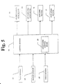
- Fig. 5 is a control block diagram for this apparatus.
- Each section of the photo-processing apparatus is controlled by a control section 80 having a microcomputer at its core.
- a conveyance control means 81 controls the driving conditions of the holding roller drive motor 29 and the nip conveyance drive motor 54 based on output signals from the first sensor 58, the second sensor 59 and the third sensor 60.
- the control section 80 also controls an operation of the exposing section 11 and the developing section 12.
- the conveyance control means 81 makes the holding roller drive motor 29 stop driving the holding rollers 40 and 41 while the holding rollers 40 and 41 nip the photo-sensitive material 10. After that, the conveyance control means 81 makes the nip conveying drive motor 54 start to raise the holder 30 while nipping the photo-sensitive material 10.
- the conveyance control means make the nip conveying drive motor 54 start driving to convey the holder 30 nipping the photo-sensitive material 10 with the holding rollers 40 and 41 in the vertical direction.
- the photo-sensitive material 10 is only raised while the guide holder 50 is guided with the guide bars 51 and 52.
- the photo-sensitive material begins to move in the lateral direction while the guide holder 50 is guided with the guide bars 51 and 52.
- the holder 30 is also guided by the guide bars 31 and 32 which are fixed to the guide holder 50 with the first guide bar holder 33.
- the photo-sensitive material 10 is also conveyed in the vertical direction while being conveyed in the lateral direction.
- the guide rollers 27 and 28 come to the position of the first straight portion 26c, the photo-sensitive material 10 is again only raised while the guide holder 50 is guided with the guide bars 51 and 52.
- the conveyance control means make the nip conveying motor 54 stop driving so as to convey the holder 30 nipping the photo-sensitive material 10 with the holding rollers 40 and 41.
- the edge of the photo-sensitive material 10 is transferred to the pair of rollers 62 by nipping the photo-sensitive material with the rollers 62 and 63 and a free rotation of the holding rollers 40 and 41. Therefore the photo-sensitive material has been conveyed from the outlet of the exposing section 11 to the inlet of the developing section which is located higher than and laterally offset from the outlet of the exposing section 11. After that, the photo-sensitive material 10 is developed in the developing section 12.
- the conveyance control means drives the nip conveying drive motor 54 in a reverse direction so that the holders 30 with the holding rollers 40 and 41 and so on are moved back to their initial position.
- the return to the initial position is detected by the second sensor 59 and the conveyance control means 81 stops the nip conveying driving motor 54 driving in the reverse direction.
- a second embodiment will now be explained with reference to Fig. 8.
- the basic construction of the exposing section 11 and the developing section 12 is similar to that of the first embodiment and the detailed description will be omitted and the same reference numerals and symbols are used as those in the first embodiment.
- the nip conveying drive motor 54 may be used as the power source for the lateral conveyance of the photo-sensitive material 10 by the configuration of the sprockets 55 and 56 as shown in Fig. 8.
- the guide rail 26 and the guide rollers 27 and 28 interlock the vertical guidance with the lateral conveyance and function as the guide mechanism for the vertical guidance as shown in Fig. 8.
- motors 29 and 54 are used as the power source in the above embodiments, other means like a cylinder may be used.
Landscapes
- Physics & Mathematics (AREA)
- General Physics & Mathematics (AREA)
- Photographic Processing Devices Using Wet Methods (AREA)
- Projection-Type Copiers In General (AREA)
- Discharge By Other Means (AREA)
Claims (9)
- Transporteur (13) pour un appareil de traitement photographique comprenant une première section de traitement (11) et une seconde section de traitement (12), comprenant une source d'alimentation en énergie (54) pour transporter un matériau photosensible (10) de ladite première section de traitement (11) jusqu'à ladite seconde section de traitement (12) le long d'un itinéraire de transport (26),
dans lequel ledit itinéraire de transport (26) est prolongé dans une direction verticale (Y) et une direction latérale (X),
caractérisé en ce que ledit transporteur (13)comprend en outre un mécanisme de guidage (26, 27, 28, 31, 32, 51, 52) comprenant un rail de guidage (26) ayant une portion oblique (26d) et un galet de guidage (27, 28) qui est guidé par ledit rail de guidage (26) et en ce que le galet de guidage (27, 28) est relié en rotation à un support (30) pour maintenir le matériau photosensible (10). - Transporteur pour un appareil de traitement photographique selon la revendication 1, dans lequel ladite source d'alimentation (54) transporte ledit matériau photosensible (10) dans ladite direction verticale (Y) et
dans lequel ledit mécanisme de guidage (26, 27, 28, 31, 32, 51, 52) guide ledit matériau photosensible transporté (10) avec ladite source d'alimentation (54) dans ladite direction latérale (X). - Transporteur pour un appareil de traitement photographique selon les revendications 1 et/ou 2, dans lequel ledit guidage latéral avec ledit mécanisme de guidage (26, 27, 28, 31, 32, 51, 52) est combiné avec ledit transport vertical avec ladite source d'alimentation (54).
- Transporteur pour un appareil de traitement photographique selon l'une ou plusieurs des revendications précédentes, dans lequel ladite source d'alimentation (54) transporte ledit matériau photosensible (10) dans ladite direction latérale (X) et dans lequel ladite source d'alimentation (54) et ledit mécanisme de guidage (26, 27, 28, 31, 32, 51, 52) guident ledit matériau photosensible transporté (10) dans ladite direction verticale (Y).
- Transporteur pour un appareil de traitement photographique selon l'une ou plusieurs des revendications précédentes, dans lequel ladite première section de traitement (11) est une section d'exposition pour imprimer une image sur un film photographique (8) sur ledit matériau photosensible (10) et ladite seconde section de traitement (12) est une section de développement pour développer ledit matériau photosensible exposé.
- Transporteur pour un appareil de traitement photographique selon la revendication 5, dans lequel une entrée de ladite section de développement (12) est déplacée plus haut qu'une sortie de ladite section d'exposition (11) et décalée latéralement de ladite sortie de ladite section d'exposition (11) au moyen d'un itinéraire de transport vers ladite section d'exposition.
- Transporteur pour un appareil de traitement photographique selon l'une ou plusieurs des revendications précédentes, comprenant en outre une paire de galets de pinçage (40, 41) pour pincer ledit matériau photosensible (10) et le support (30) supporte en rotation lesdits galets de pinçage (40, 41) et dans lequel ledit matériau photosensible (10) est transporté en étant pincé par lesdits galets de pinçage (40, 41).
- Transporteur pour un appareil de traitement photographique selon l'une ou plusieurs des revendications précédentes, dans lequel ledit mécanisme de guidage comprend en outre une première glissière (51, 52) pour faire coulisser verticalement ledit matériau photosensible (10), et une seconde glissière (31, 32) pour faire coulisser latéralement ledit matériau photosensible (10).
- Transporteur pour un appareil de traitement photographique selon la revendication 8, dans lequel ladite source d'alimentation (54) transporte ledit matériau photosensible (10) le long de ladite première glissière (51, 52).
Applications Claiming Priority (3)
| Application Number | Priority Date | Filing Date | Title |
|---|---|---|---|
| JP09370897A JP3663821B2 (ja) | 1997-04-11 | 1997-04-11 | 感光材料搬送装置 |
| JP93708/97 | 1997-04-11 | ||
| JP9370897 | 1997-04-11 |
Publications (2)
| Publication Number | Publication Date |
|---|---|
| EP0874270A1 EP0874270A1 (fr) | 1998-10-28 |
| EP0874270B1 true EP0874270B1 (fr) | 2002-09-18 |
Family
ID=14089923
Family Applications (1)
| Application Number | Title | Priority Date | Filing Date |
|---|---|---|---|
| EP98105890A Expired - Lifetime EP0874270B1 (fr) | 1997-04-11 | 1998-03-31 | Transporteur pour appareil de traitement photographique |
Country Status (4)
| Country | Link |
|---|---|
| US (1) | US6100959A (fr) |
| EP (1) | EP0874270B1 (fr) |
| JP (1) | JP3663821B2 (fr) |
| DE (1) | DE69807974T2 (fr) |
Families Citing this family (1)
| Publication number | Priority date | Publication date | Assignee | Title |
|---|---|---|---|---|
| CN2854646Y (zh) * | 2005-12-23 | 2007-01-03 | 上海多丽影像设备有限公司 | 一种大lcd微移动装置 |
Citations (1)
| Publication number | Priority date | Publication date | Assignee | Title |
|---|---|---|---|---|
| EP0854387A1 (fr) * | 1997-01-06 | 1998-07-22 | Noritsu Koki Co., Ltd. | Appareil de traitement d'un film |
Family Cites Families (12)
| Publication number | Priority date | Publication date | Assignee | Title |
|---|---|---|---|---|
| US4006395A (en) * | 1974-10-31 | 1977-02-01 | Eastman Kodak Company | Apparatus for the control of photosensitive material handling and cutting operations in computer output microfilmers |
| GB2103812B (en) * | 1981-08-01 | 1985-03-20 | Fotomec San Marco Spa | Conveying photosensitive material |
| ES2034366T3 (es) * | 1987-07-21 | 1993-04-01 | Gretag Aktiengesellschaft | Dispositivo para la realizacion de copias fotograficas. |
| JPS6453945A (en) * | 1987-08-21 | 1989-03-01 | Minolta Camera Kk | Conveying device for sheet type processed body |
| US4903100A (en) * | 1988-02-10 | 1990-02-20 | Fuji Photo Film Co., Ltd. | Long strip material handling apparatus |
| JP3191582B2 (ja) * | 1994-02-28 | 2001-07-23 | ノーリツ鋼機株式会社 | 写真処理装置の感光材料搬送方法及び装置 |
| JP2891116B2 (ja) * | 1994-10-14 | 1999-05-17 | ノーリツ鋼機株式会社 | 写真焼付処理方法 |
| US5735519A (en) * | 1995-02-09 | 1998-04-07 | Fuji Photo Film Co., Ltd. | Photosensitive-material conveying apparatus |
| JP3461967B2 (ja) * | 1995-03-13 | 2003-10-27 | 富士写真フイルム株式会社 | 記録媒体の処理方法及び記録媒体の処理装置 |
| JP3464562B2 (ja) * | 1995-03-13 | 2003-11-10 | 富士写真フイルム株式会社 | 記録媒体の処理方法及び記録媒体の処理装置 |
| JPH09236900A (ja) * | 1996-02-29 | 1997-09-09 | Fuji Photo Film Co Ltd | 感光材料処理装置 |
| JPH09301592A (ja) * | 1996-05-13 | 1997-11-25 | Riso Kagaku Corp | 画像形成システム |
-
1997
- 1997-04-11 JP JP09370897A patent/JP3663821B2/ja not_active Expired - Lifetime
-
1998
- 1998-03-31 EP EP98105890A patent/EP0874270B1/fr not_active Expired - Lifetime
- 1998-03-31 US US09/050,995 patent/US6100959A/en not_active Expired - Fee Related
- 1998-03-31 DE DE69807974T patent/DE69807974T2/de not_active Expired - Lifetime
Patent Citations (1)
| Publication number | Priority date | Publication date | Assignee | Title |
|---|---|---|---|---|
| EP0854387A1 (fr) * | 1997-01-06 | 1998-07-22 | Noritsu Koki Co., Ltd. | Appareil de traitement d'un film |
Also Published As
| Publication number | Publication date |
|---|---|
| EP0874270A1 (fr) | 1998-10-28 |
| JP3663821B2 (ja) | 2005-06-22 |
| DE69807974T2 (de) | 2003-08-07 |
| DE69807974D1 (de) | 2002-10-24 |
| JPH10279154A (ja) | 1998-10-20 |
| US6100959A (en) | 2000-08-08 |
Similar Documents
| Publication | Publication Date | Title |
|---|---|---|
| JP3170954B2 (ja) | 感光材料の現像処理方法及び装置 | |
| EP0874270B1 (fr) | Transporteur pour appareil de traitement photographique | |
| KR0178288B1 (ko) | 사진처리장치 | |
| EP0854387B1 (fr) | Appareil de traitement d'un film | |
| US4886352A (en) | Device for conveying photographic paper for use in photograph printing apparatus | |
| EP0645676A1 (fr) | Machine de développement photographique | |
| JP2002293463A (ja) | 画像記録装置の紙搬送機構 | |
| KR0169520B1 (ko) | 사진 처리기에서 필름으로부터 리더를 분리하는 방법 및 수단 | |
| JP3254500B2 (ja) | 画像形成装置 | |
| JPH07140627A (ja) | 写真処理装置 | |
| JPH0881091A (ja) | 画像形成装置 | |
| JP2606865B2 (ja) | 写真プリント装置 | |
| JP2942676B2 (ja) | 写真焼付装置用搬送制御装置 | |
| FI75544B (fi) | Foerfarande och anordning foer matning av dokument till en kopieringsmaskin. | |
| JP3054982B2 (ja) | 露光装置 | |
| JPH046033Y2 (fr) | ||
| JP2538110B2 (ja) | 原稿給送装置 | |
| CA2175901A1 (fr) | Installation de traitement de materiau photosensible | |
| JPH06230546A (ja) | 画像記録材料の搬送ガイド機構 | |
| JPH01234836A (ja) | 写真プリント装置 | |
| JPS6340133A (ja) | 焼付マスク駆動機構 | |
| JPH06183651A (ja) | 循環式自動原稿搬送装置 | |
| JPH0731358B2 (ja) | 写真焼付装置 | |
| JPH10319511A (ja) | フィルム搬送装置 | |
| JPH03297763A (ja) | シート状体の循環式供給装置 |
Legal Events
| Date | Code | Title | Description |
|---|---|---|---|
| PUAI | Public reference made under article 153(3) epc to a published international application that has entered the european phase |
Free format text: ORIGINAL CODE: 0009012 |
|
| AK | Designated contracting states |
Kind code of ref document: A1 Designated state(s): DE FR GB |
|
| AX | Request for extension of the european patent |
Free format text: AL;LT;LV;MK;RO;SI |
|
| 17P | Request for examination filed |
Effective date: 19981119 |
|
| AKX | Designation fees paid |
Free format text: DE FR GB |
|
| 17Q | First examination report despatched |
Effective date: 20010220 |
|
| GRAG | Despatch of communication of intention to grant |
Free format text: ORIGINAL CODE: EPIDOS AGRA |
|
| GRAG | Despatch of communication of intention to grant |
Free format text: ORIGINAL CODE: EPIDOS AGRA |
|
| GRAH | Despatch of communication of intention to grant a patent |
Free format text: ORIGINAL CODE: EPIDOS IGRA |
|
| GRAH | Despatch of communication of intention to grant a patent |
Free format text: ORIGINAL CODE: EPIDOS IGRA |
|
| GRAA | (expected) grant |
Free format text: ORIGINAL CODE: 0009210 |
|
| AK | Designated contracting states |
Kind code of ref document: B1 Designated state(s): DE FR GB |
|
| REG | Reference to a national code |
Ref country code: GB Ref legal event code: FG4D |
|
| REF | Corresponds to: |
Ref document number: 69807974 Country of ref document: DE Date of ref document: 20021024 |
|
| ET | Fr: translation filed | ||
| PLBE | No opposition filed within time limit |
Free format text: ORIGINAL CODE: 0009261 |
|
| STAA | Information on the status of an ep patent application or granted ep patent |
Free format text: STATUS: NO OPPOSITION FILED WITHIN TIME LIMIT |
|
| 26N | No opposition filed |
Effective date: 20030619 |
|
| PGFP | Annual fee paid to national office [announced via postgrant information from national office to epo] |
Ref country code: FR Payment date: 20050308 Year of fee payment: 8 |
|
| PGFP | Annual fee paid to national office [announced via postgrant information from national office to epo] |
Ref country code: GB Payment date: 20050330 Year of fee payment: 8 |
|
| PG25 | Lapsed in a contracting state [announced via postgrant information from national office to epo] |
Ref country code: GB Free format text: LAPSE BECAUSE OF NON-PAYMENT OF DUE FEES Effective date: 20060331 |
|
| GBPC | Gb: european patent ceased through non-payment of renewal fee |
Effective date: 20060331 |
|
| REG | Reference to a national code |
Ref country code: FR Ref legal event code: ST Effective date: 20061130 |
|
| PG25 | Lapsed in a contracting state [announced via postgrant information from national office to epo] |
Ref country code: FR Free format text: LAPSE BECAUSE OF NON-PAYMENT OF DUE FEES Effective date: 20060331 |
|
| PGFP | Annual fee paid to national office [announced via postgrant information from national office to epo] |
Ref country code: DE Payment date: 20100430 Year of fee payment: 13 |
|
| PG25 | Lapsed in a contracting state [announced via postgrant information from national office to epo] |
Ref country code: DE Free format text: LAPSE BECAUSE OF NON-PAYMENT OF DUE FEES Effective date: 20111001 |
|
| REG | Reference to a national code |
Ref country code: DE Ref legal event code: R119 Ref document number: 69807974 Country of ref document: DE Effective date: 20111001 |