EP0874607B1 - Attelle medicale et methode de fabrication de cette attelle - Google Patents
Attelle medicale et methode de fabrication de cette attelle Download PDFInfo
- Publication number
- EP0874607B1 EP0874607B1 EP96942221A EP96942221A EP0874607B1 EP 0874607 B1 EP0874607 B1 EP 0874607B1 EP 96942221 A EP96942221 A EP 96942221A EP 96942221 A EP96942221 A EP 96942221A EP 0874607 B1 EP0874607 B1 EP 0874607B1
- Authority
- EP
- European Patent Office
- Prior art keywords
- splint
- finger
- plate
- rail
- corrugations
- Prior art date
- Legal status (The legal status is an assumption and is not a legal conclusion. Google has not performed a legal analysis and makes no representation as to the accuracy of the status listed.)
- Expired - Lifetime
Links
- 238000004519 manufacturing process Methods 0.000 title claims description 8
- 238000000034 method Methods 0.000 title claims description 4
- 229910052751 metal Inorganic materials 0.000 claims abstract description 53
- 239000002184 metal Substances 0.000 claims abstract description 53
- 241001465754 Metazoa Species 0.000 claims abstract description 3
- 230000003100 immobilizing effect Effects 0.000 claims abstract 2
- 229910052782 aluminium Inorganic materials 0.000 claims description 8
- XAGFODPZIPBFFR-UHFFFAOYSA-N aluminium Chemical compound [Al] XAGFODPZIPBFFR-UHFFFAOYSA-N 0.000 claims description 8
- 239000006260 foam Substances 0.000 claims description 7
- 239000004698 Polyethylene Substances 0.000 claims description 5
- 229920005830 Polyurethane Foam Polymers 0.000 claims description 5
- 230000000737 periodic effect Effects 0.000 claims description 5
- -1 polyethylene Polymers 0.000 claims description 5
- 229920000573 polyethylene Polymers 0.000 claims description 5
- 239000011496 polyurethane foam Substances 0.000 claims description 5
- 230000002787 reinforcement Effects 0.000 claims description 5
- 238000007373 indentation Methods 0.000 claims description 3
- 230000002093 peripheral effect Effects 0.000 claims description 2
- 239000004411 aluminium Substances 0.000 claims 1
- 230000007423 decrease Effects 0.000 claims 1
- 239000006261 foam material Substances 0.000 claims 1
- 238000003825 pressing Methods 0.000 claims 1
- 210000003811 finger Anatomy 0.000 description 72
- 210000003813 thumb Anatomy 0.000 description 23
- 210000000707 wrist Anatomy 0.000 description 21
- 238000005452 bending Methods 0.000 description 19
- 210000003414 extremity Anatomy 0.000 description 18
- 210000000245 forearm Anatomy 0.000 description 13
- 239000004033 plastic Substances 0.000 description 6
- 229920003023 plastic Polymers 0.000 description 6
- 239000000463 material Substances 0.000 description 5
- 230000002349 favourable effect Effects 0.000 description 4
- 208000027418 Wounds and injury Diseases 0.000 description 3
- 239000003795 chemical substances by application Substances 0.000 description 2
- 230000006835 compression Effects 0.000 description 2
- 238000007906 compression Methods 0.000 description 2
- 230000006378 damage Effects 0.000 description 2
- 230000003247 decreasing effect Effects 0.000 description 2
- 230000000694 effects Effects 0.000 description 2
- 239000004744 fabric Substances 0.000 description 2
- 238000009499 grossing Methods 0.000 description 2
- 208000014674 injury Diseases 0.000 description 2
- 239000004753 textile Substances 0.000 description 2
- 240000007124 Brassica oleracea Species 0.000 description 1
- 235000003899 Brassica oleracea var acephala Nutrition 0.000 description 1
- 235000012905 Brassica oleracea var viridis Nutrition 0.000 description 1
- 241000282412 Homo Species 0.000 description 1
- 208000000491 Tendinopathy Diseases 0.000 description 1
- 206010043255 Tendonitis Diseases 0.000 description 1
- 230000006978 adaptation Effects 0.000 description 1
- 239000000853 adhesive Substances 0.000 description 1
- 230000001070 adhesive effect Effects 0.000 description 1
- 238000013459 approach Methods 0.000 description 1
- 210000000746 body region Anatomy 0.000 description 1
- 238000010276 construction Methods 0.000 description 1
- 230000001419 dependent effect Effects 0.000 description 1
- 239000003814 drug Substances 0.000 description 1
- 239000013013 elastic material Substances 0.000 description 1
- 239000010408 film Substances 0.000 description 1
- 230000035876 healing Effects 0.000 description 1
- 238000009413 insulation Methods 0.000 description 1
- 230000001788 irregular Effects 0.000 description 1
- 239000004922 lacquer Substances 0.000 description 1
- 239000011505 plaster Substances 0.000 description 1
- 239000002985 plastic film Substances 0.000 description 1
- 229920006255 plastic film Polymers 0.000 description 1
- 239000002984 plastic foam Substances 0.000 description 1
- 238000009751 slip forming Methods 0.000 description 1
- 238000001356 surgical procedure Methods 0.000 description 1
- 201000004415 tendinitis Diseases 0.000 description 1
Images




Classifications
-
- A—HUMAN NECESSITIES
- A61—MEDICAL OR VETERINARY SCIENCE; HYGIENE
- A61F—FILTERS IMPLANTABLE INTO BLOOD VESSELS; PROSTHESES; DEVICES PROVIDING PATENCY TO, OR PREVENTING COLLAPSING OF, TUBULAR STRUCTURES OF THE BODY, e.g. STENTS; ORTHOPAEDIC, NURSING OR CONTRACEPTIVE DEVICES; FOMENTATION; TREATMENT OR PROTECTION OF EYES OR EARS; BANDAGES, DRESSINGS OR ABSORBENT PADS; FIRST-AID KITS
- A61F5/00—Orthopaedic methods or devices for non-surgical treatment of bones or joints; Nursing devices ; Anti-rape devices
- A61F5/01—Orthopaedic devices, e.g. long-term immobilising or pressure directing devices for treating broken or deformed bones such as splints, casts or braces
- A61F5/04—Devices for stretching or reducing fractured limbs; Devices for distractions; Splints
- A61F5/05—Devices for stretching or reducing fractured limbs; Devices for distractions; Splints for immobilising
- A61F5/058—Splints
- A61F5/05841—Splints for the limbs
- A61F5/05858—Splints for the limbs for the arms
- A61F5/05866—Splints for the limbs for the arms for wrists, hands, fingers or thumbs
-
- A—HUMAN NECESSITIES
- A61—MEDICAL OR VETERINARY SCIENCE; HYGIENE
- A61F—FILTERS IMPLANTABLE INTO BLOOD VESSELS; PROSTHESES; DEVICES PROVIDING PATENCY TO, OR PREVENTING COLLAPSING OF, TUBULAR STRUCTURES OF THE BODY, e.g. STENTS; ORTHOPAEDIC, NURSING OR CONTRACEPTIVE DEVICES; FOMENTATION; TREATMENT OR PROTECTION OF EYES OR EARS; BANDAGES, DRESSINGS OR ABSORBENT PADS; FIRST-AID KITS
- A61F5/00—Orthopaedic methods or devices for non-surgical treatment of bones or joints; Nursing devices ; Anti-rape devices
- A61F5/01—Orthopaedic devices, e.g. long-term immobilising or pressure directing devices for treating broken or deformed bones such as splints, casts or braces
- A61F5/04—Devices for stretching or reducing fractured limbs; Devices for distractions; Splints
- A61F5/05—Devices for stretching or reducing fractured limbs; Devices for distractions; Splints for immobilising
- A61F5/058—Splints
- A61F5/05816—Inflatable splints
-
- A—HUMAN NECESSITIES
- A61—MEDICAL OR VETERINARY SCIENCE; HYGIENE
- A61F—FILTERS IMPLANTABLE INTO BLOOD VESSELS; PROSTHESES; DEVICES PROVIDING PATENCY TO, OR PREVENTING COLLAPSING OF, TUBULAR STRUCTURES OF THE BODY, e.g. STENTS; ORTHOPAEDIC, NURSING OR CONTRACEPTIVE DEVICES; FOMENTATION; TREATMENT OR PROTECTION OF EYES OR EARS; BANDAGES, DRESSINGS OR ABSORBENT PADS; FIRST-AID KITS
- A61F5/00—Orthopaedic methods or devices for non-surgical treatment of bones or joints; Nursing devices ; Anti-rape devices
- A61F5/01—Orthopaedic devices, e.g. long-term immobilising or pressure directing devices for treating broken or deformed bones such as splints, casts or braces
- A61F5/04—Devices for stretching or reducing fractured limbs; Devices for distractions; Splints
- A61F5/05—Devices for stretching or reducing fractured limbs; Devices for distractions; Splints for immobilising
- A61F5/058—Splints
- A61F5/05825—Strips of substantially planar form
Definitions
- the present invention relates to the field of medical Splints for human but also for veterinary medicine. It relates to a medical splint for fixation or immobilization of moving body parts according to Preamble of claim 1 and a method for their Production.
- Metal rails are not uncommon. Such a rail is e.g. known from US-A-3,943,923.
- Rails which essentially consist of an easily plastically deformable Metal sheet (usually made of Al), which one or with a cover layer made of plastic foam on both sides or the like. are covered from the prior art known in many variants.
- the rails are usually as even plates, which in the application are plastic Bending to a limited extent to the Limbs that seemed to be adjusted to fit through concerns to give the necessary hold or the necessary fixation to enable.
- the inner metal sheet can either practically fill the entire surface of the rail, as in US-A-3,943,923, US-A-4,676,233 or EP-B1-0 039 323 is the case, or it is in shape several stiffening metal strips embedded in the rail, as is the case with EP-B1-0 073 772.
- the rail should be sufficiently plastic be deformable or bendable so that they can be handled by hand to the limbs to be fixed without additional aids (Body parts) can be adjusted.
- the splint is sufficient be stiff in order to fix the required limbs guarantee.
- One rail is known from US-A-3,850,167, in which two Corrugated cardboard with its corrugations oriented orthogonally to each other glued together in a predetermined U-shape to create a mechanically rigid rail.
- the task is characterized by the totality of the characteristics Claims 1, 23 and 24 solved.
- the essence of the invention is through the corrugation of the Sheet metal has an easy stretch and compressibility in to generate the rail level, so that the rail without big difficulties local unevenness on the to be fixed Limbs or body parts can be adjusted. Is a If local expansion is required, the waves pull through the metal sheet apart in this area. In contrast, is a lo kale compression necessary, the waves in this throw Area steeper and closer together. To this In this way, the rail gets an exceptionally high local Deformability.
- Another important feature of the invention Rail is transverse to the orientation of the waves to the rail axis. If the rail with the rail axis parallel to the limbs to be fixed (body parts) and the splint to adapt to the limbs across the rail axis e.g.
- the rail in that the sheet metal is made of aluminum the metal sheet has a thickness of less than or equal to 1 mm, preferably less than or equal to 0.3 mm, the waves a periodic distance between each other of between 1 mm and 8 mm, in particular about 3-5 mm, and the waves a height between the wave crests and wave valleys of between 0.5 mm and 5 mm, in particular between 1 mm and 3 mm, exhibit.
- a first preferred embodiment of the invention Rail is characterized in that the metal sheet over the entire surface is corrugated, and the waves transverse to the rail axis between opposite edges of the metal sheet are continuously formed. hereby the rail can be flexibly used for the most different Use splinting.
- the cover cover layers comprises, which are made of a plastic, in particular from a foam, preferably from an elastic Polyethylene or polyurethane foam exist, for example has a layer thickness of 1 to 3 mm.
- upholstery can also be much thicker (e.g. in the cm range).
- one of the cover layers can be used or both cover layers on the outside additionally be laminated with a layer of textile.
- the metal sheet can be easily and safely between the Embed cover layers if according to another preferred one Embodiment the cover layers over the edge of the Metal sheets protrude and a peripheral edge area form in which the two cover layers together connected, preferably glued or welded.
- the rail according to another embodiment has an essentially rectangular edge contour.
- Rail is characterized in that at one point or several points of the rail means for detachable or permanent connection of the rail with additional fasteners are provided. This allows the rail to the adaptation to the limbs easily and flexibly using additional fasteners such as Additional straps be fixed and secured.
- the splint according to the invention can preferably be used in humans as a forearm or wrist splint / support, as a thumb splint, as a finger splint, or as a leg and / or foot splint be used.
- a preferred embodiment of the invention Splint in the form of a finger splint for the fixation of a single injured finger or multiple injured fingers, is characterized in that the metal sheet has an elongated, bordered in the longitudinal direction by two longitudinal edges Panel is that the panel is bordered by the long edges Has side sections, which out of the plate level can be bent to the side walls in the finger splint to give stored fingers to the side and at the same time a contribution to the longitudinal stiffness of the finger splint to afford, and that in the side sections a A plurality of shafts are provided in the plate are, which extend transversely into the Extend side sections or side walls.
- Fig. 1 is a preferred embodiment of an inventive Rail in generally applicable rectangular Shown form.
- 1A shows the rail in perspective View.
- 1B shows the longitudinal section through the rail along the line B-B in Fig. 1A.
- the rail 1 has an elongated, rectangular in this embodiment Shape with preferably rounded corners.
- the rail 1 is a thin metal sheet 2 made of aluminum, which is consistently with a fine corrugation (waves 42 in the cut-open area 41 in FIG. 1A).
- the outer dimensions of the rail 1 can vary widely his. Suitable as a general forearm splint, for example a rail 1 with a width of 10-20 cm and a length of 20 - 30 cm.
- the corrugation of the metal sheet 2 is compared to the outer Dimensions very small:
- the periodic distance P of the waves 42 is between 1 mm and 8 mm and is in particular about 3-5 mm.
- the Waves 42 have a height between the wave crests and wave troughs from also between 1 mm and 8 mm, in particular between 2 mm and 5 mm, on.
- the metal sheet 2 made of aluminum has a thickness of less than or equal to 1 mm, preferably less than or equal to 0.3 mm.
- the Corrugation of the metal sheet 2 can be generated for example be that a flat metal sheet opposed by two rotating, intermeshing gear rollers pulled or pressed between two corrugated stamps becomes.
- the corrugated metal sheet 2 itself could Rail are used.
- A can be used as a covering layer Fabric, a felt or the like can be used.
- the cover layers 3, 4 consist of a plastic, in particular a foam, preferably from a elastic polyethylene or polyurethane foam with a Thickness of a few millimeters, which is flexible, elastic and is hygienically safe. As can be seen from Fig. 1B, the cover layers 3, 4 protrude over the edge of the metal sheet 2 beyond.
- the rail 1 is used with the rail axis 6 parallel to the limbs (arm or the like) or body parts (Neck, trunk) and bent across the rail axis U-shaped for the limbs (body parts) and molded (see also Fig. 4, 4A).
- the rail must do this not necessarily as a flat plate, but can already be pre-shaped to facilitate use and to rule out incorrect orientation during use.
- the corrugation of the metal sheet 2 enables a local compression or elongation in a simple manner the level of the metal sheet 2, so that the rail also on very irregularly shaped limbs (body parts) can be easily adjusted by bending by hand.
- the special orientation of the from one edge ensures of the metal sheet 2 to the other edge transversely to the rail axis 6 through waves 42 surprisingly that the Rail 1 has an unusually high rigidity after bending has, although initially in the unbent state is very flexible.
- a local increase the rigidity can be brought about by the fact that the Waves in this area with your thumb or otherwise be flattened out or pressed out of the sheet.
- rails can still be easily modeled, see above that they also cover the body parts or limbs at all times can be adjusted again.
- the rail can be molded with additional Fasteners such as a strap (Fig. 2B) or the like on the splinted limbs (body parts) be fastened to ensure that the rail does not fall off.
- additional Fasteners such as a strap (Fig. 2B) or the like on the splinted limbs (body parts) be fastened to ensure that the rail does not fall off.
- the rail 1 e.g. in corner areas
- the connection means come 1A, for example, push buttons or push button parts 7 or 8 eyes. But it is also conceivable for others Lanyards such as Adhesive surfaces or Velcro connectors or hooks. If eyelets 8 are used, this in the rail plane through the layer sequence from the bottom Cover layer 4, sheet metal 2 and top cover layer 3 attached through.
- push buttons are preferred or push button parts 7, each only through the metal sheet 2 and one of the cover layers 3, 4 go through on the However, the back is covered by the other cover layer are.
- the push buttons have the particular advantage that they a rotation of the fasteners after connecting with enable the rail. In this way, the fasteners optimally attached to the splinted body part.
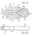
- FIG. 2A A second, very special embodiment in the form of a Finger splint (metacarpal splint) is shown in Fig. 2A.
- the rail 9 consists of several one below the other connected sub-areas, namely a tapering towards the front Finger part 10, on the back to the side two tongue-like support parts 11 and 12 in the middle Connect support plate 13.
- the rail 9 is like that Rail 1 as a sequence of layers from the lower cover layer, corrugated Metal sheet and top cover layer built up.
- the Corrugation of the metal sheet is shown by dashed lines parallel lines indicated.
- the shafts 15 run transversely to the rail axis 45 the rail in the above Way in the direction of arrows 43 and 44 U-shaped to shine on a lying on the rail 9 Finger 28 (shown in dashed lines) are bent.
- the shafts 15 in particular enable the finger part 10 after bending in the direction of the rail axis 45 can be curved so that the splinted finger 28 in one preferred curved position is fixed.
- the finger part 10 can - as shown in Fig. 2A - in front of the fingertip end up; but it can also be longer than that to shining fingers.
- the other push button part 14a as a counterpart is in the center the support plate 13 arranged. If the rail 9 in the Palm positioned and in the finger part 10 to the shining finger 28 is formed, the strap 17 (or the above Intermediate piece with subsequent belt) with the Snap button part 14b snaps into snap button part 14a pressed in and the strap 17 wrapped around the hand several times and e.g. fixed with tape or the usual hook. The rail 9 is securely fixed on the hand in this way.
- FIG. 3 shows a rail 19 with special (non-rectangular) Edge contour, which is especially used as a thumb splint.
- the splint 19 in this case comprises a wide wrist part 20 and a subsequent narrower and tapered thumb part 21. But the splint can also be shorter and without a wrist part and serves then as a pure metacarpal thumb splint, in which the wrist is free to move.
- the inner structure of the rail 19 is the same as for the rail 1 from Fig. 1.
- the (from the outside because of the covering layers) waves 22 in the metal sheet are indicated by the parallel dashed lines. In this case, the shafts 22 are continuously transverse arranged to the rail axis 46.
- the rail 19 is - as in 3 shown - laterally on the hand 24 to be shone applied so that the thumb part 21 with the rail axis 46 is parallel to the thumb 25.
- the thumb part 21 can thereby - as shown in Fig. 3 - release the thumb tip; he can but also completely cover the thumb 25 lengthways.
- the rail 19 is then in the direction of the arrows 26a, and 27a, b are bent over and molded onto the hand 24 accordingly.
- the thumb 25 is then fixed in relation to the hand 24, so that the root of the thumb is immobilized.
- By a Extension of the rail 19 to the forearm can additionally fixation (immobilization) of the wrist can be achieved. It can also be advantageous in certain areas the rail 19 (see also FIG.
- a reinforcement 53 e.g. in the form of a parallel to the rail axis 46 Sheet metal strip to embed.
- the reinforcement then ensures adjusting the splint 19 to the thumb 25 for one more further improved fixation.
- the rail 19 are on hand in the area of the rail 19, the between Thumb 25 and index finger come to rest, again lanyard in the form of a recessed push button part 23 provided in which e.g. a belt according to Fig. 2B (or a corresponding intermediate piece) can be snapped in.
- FIG. 4 Another application is that shown in FIG. 4 Splinting of the forearm or support of the wrist as they do for example in the case of tendonitis or Surgery may be necessary.
- the rail 29 in this is placed on the forearm 34 in the manner shown that it protrudes beyond the wrist 35 and the base of the fingers, but mostly leaves the fingers themselves free.
- the Splint is then in the direction of arrows 39, 40 around the forearm 34, the wrist 35 and the hand 33 bent around in a U-shape, the ones running transversely to the rail axis 30 Shafts 36 in the sheet metal of the rail for formability and stiffen the rail.
- a push button 31 or the like is provided here as a connecting means in which a belt according to FIG. 2B or a Support part 32 can be snapped.
- a support part 32 comes in particular a small rail considering the same construction with a corrugated Has sheet metal, like rail 29, and through the gusset hook-shaped between thumb 37 and index finger 38 is bent over and thus fixes the rail 29 on the hand 33.
- the rail 29 can also by a buttoned and tape wrapped several times around the arm as shown in FIG. 2B become
- a strap can be attached as shown in FIG. 2B.
- support part 32 As good as but it is also conceivable to support part 32 as a molded, laterally protruding extension of the rail 29 train so that the rail is attached to the hand 33 without push button and without additional, separate fastening means can be done.
- the same principle (the molded one Extension) can of course also be related can be applied with the thumb splint according to FIG. 3.
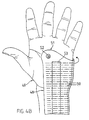
- FIG. 4B Splint 48 in the form of a shortened forearm or Wrist support.
- the rail 48 essentially has one rectangular shape with transverse waves 50 and one molded "ear" 51, in which a push button 52 as a fastener e.g. arranged for a band according to FIG. 2B is.
- the rail 48 is in the manner shown (arrow) U-shaped around the wrist of the hand 49, so that Wrist is fixed, but the fingers are free to move can.
- the rail 48 can then with a buttoned tape 2B, which is first between between thumb and Index finger passed and then several times around that splinted splinted wrist is fixed on the wrist become.
- the invention results in a rail which easily deformable and to the limbs to be shone or Body parts is customizable, despite the high stiffness (after the deformation) has a surprisingly high deformability, and flexibly adaptable to different applications is.
- Applications as are particularly favorable Arm, hand or finger splint. But they are also the same Use as a splint in the leg or foot area or in others Human body regions (neck, spine, etc.), but also possible with animals.
- FIG. 5 is an embodiment of a side view Splint according to the invention in the form of a finger splint played.
- the finger splint is for reasons of clarity the usual cover with an elastic Material, e.g. a layer of polyethylene or Polyurethane foam, omitted.
- the finger splint 118 out Fig. 5 consists essentially of the length of a Fingers 125 customizable elongated plate 119 made of aluminum sheet or film that is trough-shaped in the longitudinal direction has been. The bending created two side walls 120 and 121, the finger to be fixed 125, the on the plate 119 rests in a central area to give lateral support and at the same time a longitudinal stiffness of the finger splint to lend.
- the initially straight rail is then usually curved to fix it of the finger 125 in a relaxed, curved position (so-called "physiological position").
- the curvature takes place in such a way that in the area of the longitudinal edges 122, 123 Plate 119, which is also the side walls 120, 121 upwards limit, an elongation in the longitudinal direction takes place.
- stretching agents in the Plate 119 of the finger splint 118 shafts 124 are provided
- the finger splint 139 from FIG. 6A consists essentially of one through longitudinal edges 145, 146 and transverse edges 147, 148 delimited plate 140, which by a corresponding cover 151 is enclosed.
- bending lines 143, 144 divide side portions 141, 142 that bent as side walls of the rail out of the plate level should be to ensure the longitudinal stability and the To give fingers or fingers lateral support.
- shafts 150 in this exemplary embodiment provided transversely to the longitudinal direction of the plate 140 of one longitudinal edge 145 to the other longitudinal edge 146 and in Fig. 6A by dotted and dash-dotted lines are indicated.
- the plate 140 faces forward in this example decreasing width, that of the slimmer towards the tip Finger shape takes into account and causes the bent Side walls (120, 121 in Fig. 5) despite the changing finger thickness maintain an approximately constant height can.
- the width can also be chosen to be constant, to e.g. a simplified handling of the plate in the To achieve manufacture.
- the plate 140 is at the corners preferably rounded to reduce the risk of injury.
- the plate 140 is further covered by a cover 151 covered a all-round "pocket" for the Plate 140 forms and in Fig. 6 by a dashed line is indicated.
- Such a cover in the form of an elastic Foam layer is e.g. in US-A-4,676,233 described in detail, so here on a closer Explanation can be omitted.
- other materials such as Plastic films, lacquers or textile materials are suitable as a cover are.
- FIG. 6B The longitudinal section through the finger splint 139 along the line X-X in FIG. 6A is shown in FIG. 6B and shows that the plate 140 is preferably continuous in the longitudinal direction corrugated plate is formed, the waves 150th a period P and a height h (between Wellenberg and Wave trough). Because the shafts 150 stiffen the Effect plate 140 in the transverse direction and thus a bending of the side sections 141, 142 must complicate in principle Material and thickness of the plate 140 and the geometry of the Shafts can be chosen to fit the finger splint To make the insert sufficiently easily deformable.
- the plate 140 is made of aluminum, if the plate 140 has a thickness of less than or equal to 0.5 mm, preferably less than or equal to 0.2 mm when the waves a periodic distance P from each other of a few millimeters, preferably between 0.5 mm and 5 mm, in particular about 2-3 mm, and if the waves have a height h of a few millimeters, preferably between 0.5 mm and 5 mm, preferably between 1 mm and 3 mm.
- Aluminum plates or sheets with a thickness of about 0.2 mm or less ensure good formability and simultaneous stability of the finger splint.
- a finger splint according to FIG. 6 with a corrugated plate bent in a trough shape and then curved in the longitudinal direction 5 results.
- the finger splint 118 encloses the corrugated plate 119 the finger 125 with the side walls 120 and 121.
- the curvature of the rail in the longitudinal direction creates the longitudinal edges 122 and 123 of the plate 119 have a strong tensile stress, which the waves 124 in the region of the longitudinal edges decreasing towards the inside "smoothes out” so that at extreme Curvature the waves on the longitudinal edges 122, 123 completely have disappeared and the straight lines shown in FIG Form longitudinal edges.
- the finger splints are of the type shown in FIGS. 5 and 6 conveniently kept in the unbent state, so that they are easily packaged (similar to wound plasters or the like) and can be stored. Basically, it is conceivable for different finger sizes also different rail sizes ready injury. However, it turned out that all essential use cases with a standard size can be covered as long as a single finger is splinted. With such a standard size, the Plate 119, 140 a maximum width between 4 cm and 10 cm, preferably about 6 cm, and a maximum length between 6 cm and 14 cm, preferably about 10 cm. Protruding areas the rail can be bent back.
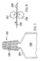
- the panels must be wide be chosen accordingly larger. It is also conceivable that - as shown in Fig. 7 - the finger splint 152 integral part of a longer and wider bracer 153 is, and is formed on the front end of the arm splint 153. This allows the finger base to be injured Fix fingers relative to the hand or arm so that one undisturbed healing is also possible in this case.
- the rails 152 and 153 are padded a cover 154 as appropriate.
- the finger splint with a corrugated plate according to FIGS. 5, 6 and 7 can be manufactured in different ways. Especially production is simple, in which - as can be seen from FIG. 8 a flat plate 156 for generating the waves 159 between two meshing gears 157, 158 or tooth rollers is passed in the direction of the arrow.
- the finished corrugated plate can then be coated with the desired one Cover.
- the cover can also be applied before the curl.
- the teeth the gears 157, 158 can have different shapes.
- it is advantageous if the waves 159 generated are one form evenly curved wavy line to create notch effects to avoid breaking into the plate when bending the plate, and the "smoothing" of the waves to ease when curling the finger splint.
- plate can also be used on different other types are curled.
- the plate for generating the waves between accordingly to press corrugated dies either have flat stamp surfaces and perpendicular to each other are pressed, or have arcuate stamp surfaces and roll together.
- the printing stamp can be designed in such a way that they Take over the cutting function and the rail with the desired Provide edge contour.
Landscapes
- Health & Medical Sciences (AREA)
- Animal Behavior & Ethology (AREA)
- Public Health (AREA)
- Engineering & Computer Science (AREA)
- Biomedical Technology (AREA)
- Heart & Thoracic Surgery (AREA)
- Vascular Medicine (AREA)
- Life Sciences & Earth Sciences (AREA)
- Nursing (AREA)
- Orthopedic Medicine & Surgery (AREA)
- Veterinary Medicine (AREA)
- General Health & Medical Sciences (AREA)
- Orthopedics, Nursing, And Contraception (AREA)
- Materials For Medical Uses (AREA)
- Surgical Instruments (AREA)
- Physical Vapour Deposition (AREA)
- Laminated Bodies (AREA)
- Prostheses (AREA)
Claims (25)
- Attelle médicale (1, 9, 19, 29, 48, 118, 139, 152) pour la fixation ou l'immobilisation de parties corporelles mobiles, en particulier des membres d'une personne ou d'un animal, le long d'un axe d'attelle (6, 30), laquelle attelle (1, 9, 19, 29, 48, 118, 139, 152) comprend une feuille métallique (2 ; 119, 140) pouvant être déformable plastiquement à la main sans auxiliaire supplémentaire, laquelle se compose d'aluminium, présente une épaisseur inférieure ou égale à 1 mm, de préférence inférieure à 0,3 mm, est réalisée avec une ondulation au moins dans des régions partielles et est recouverte des deux côtés d'un revêtement (3, 4 ; 151, 154), caractérisée en ce que les sommets et les vallées des ondulations (15, 22, 36, 42, 50, 124, 150, 155, 159) s'étendent essentiellement transversalement à l'axe de l'attelle (6, 30), en ce que les ondulations (15, 22, 36, 42, 50 ; 124, 150, 155, 159) présentent entre elles une distance périodique (P) comprise entre 1 mm et 8 mm, en particulier environ entre 3 et 5 mm, et en ce que les ondulations (15, 22, 36, 42, 50 ; 124, 150, 155, 159) présentent une hauteur entre les sommets des ondulations et les vallées des ondulations comprise entre 1 mm et 8 mm, en particulier entre 2 mm et 5 mm.
- Attelle selon la revendication 1, caractérisée en ce que la feuille métallique (2) est réalisée avec une ondulation sur toute la surface, et les ondulations (15, 22, 36, 42, 50) sont réalisées de manière continue transversalement à l'axe de l'attelle (6, 30) entre des bords opposés de la feuille métallique (2).
- Attelle selon l'une quelconque des revendications 1 ou 2, caractérisée en ce que le revêtement comprend des couches de revêtement (3, 4) qui se composent d'une matière plastique, en particulier d'une mousse, de préférence d'une mousse de polyéthylène ou de polyuréthanne élastique.
- Attelle selon la revendication 3, caractérisée en ce que les couches de revêtement (3, 4) dépassent au-delà du bord de la feuille métallique (2) et forme une région de bord périphérique (5) dans laquelle les deux couches de revêtement (3, 4) sont connectées l'une à l'autre, de préférence par collage ou par soudage.
- Attelle selon l'une quelconque des revendications 1 à 4, caractérisée en ce que l'attelle (1, 29) présente un contour essentiellement rectangulaire.
- Attelle selon l'une quelconque des revendications 1 à 4, caractérisée en ce que l'attelle (9, 19, 48) est adaptée par son contour périphérique à la région d'utilisation respective de telle sorte qu'une avancée saillant latéralement soit formé sur l'attelle afin de fixer l'attelle aux membres ou aux parties du corps à atteler.
- Attelle selon l'une quelconque des revendications 1 à 6, caractérisée en ce que des moyens (7, 8, 14a, 23, 31, 52) pour l'assemblage desserrable ou durable de l'attelle (1, 9, 19, 29, 48) à des moyens de fixation supplémentaires (17, 32) sont prévus en un endroit ou en plusieurs endroits de l'attelle (1, 9, 19, 29, 48).
- Attelle selon la revendication 7, caractérisée en ce que les moyens d'assemblage comprennent un bouton pression (31, 52) ou une partie de bouton pression (7, 14a, 23) disposé(e) dans le plan de l'attelle.
- Attelle selon la revendication 8, caractérisée en ce que le bouton pression (31, 52) ou la partie de bouton pression (7, 14a, 23) est recouvert(e) au dos par la couche de revêtement (3, respectivement 4) qui s'y trouve.
- Attelle selon la revendication 7, caractérisée en ce que les moyens d'assemblage comprennent un oeillet (8) prévu dans le plan de l'attelle.
- Attelle selon la revendication 7, caractérisée en ce que les moyens d'assemblage comprennent une attache par bandes agrippantes.
- Attelle selon l'une quelconque des revendications 1 à 11, caractérisée en ce que l'on prévoit, dans des régions prédéterminées de l'attelle (48), un renforcement supplémentaire (53), en particulier sous la forme d'un ruban de feuille métallique posé ou d'une plaque en feuille métallique.
- Attelle selon la revendication 1, sous la forme d'une attelle pour un doigt (118, 139, 152) pour la fixation d'un seul doigt blessé (125) ou de plusieurs doigts blessés, caractérisée en ce que la feuille métallique est une plaque longue (119, 140), bordée dans la direction longitudinale par deux arêtes longitudinales (122, 123 ; 145, 146), en ce que la plaque (119, 140) présente des portions latérales bordées par les arêtes longitudinales (122, 123 ; 145, 146), lesquelles peuvent être repliées hors du plan de la plaque, afin de fournir un support latéral sous forme de parois latérales (120, 121) pour le doigt (125) placé dans l'attelle pour doigt (118, 139, 152) et pour assurer simultanément une contribution à la rigidité longitudinale de l'attelle pour doigt, et en ce que l'on prévoit dans les portions latérales (141, 142) une pluralité d'ondulations (124, 150, 155, 159) prévues dans la plaque (119, 140, 156), lesquelles s'étendent depuis les arêtes longitudinales (122, 123 ; 145, 146) transversalement vers l'intérieur dans les portions latérales (141, 142) ou les parois latérales (120, 121).
- Attelle pour doigt selon la revendication 13, caractérisée en ce que les ondulations (124, 150, 155, 159) sont réalisées sous la forme d'ondulations continues entre les deux arêtes longitudinales (122, 123, respectivement 145, 146) .
- Attelle pour doigt selon la revendication 14, caractérisée en ce que la plaque (119, 140) est réalisée au moins partiellement en tant que plaque ondulée de manière continue dans la direction longitudinale.
- Attelle pour doigt selon la revendication 15, caractérisée en ce que la plaque (119, 140) présente une épaisseur inférieure ou égale à 0,5 mm, de préférence inférieure ou égale à 0,2 mm en ce que les ondulations (124, 150, 155, 159) présentent entre elles une distance périodique (P) comprise entre 0,5 mm et 5 mm, en particulier environ entre 2 et 3 mm, et en ce que les ondulations (124, 150, 155, 159) présente une hauteur (h) entre les sommets des ondulations et les vallées des ondulations comprise entre 0,5 mm et 5 mm, de préférence entre 1 mm et 3 mm.
- Attelle pour doigt selon l'une quelconque des revendications 13 à 16, caractérisée en ce que la plaque (119, 140) de l'attelle pour doigt (118, 139, 152) présente une largeur se réduisant vers l'avant.
- Attelle pour doigt selon l'une quelconque des revendications 13 à 16, caractérisée en ce que la plaque de l'attelle pour doigt présente une largeur constante.
- Attelle pour doigt selon l'une quelconque des revendications 17 ou 18, caractérisée en ce que la plaque (119, 140) présente une largeur maximale comprise entre 4 cm et 10 cm, de préférence d'environ 6 cm, et une longueur maximale comprise entre 6 cm et 14 cm, de préférence d'environ 10 cm.
- Attelle pour doigt selon l'une quelconque des revendications 13 à 19, caractérisée en ce que la plaque (119, 140) est limitée derrière par une arête transversale arrière (148) et présente un renfoncement (149) dans la région de l'arête transversale arrière (148).
- Attelle pour doigt selon l'une quelconque des revendications 13 à 20, caractérisée en ce que le revêtement (151, 154) se compose d'une mousse, de préférence d'une mousse élastique de polyéthylène ou de polyuréthanne.
- Attelle pour doigt selon l'une quelconque des revendications 13 à 21, caractérisée en ce que l'attelle pour doigt (152) fait partie d'une attelle de bras (153) plus longue et plus large, et est formée à l'extrémité avant de l'attelle pour bras (153).
- Procédé de fabrication d'une attelle pour doigt selon la revendication 13, caractérisé en ce qu'une plaque plane (156) est introduite entre deux roues dentées s'engrenant (157, 158) ou deux cylindres dentés s'engrenant afin de produire les ondulations (59).
- Procédé de fabrication d'une attelle pour doigt selon la revendication 13, caractérisé en ce qu'une plaque plane est pressée entre deux matrices de pression ondulées correspondantes pour produire les ondulations.
- Procédé selon la revendication 24, caractérisé en ce que le contour du bord de l'attelle pour doigt est estampé ou découpé simultanément au pressage.
Applications Claiming Priority (7)
| Application Number | Priority Date | Filing Date | Title |
|---|---|---|---|
| CH360595 | 1995-12-20 | ||
| CH3605/95 | 1995-12-20 | ||
| CH03605/95A CH689820A5 (de) | 1995-12-20 | 1995-12-20 | Fingerschiene sowie Verfahren zur Herstellung derselben. |
| CH1950/96 | 1996-08-08 | ||
| CH195096 | 1996-08-08 | ||
| CH195096 | 1996-08-08 | ||
| PCT/CH1996/000450 WO1997022312A1 (fr) | 1995-12-20 | 1996-12-19 | Attelle medicale, tole metallique utilisee pour former cette attelle et utilisation de cette attelle |
Publications (2)
| Publication Number | Publication Date |
|---|---|
| EP0874607A1 EP0874607A1 (fr) | 1998-11-04 |
| EP0874607B1 true EP0874607B1 (fr) | 2003-11-26 |
Family
ID=25689079
Family Applications (1)
| Application Number | Title | Priority Date | Filing Date |
|---|---|---|---|
| EP96942221A Expired - Lifetime EP0874607B1 (fr) | 1995-12-20 | 1996-12-19 | Attelle medicale et methode de fabrication de cette attelle |
Country Status (19)
| Country | Link |
|---|---|
| US (1) | US6039706A (fr) |
| EP (1) | EP0874607B1 (fr) |
| JP (1) | JP4439018B2 (fr) |
| KR (1) | KR100489848B1 (fr) |
| CN (1) | CN1222256C (fr) |
| AT (1) | ATE254898T1 (fr) |
| AU (1) | AU710147B2 (fr) |
| BR (1) | BR9612195A (fr) |
| CA (1) | CA2239085C (fr) |
| CZ (1) | CZ293432B6 (fr) |
| DE (2) | DE59610838D1 (fr) |
| ES (1) | ES2211997T3 (fr) |
| HU (1) | HU220982B1 (fr) |
| IL (1) | IL124666A (fr) |
| MX (1) | MX9804944A (fr) |
| PL (1) | PL184055B1 (fr) |
| PT (1) | PT874607E (fr) |
| TR (1) | TR199801141T2 (fr) |
| WO (1) | WO1997022312A1 (fr) |
Cited By (2)
| Publication number | Priority date | Publication date | Assignee | Title |
|---|---|---|---|---|
| DE102017200589A1 (de) | 2017-01-16 | 2018-07-19 | Bayerische Motoren Werke Aktiengesellschaft | Bauteilverbund von zumindest zwei Bauteilen und ein Verfahren zur Herstellung eines form- und/oder kraftschlüssig gefügten Bauteilverbundes |
| RU241552U1 (ru) * | 2025-10-03 | 2026-02-24 | Максим Юрьевич Васильев | Шина формуемая для иммобилизации конечности |
Families Citing this family (32)
| Publication number | Priority date | Publication date | Assignee | Title |
|---|---|---|---|---|
| US6740057B2 (en) * | 2001-07-13 | 2004-05-25 | Ronald P. Grelsamer | External device diminishing odds of patient disengaging hip replacement |
| US6929617B2 (en) * | 2002-06-18 | 2005-08-16 | Beiersdorf Inc. | Nonbulky ankle brace for use with footwear |
| US6991612B2 (en) * | 2003-02-03 | 2006-01-31 | The Seaberg Company, Inc. | Orthopedic splints |
| US6981956B2 (en) * | 2003-02-03 | 2006-01-03 | The Seaberg Company, Inc. | Wrist splint |
| DE20302451U1 (de) | 2003-02-15 | 2003-05-22 | Thämert Orthopädische Hilfsmittel GmbH & Co. KG, 30938 Burgwedel | Orthese mit Halteband |
| UA85674C2 (ru) * | 2003-03-03 | 2009-02-25 | Крисофикс Аг | Устройство для анальгезирующей иммобилизации при переломах грудной клетки или ребер |
| US8852132B2 (en) * | 2003-03-03 | 2014-10-07 | Chrisofix Ag | Device and method for analgesic immobilization of fractured ribs |
| US7465281B2 (en) * | 2003-04-18 | 2008-12-16 | Ossur, Hf | Versatile hardenable cast or support |
| US7025775B2 (en) * | 2003-05-15 | 2006-04-11 | Applied Medical Resources Corporation | Surgical instrument with removable shaft apparatus and method |
| US20050234374A1 (en) * | 2004-04-20 | 2005-10-20 | Grim Tracy E | Splint or support with quick location technique |
| US20050234375A1 (en) * | 2004-04-20 | 2005-10-20 | Royce Medical Company | Splint or support with quick location technique |
| EP1942845A4 (fr) * | 2005-09-06 | 2014-01-08 | Ken Bailey | Attelle |
| US7762970B2 (en) * | 2006-09-26 | 2010-07-27 | Wendy Henderson | Orthopaedic cast with outrigger attachment |
| KR100951076B1 (ko) * | 2009-08-31 | 2010-04-08 | 센츄론(주) | 실리콘 패드를 이용한 부목대 |
| CH701845B1 (de) | 2009-09-22 | 2014-03-14 | Chrisofix Ag | Fixierelement sowie Verwendung eines solchen Fixierelements zum Fixieren eines Gegenstandes, insbesondere von Gliedmassen. |
| DE102009060098A1 (de) * | 2009-12-21 | 2011-06-22 | Otto Bock HealthCare GmbH, 37115 | Schiene zur Immobilisierung eines Körperteils und Verfahren zur Anpassung einer Schiene an ein Körperteil |
| DE102010001583A1 (de) * | 2010-02-04 | 2011-08-04 | BSN medical GmbH, 20253 | Schiene zur Ruhigstellung eines Gelenks |
| CH702784B1 (de) * | 2010-03-08 | 2014-06-30 | Chrisofix Ag | Palmare Daumen- und Daumensattelgelenk-Schiene. |
| CN102670344A (zh) * | 2011-03-17 | 2012-09-19 | 威海众和康复材料股份有限公司 | 医用热熔复合夹板 |
| DE102011109431A1 (de) * | 2011-08-04 | 2013-02-07 | Bsn Medical Gmbh | Temporäre Schiene |
| JP5985301B2 (ja) * | 2012-08-10 | 2016-09-06 | 達宏 前田 | 応急用あて板 |
| CN104981221B (zh) * | 2013-01-08 | 2018-01-30 | 3M创新有限公司 | 脚底筋膜支撑系统 |
| DE202014104607U1 (de) | 2014-09-26 | 2015-03-23 | Orkrisz Kft. | Therapeutisches Befestigungsmittel |
| US20160278965A1 (en) * | 2015-03-27 | 2016-09-29 | Orkrisz Kft. | Medical Fastening Device |
| KR101874356B1 (ko) * | 2016-03-31 | 2018-07-05 | (주)케어테크 | 환자 맞춤형 손목 스플린트 |
| WO2017200120A1 (fr) * | 2016-05-18 | 2017-11-23 | 주식회사 제이원메딕스 | Ensemble attelle orthopédique et son procédé de fabrication |
| CN106491259A (zh) * | 2016-10-28 | 2017-03-15 | 成都聚智工业设计有限公司 | 一种骨科夹板 |
| KR200482448Y1 (ko) * | 2016-11-22 | 2017-01-24 | 에스에이치메디칼 주식회사 | 손바닥의 안착과 각도조절이 가능한 소아용 부목 |
| AU2019267139B2 (en) * | 2018-05-11 | 2024-04-18 | Mwdesign Limited | A splint for an infant |
| KR102255502B1 (ko) | 2019-07-11 | 2021-05-21 | 김응서 | 왕겨를 이용한 의료용 부목 소재 |
| US12004989B2 (en) * | 2020-04-01 | 2024-06-11 | Spl Int, Llc | Splint for supporting an injured limb and/or appendage |
| US12575959B2 (en) * | 2022-12-06 | 2026-03-17 | Lacey Powell | Ankle support device for walking therapy |
Family Cites Families (5)
| Publication number | Priority date | Publication date | Assignee | Title |
|---|---|---|---|---|
| US2273028A (en) * | 1939-01-07 | 1942-02-17 | Warren S Eaton | Splint |
| US2667868A (en) * | 1953-01-21 | 1954-02-02 | Harry S Shaffer | Prefabricated subdividable surgical splint |
| GB1123826A (en) * | 1964-07-13 | 1968-08-14 | Bingham Fravel Burner | Means for relieving pain |
| US3850167A (en) * | 1973-08-09 | 1974-11-26 | W Seeley | Splint |
| US4161175A (en) * | 1977-04-29 | 1979-07-17 | Conco Medical Co., Inc. | Surgical finger and fence splints |
-
1996
- 1996-12-19 DE DE59610838T patent/DE59610838D1/de not_active Expired - Lifetime
- 1996-12-19 DE DE19681130T patent/DE19681130D2/de not_active Expired - Fee Related
- 1996-12-19 CZ CZ19981887A patent/CZ293432B6/cs not_active IP Right Cessation
- 1996-12-19 ES ES96942221T patent/ES2211997T3/es not_active Expired - Lifetime
- 1996-12-19 CN CNB96199908XA patent/CN1222256C/zh not_active Expired - Fee Related
- 1996-12-19 CA CA002239085A patent/CA2239085C/fr not_active Expired - Fee Related
- 1996-12-19 AU AU11364/97A patent/AU710147B2/en not_active Ceased
- 1996-12-19 BR BR9612195-5A patent/BR9612195A/pt not_active IP Right Cessation
- 1996-12-19 PT PT96942221T patent/PT874607E/pt unknown
- 1996-12-19 TR TR1998/01141T patent/TR199801141T2/xx unknown
- 1996-12-19 IL IL12466696A patent/IL124666A/xx not_active IP Right Cessation
- 1996-12-19 EP EP96942221A patent/EP0874607B1/fr not_active Expired - Lifetime
- 1996-12-19 KR KR10-1998-0704682A patent/KR100489848B1/ko not_active Expired - Fee Related
- 1996-12-19 HU HU9901089A patent/HU220982B1/hu not_active IP Right Cessation
- 1996-12-19 WO PCT/CH1996/000450 patent/WO1997022312A1/fr not_active Ceased
- 1996-12-19 PL PL96327354A patent/PL184055B1/pl unknown
- 1996-12-19 JP JP52239197A patent/JP4439018B2/ja not_active Expired - Fee Related
- 1996-12-19 US US09/077,958 patent/US6039706A/en not_active Expired - Lifetime
- 1996-12-19 AT AT96942221T patent/ATE254898T1/de not_active IP Right Cessation
-
1998
- 1998-06-19 MX MX9804944A patent/MX9804944A/es unknown
Cited By (3)
| Publication number | Priority date | Publication date | Assignee | Title |
|---|---|---|---|---|
| DE102017200589A1 (de) | 2017-01-16 | 2018-07-19 | Bayerische Motoren Werke Aktiengesellschaft | Bauteilverbund von zumindest zwei Bauteilen und ein Verfahren zur Herstellung eines form- und/oder kraftschlüssig gefügten Bauteilverbundes |
| US11143227B2 (en) | 2017-01-16 | 2021-10-12 | Bayerische Motoren Werke Aktiengesellschaft | Component combination of at least two components and a method for producing a component combination joined in a form-fitting and/or force-fitting manner |
| RU241552U1 (ru) * | 2025-10-03 | 2026-02-24 | Максим Юрьевич Васильев | Шина формуемая для иммобилизации конечности |
Also Published As
| Publication number | Publication date |
|---|---|
| JP2000501639A (ja) | 2000-02-15 |
| KR100489848B1 (ko) | 2005-07-25 |
| CA2239085C (fr) | 2006-03-14 |
| PL184055B1 (pl) | 2002-08-30 |
| ES2211997T3 (es) | 2004-07-16 |
| IL124666A (en) | 2001-08-26 |
| JP4439018B2 (ja) | 2010-03-24 |
| DE19681130D2 (de) | 1998-11-26 |
| TR199801141T2 (xx) | 1998-09-21 |
| HU220982B1 (hu) | 2002-07-29 |
| CZ188798A3 (cs) | 1999-01-13 |
| DE59610838D1 (de) | 2004-01-08 |
| BR9612195A (pt) | 2001-01-02 |
| ATE254898T1 (de) | 2003-12-15 |
| CZ293432B6 (cs) | 2004-04-14 |
| HUP9901089A3 (en) | 2000-03-28 |
| AU1136497A (en) | 1997-07-14 |
| HK1017249A1 (en) | 1999-11-19 |
| CN1222256C (zh) | 2005-10-12 |
| CN1208337A (zh) | 1999-02-17 |
| KR20000064485A (ko) | 2000-11-06 |
| HUP9901089A2 (hu) | 1999-08-30 |
| CA2239085A1 (fr) | 1997-06-26 |
| EP0874607A1 (fr) | 1998-11-04 |
| AU710147B2 (en) | 1999-09-16 |
| MX9804944A (es) | 1998-11-30 |
| US6039706A (en) | 2000-03-21 |
| WO1997022312A1 (fr) | 1997-06-26 |
| PT874607E (pt) | 2004-04-30 |
| PL327354A1 (en) | 1998-12-07 |
| IL124666A0 (en) | 1998-12-06 |
Similar Documents
| Publication | Publication Date | Title |
|---|---|---|
| EP0874607B1 (fr) | Attelle medicale et methode de fabrication de cette attelle | |
| EP0776184B1 (fr) | Orthese pour main et poignet | |
| DE60009559T2 (de) | Handgelenkband | |
| DE60015547T2 (de) | Universelle karpaltunnel handgelenkschienenanordnung | |
| DE68903550T2 (de) | Therapeutische vorrichtung fuer das handgelenk. | |
| DE2751608C2 (de) | Orthopädisches Stützkorsett | |
| DE19719140C2 (de) | Fraktur-Orthese | |
| EP2531151B1 (fr) | Attelle d'immobilisation d'articulation | |
| EP2595582B1 (fr) | Attelle temporaire | |
| EP2065019B1 (fr) | Attelle destinée à l'immobilisation d'une articulation | |
| EP1928373A2 (fr) | Attelle pour doigt en maillet | |
| EP2480181B1 (fr) | Élément de fixation et utilisation d'un tel élément de fixation pour la fixation d'un objet, notamment de membres | |
| CH690954A5 (de) | Daumenschiene mit zwei Daumenschalen. | |
| DE202013101385U1 (de) | Schienensystem zur fixierten Strecklagerung mindestens eines Fingers einer Hand | |
| CH689820A5 (de) | Fingerschiene sowie Verfahren zur Herstellung derselben. | |
| DE9401355U1 (de) | Handgelenkstütze, insbesondere Handgelenkorthese | |
| EP4146127A1 (fr) | Orthèse | |
| DE8117301U1 (de) | Knieschiene | |
| AT5176U1 (de) | Thorax-stütz-bandage | |
| DE9415018U1 (de) | Nabelverband | |
| DE9404663U1 (de) | Rumpforthese |
Legal Events
| Date | Code | Title | Description |
|---|---|---|---|
| PUAI | Public reference made under article 153(3) epc to a published international application that has entered the european phase |
Free format text: ORIGINAL CODE: 0009012 |
|
| 17P | Request for examination filed |
Effective date: 19980617 |
|
| AK | Designated contracting states |
Kind code of ref document: A1 Designated state(s): AT BE CH DE DK ES FI FR GB GR IE IT LI LU MC NL PT SE |
|
| 17Q | First examination report despatched |
Effective date: 20021028 |
|
| RTI1 | Title (correction) |
Free format text: MEDICAL SPLINT AND METHOD OF ITS MANUFACTURING |
|
| GRAH | Despatch of communication of intention to grant a patent |
Free format text: ORIGINAL CODE: EPIDOS IGRA |
|
| GRAS | Grant fee paid |
Free format text: ORIGINAL CODE: EPIDOSNIGR3 |
|
| GRAA | (expected) grant |
Free format text: ORIGINAL CODE: 0009210 |
|
| AK | Designated contracting states |
Kind code of ref document: B1 Designated state(s): AT BE CH DE DK ES FI FR GB GR IE IT LI LU MC NL PT SE |
|
| PG25 | Lapsed in a contracting state [announced via postgrant information from national office to epo] |
Ref country code: IE Free format text: LAPSE BECAUSE OF FAILURE TO SUBMIT A TRANSLATION OF THE DESCRIPTION OR TO PAY THE FEE WITHIN THE PRESCRIBED TIME-LIMIT Effective date: 20031126 |
|
| REG | Reference to a national code |
Ref country code: GB Ref legal event code: FG4D Free format text: NOT ENGLISH |
|
| REG | Reference to a national code |
Ref country code: CH Ref legal event code: EP |
|
| PG25 | Lapsed in a contracting state [announced via postgrant information from national office to epo] |
Ref country code: LU Free format text: LAPSE BECAUSE OF NON-PAYMENT OF DUE FEES Effective date: 20031219 |
|
| PG25 | Lapsed in a contracting state [announced via postgrant information from national office to epo] |
Ref country code: MC Free format text: LAPSE BECAUSE OF NON-PAYMENT OF DUE FEES Effective date: 20031231 |
|
| REF | Corresponds to: |
Ref document number: 59610838 Country of ref document: DE Date of ref document: 20040108 Kind code of ref document: P |
|
| REG | Reference to a national code |
Ref country code: IE Ref legal event code: FG4D Free format text: GERMAN |
|
| REG | Reference to a national code |
Ref country code: CH Ref legal event code: NV Representative=s name: ISLER & PEDRAZZINI AG |
|
| PG25 | Lapsed in a contracting state [announced via postgrant information from national office to epo] |
Ref country code: GR Free format text: LAPSE BECAUSE OF FAILURE TO SUBMIT A TRANSLATION OF THE DESCRIPTION OR TO PAY THE FEE WITHIN THE PRESCRIBED TIME-LIMIT Effective date: 20040226 Ref country code: DK Free format text: LAPSE BECAUSE OF FAILURE TO SUBMIT A TRANSLATION OF THE DESCRIPTION OR TO PAY THE FEE WITHIN THE PRESCRIBED TIME-LIMIT Effective date: 20040226 |
|
| REG | Reference to a national code |
Ref country code: SE Ref legal event code: TRGR |
|
| GBT | Gb: translation of ep patent filed (gb section 77(6)(a)/1977) |
Effective date: 20040218 |
|
| REG | Reference to a national code |
Ref country code: PT Ref legal event code: SC4A Free format text: AVAILABILITY OF NATIONAL TRANSLATION Effective date: 20040225 |
|
| REG | Reference to a national code |
Ref country code: IE Ref legal event code: FD4D |
|
| REG | Reference to a national code |
Ref country code: ES Ref legal event code: FG2A Ref document number: 2211997 Country of ref document: ES Kind code of ref document: T3 |
|
| ET | Fr: translation filed | ||
| PLBE | No opposition filed within time limit |
Free format text: ORIGINAL CODE: 0009261 |
|
| STAA | Information on the status of an ep patent application or granted ep patent |
Free format text: STATUS: NO OPPOSITION FILED WITHIN TIME LIMIT |
|
| 26N | No opposition filed |
Effective date: 20040827 |
|
| PGFP | Annual fee paid to national office [announced via postgrant information from national office to epo] |
Ref country code: FI Payment date: 20061213 Year of fee payment: 11 |
|
| PGFP | Annual fee paid to national office [announced via postgrant information from national office to epo] |
Ref country code: PT Payment date: 20061214 Year of fee payment: 11 |
|
| REG | Reference to a national code |
Ref country code: CH Ref legal event code: NV Representative=s name: RENTSCH & PARTNER |
|
| PGFP | Annual fee paid to national office [announced via postgrant information from national office to epo] |
Ref country code: AT Payment date: 20071221 Year of fee payment: 12 |
|
| PGFP | Annual fee paid to national office [announced via postgrant information from national office to epo] |
Ref country code: BE Payment date: 20071231 Year of fee payment: 12 |
|
| REG | Reference to a national code |
Ref country code: PT Ref legal event code: MM4A Free format text: LAPSE DUE TO NON-PAYMENT OF FEES Effective date: 20080619 |
|
| PG25 | Lapsed in a contracting state [announced via postgrant information from national office to epo] |
Ref country code: FI Free format text: LAPSE BECAUSE OF NON-PAYMENT OF DUE FEES Effective date: 20071219 |
|
| PG25 | Lapsed in a contracting state [announced via postgrant information from national office to epo] |
Ref country code: PT Free format text: LAPSE BECAUSE OF NON-PAYMENT OF DUE FEES Effective date: 20080619 |
|
| BERE | Be: lapsed |
Owner name: *CHRISOFIX A.G. Effective date: 20081231 |
|
| PG25 | Lapsed in a contracting state [announced via postgrant information from national office to epo] |
Ref country code: AT Free format text: LAPSE BECAUSE OF NON-PAYMENT OF DUE FEES Effective date: 20081219 |
|
| PG25 | Lapsed in a contracting state [announced via postgrant information from national office to epo] |
Ref country code: BE Free format text: LAPSE BECAUSE OF NON-PAYMENT OF DUE FEES Effective date: 20081231 |
|
| PGFP | Annual fee paid to national office [announced via postgrant information from national office to epo] |
Ref country code: SE Payment date: 20091223 Year of fee payment: 14 |
|
| REG | Reference to a national code |
Ref country code: CH Ref legal event code: PFA Owner name: CHRISOFIX AG Free format text: CHRISOFIX AG#SCHUETZENGRABEN 20#8201 SCHAFFHAUSEN (CH) -TRANSFER TO- CHRISOFIX AG#SCHUETZENGRABEN 20#8201 SCHAFFHAUSEN (CH) |
|
| REG | Reference to a national code |
Ref country code: SE Ref legal event code: EUG |
|
| PG25 | Lapsed in a contracting state [announced via postgrant information from national office to epo] |
Ref country code: SE Free format text: LAPSE BECAUSE OF NON-PAYMENT OF DUE FEES Effective date: 20101220 |
|
| PGFP | Annual fee paid to national office [announced via postgrant information from national office to epo] |
Ref country code: CH Payment date: 20131219 Year of fee payment: 18 Ref country code: GB Payment date: 20131219 Year of fee payment: 18 |
|
| PGFP | Annual fee paid to national office [announced via postgrant information from national office to epo] |
Ref country code: ES Payment date: 20131226 Year of fee payment: 18 Ref country code: NL Payment date: 20131219 Year of fee payment: 18 |
|
| PGFP | Annual fee paid to national office [announced via postgrant information from national office to epo] |
Ref country code: DE Payment date: 20150129 Year of fee payment: 19 Ref country code: IT Payment date: 20150130 Year of fee payment: 19 |
|
| REG | Reference to a national code |
Ref country code: NL Ref legal event code: V1 Effective date: 20150701 |
|
| REG | Reference to a national code |
Ref country code: NL Ref legal event code: V1 Effective date: 20150701 |
|
| REG | Reference to a national code |
Ref country code: CH Ref legal event code: PL |
|
| GBPC | Gb: european patent ceased through non-payment of renewal fee |
Effective date: 20141219 |
|
| PG25 | Lapsed in a contracting state [announced via postgrant information from national office to epo] |
Ref country code: NL Free format text: LAPSE BECAUSE OF NON-PAYMENT OF DUE FEES Effective date: 20150701 |
|
| PG25 | Lapsed in a contracting state [announced via postgrant information from national office to epo] |
Ref country code: GB Free format text: LAPSE BECAUSE OF NON-PAYMENT OF DUE FEES Effective date: 20141219 Ref country code: CH Free format text: LAPSE BECAUSE OF NON-PAYMENT OF DUE FEES Effective date: 20141231 Ref country code: LI Free format text: LAPSE BECAUSE OF NON-PAYMENT OF DUE FEES Effective date: 20141231 |
|
| REG | Reference to a national code |
Ref country code: FR Ref legal event code: PLFP Year of fee payment: 20 |
|
| REG | Reference to a national code |
Ref country code: ES Ref legal event code: FD2A Effective date: 20160127 |
|
| PGFP | Annual fee paid to national office [announced via postgrant information from national office to epo] |
Ref country code: FR Payment date: 20151221 Year of fee payment: 20 |
|
| PG25 | Lapsed in a contracting state [announced via postgrant information from national office to epo] |
Ref country code: ES Free format text: LAPSE BECAUSE OF NON-PAYMENT OF DUE FEES Effective date: 20141220 |
|
| REG | Reference to a national code |
Ref country code: DE Ref legal event code: R119 Ref document number: 59610838 Country of ref document: DE |
|
| PG25 | Lapsed in a contracting state [announced via postgrant information from national office to epo] |
Ref country code: DE Free format text: LAPSE BECAUSE OF NON-PAYMENT OF DUE FEES Effective date: 20160701 |
|
| PG25 | Lapsed in a contracting state [announced via postgrant information from national office to epo] |
Ref country code: IT Free format text: LAPSE BECAUSE OF NON-PAYMENT OF DUE FEES Effective date: 20151219 |