EP0875165B1 - Rudan à tricot chaíne réfléchissant pour fermeture à glissière - Google Patents
Rudan à tricot chaíne réfléchissant pour fermeture à glissière Download PDFInfo
- Publication number
- EP0875165B1 EP0875165B1 EP19980108004 EP98108004A EP0875165B1 EP 0875165 B1 EP0875165 B1 EP 0875165B1 EP 19980108004 EP19980108004 EP 19980108004 EP 98108004 A EP98108004 A EP 98108004A EP 0875165 B1 EP0875165 B1 EP 0875165B1
- Authority
- EP
- European Patent Office
- Prior art keywords
- warp
- knitting
- reflecting
- yarns
- reflective member
- Prior art date
- Legal status (The legal status is an assumption and is not a legal conclusion. Google has not performed a legal analysis and makes no representation as to the accuracy of the status listed.)
- Expired - Lifetime
Links
Images




Classifications
-
- D—TEXTILES; PAPER
- D04—BRAIDING; LACE-MAKING; KNITTING; TRIMMINGS; NON-WOVEN FABRICS
- D04B—KNITTING
- D04B21/00—Warp knitting processes for the production of fabrics or articles not dependent on the use of particular machines; Fabrics or articles defined by such processes
- D04B21/06—Patterned fabrics or articles
-
- A—HUMAN NECESSITIES
- A44—HABERDASHERY; JEWELLERY
- A44B—BUTTONS, PINS, BUCKLES, SLIDE FASTENERS, OR THE LIKE
- A44B19/00—Slide fasteners
- A44B19/24—Details
- A44B19/34—Stringer tapes; Flaps secured to stringers for covering the interlocking members
-
- A—HUMAN NECESSITIES
- A44—HABERDASHERY; JEWELLERY
- A44B—BUTTONS, PINS, BUCKLES, SLIDE FASTENERS, OR THE LIKE
- A44B19/00—Slide fasteners
- A44B19/24—Details
- A44B19/34—Stringer tapes; Flaps secured to stringers for covering the interlocking members
- A44B19/343—Knitted stringer tapes
-
- Y—GENERAL TAGGING OF NEW TECHNOLOGICAL DEVELOPMENTS; GENERAL TAGGING OF CROSS-SECTIONAL TECHNOLOGIES SPANNING OVER SEVERAL SECTIONS OF THE IPC; TECHNICAL SUBJECTS COVERED BY FORMER USPC CROSS-REFERENCE ART COLLECTIONS [XRACs] AND DIGESTS
- Y10—TECHNICAL SUBJECTS COVERED BY FORMER USPC
- Y10T—TECHNICAL SUBJECTS COVERED BY FORMER US CLASSIFICATION
- Y10T442/00—Fabric [woven, knitted, or nonwoven textile or cloth, etc.]
- Y10T442/30—Woven fabric [i.e., woven strand or strip material]
- Y10T442/3382—Including a free metal or alloy constituent
- Y10T442/3415—Preformed metallic film or foil or sheet [film or foil or sheet had structural integrity prior to association with the woven fabric]
-
- Y—GENERAL TAGGING OF NEW TECHNOLOGICAL DEVELOPMENTS; GENERAL TAGGING OF CROSS-SECTIONAL TECHNOLOGIES SPANNING OVER SEVERAL SECTIONS OF THE IPC; TECHNICAL SUBJECTS COVERED BY FORMER USPC CROSS-REFERENCE ART COLLECTIONS [XRACs] AND DIGESTS
- Y10—TECHNICAL SUBJECTS COVERED BY FORMER USPC
- Y10T—TECHNICAL SUBJECTS COVERED BY FORMER US CLASSIFICATION
- Y10T442/00—Fabric [woven, knitted, or nonwoven textile or cloth, etc.]
- Y10T442/40—Knit fabric [i.e., knit strand or strip material]
- Y10T442/425—Including strand which is of specific structural definition
-
- Y—GENERAL TAGGING OF NEW TECHNOLOGICAL DEVELOPMENTS; GENERAL TAGGING OF CROSS-SECTIONAL TECHNOLOGIES SPANNING OVER SEVERAL SECTIONS OF THE IPC; TECHNICAL SUBJECTS COVERED BY FORMER USPC CROSS-REFERENCE ART COLLECTIONS [XRACs] AND DIGESTS
- Y10—TECHNICAL SUBJECTS COVERED BY FORMER USPC
- Y10T—TECHNICAL SUBJECTS COVERED BY FORMER US CLASSIFICATION
- Y10T442/00—Fabric [woven, knitted, or nonwoven textile or cloth, etc.]
- Y10T442/40—Knit fabric [i.e., knit strand or strip material]
- Y10T442/475—Including a free metal or alloy constituent
-
- Y—GENERAL TAGGING OF NEW TECHNOLOGICAL DEVELOPMENTS; GENERAL TAGGING OF CROSS-SECTIONAL TECHNOLOGIES SPANNING OVER SEVERAL SECTIONS OF THE IPC; TECHNICAL SUBJECTS COVERED BY FORMER USPC CROSS-REFERENCE ART COLLECTIONS [XRACs] AND DIGESTS
- Y10—TECHNICAL SUBJECTS COVERED BY FORMER USPC
- Y10T—TECHNICAL SUBJECTS COVERED BY FORMER US CLASSIFICATION
- Y10T442/00—Fabric [woven, knitted, or nonwoven textile or cloth, etc.]
- Y10T442/40—Knit fabric [i.e., knit strand or strip material]
- Y10T442/475—Including a free metal or alloy constituent
- Y10T442/481—Chemically deposited metal layer [e.g., chemical precipitation or electrochemical deposition or plating, etc.]
Definitions
- the present invention relates to a tape for a slide fastener, and more particularly to a reflecting warp-knit slide fastener tape whose element-attaching marginal portion is restricted in warpwise stretchability by specifying the substances and individual warp-knitting patterns of knitting yarns and in which one or more reflective cords as of a light-reflective material are knitted in a portion contiguously inside of and along the element-attaching marginal portion. The presence of this resulting reflecting portion can be seen even from a distant place as it reflects light illuminated especially at night.
- US-A-4 444 026 discloses a warp-knit stringer tape for slide fasteners suitable for use on knit garments, which has a double-faced structure having a plurality of wales on opposite sides.
- the stringer tape includes a longitudinally stretchable elongate web portion, and a longitudinal non-stretchable marginal portion extending along one longitudinal edge of the web portion for supporting a row of coupling elements of the slide fastener.
- FR-A-2 625 017 discusses the basic concept of providing a standard tape of fabric with a light-reflecting portion.
- Japanese Utility Model Laid-Open Publication No. Sho 63-135390 discloses a slide fastener tape in which a retroreflecting sheet is attached to a local portion of the tape surface.
- Republic of China Patent No. 284984 discloses a retroreflecting slide fastener tape in which a retroreflective strip is knitted contiguously to and along an element-attaching marginal portion by several weft yams so as to extend warpwise in a meandering pattern such as to be exposed alternatively to front and rear surfaces of the tape.
- the retroreflective strip would not be peeled off the tape, the same retroreflective strip would tend to suffer possible damages, if exposed to the front tape surface to an elongated extent, as the retroreflective strip is merely woven at regular distances by weft yarns. And if the retroreflective strip is exposed to the front tape surface to only a limited extent, it would be impossible to expect a continuous high-definition reflecting feature. Further, due to its relatively complex woven structure, the tape portion in which the retroreflective strip is woven would be thick and rigid.
- a reflecting warp-knit tape for a slide fastener, which is thin and adequately flexible and in which various kinds of one or more reflective cords are sandwiched from their front and rear sides by knitting yarns without being peeled or removed off the tape after long-term use, giving a refined eye -catching design feature which is particularly suitable for an ornament of the dress and the traffic-safety clothing.
- the tape of this invention has a feature that the reflecting portions are exposed to the front surface of the tape continuously along its entire length without being obstructed by the knitting yarns.
- a reflecting warp-knit tape for a slide fastener having a plurality kinds of warp-knit structures comprising: a longitudinal web portion; and an element-attaching marginal portion extending contiguous to and along a longitudinal edge of the web portion.
- the element-attaching marginal portion has a knit structure which is longitudinally non-stretchable.
- the web portion has a reflecting portion composed of at least a reflective member made of reflective material, whereby the reflective member is knitted to the web portion.
- “knitting of the reflecting member” inclusively means “forming a wale directly by the reflecting member itself which serves as a knitting yarn while forming a succession of stitches of the reflecting member” and “merely laying the reflecting member between adjacent wales so as to hold the reflecting member at its front and rear sides by other knitting yarns”.
- the reflective members are knitted in the web portion simultaneously with the knitting of the warp-knit tape, it is possible to secure adequate flexibility of the warp-knit tape and also to attach the reflective members to the tape in a stabilized posture without being peeled or removed off the tape, comparing to the case where the reflective members are adhered or sewn onto the web portion.
- the reflecting portion is formed by knitting the reflective member adjacent to an inner side of the longitudinal edge of the marginal portion of the web portion to extend substantially parallel to the element-attaching marginal portion.
- the reflective member is knitted in contiguous to and along the marginal portion of the fastener element row that is the least stretchable and the most eye-catchable position. It is therefore possible to maintain the reflective members in their knit structure as any unnecessary stress would not be exerted on the reflective members knitted in the warp-knit tape and to surely appeal the existence of the reflective members.
- the reflecting portion is formed by knitting the reflective member weftwise centrally in the web portion and extends longitudinally thereof, so that the position of the reflective members with respect to the fastener elements would not be different even if the fastener elements are mounted on either one of opposite marginal portions of the warp-knit tape, thus facilitating attaching the fastener elements, managing production of warp-knit tapes and maintenance as well.
- wales of the web portion located at opposite sides of the reflecting portion are bulkier than the remaining wales, so that the reflective members are protected by their adjacent bulky wales from being touched by other things.
- the reflective member formed of a strip of reflective film is knitted in to be located between adjacent wales and to be held by and sandwiched between other knitting yarns.
- the reflective member formed of a strip of reflective film is knitted in to be located between adjacent wales and to be held by and sandwiched between other knitting yarns, and the knitting yarns have different knitting patterns, so that a front surface of the reflective member can be sandwiched from its front and rear sides by the plurality of knitting yarns. Therefore, the reflective members are held firmly from the front and rear sides by the knitting yarns and are free from becoming wavy or puckered toward the front and/or rear sides.
- the reflective member is knitted in to be located between adjacent wales and to be held by and sandwiched between other knitting yarns, and those of the knitting yarns exposed over a front surface of the reflective member are transparent thermoplastic synthetic fiber yarns. Since a transparent material is used for the knitting yarn to hold the reflective members, it is possible to secure the reflection performance of the reflecting members so that no influence on the eye-catching feature would occur even in the case that the front surfaces of the reflective members are sandwiched by the plurality of knitting yarns. Further, since the transparent knitting yarns may be located only in the interwale space, in which the reflective member is placed, rather than the entire tape width, it is possible that its flexibility would not be lost, unlike the woven tape.
- the reflective member formed of a strip of reflective film is knitted in to be located between adjacent wales and to be held by and sandwiched between other knitting yarns, and the knitting yarns have a knitting pattern to extend parallel to courses of the web portion so that the front surface of the reflective member is held by the knitting yarns extending parallel to the courses.
- Such arrangement of the knitting yarns enables the reflecting surface of the reflective member to expose effectively.
- each of the reflective members is formed of a narrow strip of retroreflective or light-reserve reflective film knitted in to be located between adjacent wales and to be held by and sandwiched between other knitting yarns. It is therefore possible to simply knit the reflecting portion by using the strip of retroreflective or light-reserve reflective film and to expose the reflecting portion continuously with ease, thus improving an ornamental feature and giving an excellent reflection feature.
- the reflective member is in the form of a narrow strip of foil or a yarn, of silver or gold, or is composed of a core cord of a thermoplastic synthetic fiber yarn and a narrow strip of retroreflective film wound around the core cord, and each reflective member is knitted in to be located between adjacent wales and to be held by and sandwiched between other knitting yarns.
- a plurality kinds of the reflective members are each knitted in to be located between adjacent wales and to be held by and sandwiched between other knitting yarns, and the other knitting yarns are two or more knitting yarns of different kinds.
- different kinds of materials and structures are used for the reflective member and the holding knitting yarns, thus respective characteristics show in synergy and complement one another, and improved eye-catchability and durability as a whole can be guaranteed.
- the reflective member is a knitting yarn composed of a core cord of a thermoplastic synthetic fiber yarn and a narrow strip of retroreflective film wound around the core cord, and each knitting yarn forms a wale.
- the reflective member which is in the form of a yarn or thread is used as a yarn constituting the web portion, and the reflective member is knitted directly as the knitting yarn so as to form a wale.
- the individual reflective member is attached to the web portion integrally and tightly without a sense of incompatibility with the other knitting yarns, thus stabilizing the posture of the reflective member and increasing the durability to a remarkable extent.
- the reflective members are used as the knitting yarns forming the wales, it is possible to expose the individual reflective member continuously with no interruption warpwise along its entire length, thus improving the eye-catchability as compared to the foregoing fifth to eleventh aspects of the invention.
- Figs. 1 and 2 show a reflecting warp-knit tape 1, for a slide fastener, which has a plurality of kinds of knit structure according to a first embodiment of the invention.
- the warp knit tape 1 comprises a continuous length of adequately flexible central web portion 3 and a pair of marginal portions 2 disposed contiguous to and extending one along each of opposite longitudinal edges of the central web portion 3.
- a row of fastener elements are attached to a selected one of the two marginal portions 2 such as by sewing; accordingly, either marginal portion may serve to support the fastener element row E and is hence hereinafter called the element-attaching marginal portion.
- the web portion 3 includes a reflecting portion 4 provided by knitting at several wales inwardly of one of the element-attaching marginal portions 2.
- the warp-knit tape 1 of this embodiment is a simple tape entity devoid of a fastener element row to be mounted on it by knitting.
- the first to eighth wales W 1 - W 8 of the warp-knit tape 1 has a warp-knit structure shown in Fig. 2.
- the warp-knit tape 1 is composed of thermoplastic synthetic fiber yarns in the form of monofilaments or multifilaments, as of polyamide, polyester, etc., as knitting yarns.
- a plurality of tricot-stitch yarns 6 having a knitting pattern of 1-2/1-0 and a plurality of weft-inlaid yarns 7 having a knitting pattern of 0-0/4-4 are interlooped or interlaced, and further in each of wales W 1 - W 4 , W 15 - W 18 , a chain-stitch yarn 5 is knitted in a pattern of 1-0/0-1 which fairly restricts longitudinal stretchability of the knitted foundation.
- the fastener elements E are sewn onto the knitted foundation with a sewing thread or the like. In this embodiment, narrow strips of retroreflective films 13 are used as reflective members 12.
- a pair of reflecting members 12, each in the form of a narrow strip of retroreflective film 13, are located adjacent to each other and between the fifth and sixth adjacent wales W 5 - W 6 and the sixth and seventh adjacent W 6 - W 7 , respectively.
- the weft-inlaid yarns 7 are arranged on the rear side of the web portion 3 and the tricot-stitch yarns 6 are arranged on the front side of the web portion 3, thus sandwiching the retroreflective films 13.
- the tricot-stitch yarns 6, which are exposed over the front surfaces of the retroreflective films 13, are thermoplastic synthetic fiber yarns of transparent monofilament or multifilament yarns.
- the continuous reflecting portion 4 is formed in the web portion 3 contiguous to and along one of the element-attaching marginal portions 2.
- the reflective member 12 may be in the form of a core cord or yarn with a retroreflective film 13 wound around it.
- a thermoplastic synthetic fiber yarn may be dyed as with a fluorescent dye.
- a polyester resin substrate 14 is coated with metal such as aluminum, silver or copper by vapor deposition, plating or painting to form a reflecting coating 15, and the reflecting coating 15 is then covered with a polyvinylbutyral resin adhesive layer 16, whereupon an uncountable number of glass beads 17 are adhered to the adhesive layer 16. Finally the resulting reflecting film sheet is cut into narrow strips.
- a transparent covering layer may be formed over the entire glass-bead-adhered-side surface of this retroreflective film 13.
- retroreflective film 13 As still another alternative retroreflective film 13, as shown in Fig. 16, a narrow strip of retroreflective film 13 is wound around the circumferential surface of a core cord 18 in the form of a monofilament or multifilament synthetic fiber yarn as of polyamide or polyester.
- a monofilament or multifilament synthetic fiber yarn as of polyamide or polyester is dyed with a fluorescent dye or fluorescent white dye or bleached with a fluorescent bleach to be used in the warp-knit tape 1.
- the reflective member 12 may be a narrow strip of light-reserve-reflective film 20 as shown in Fig. 17.
- a light-reserve pigment as of SrAl 2 O 4 is painted over a transparent polycarbonate resin substrate 21 to form a light-reserve layer 22, and then a particular kind of ink, which is obtained by kneading titanium oxide in vanish as of acrylic resin, is painted over a front surface of the light-reserve layer 22 to obtain a reflecting layer 23, whereupon the resulting light-reserve reflective film 20 is cut into narrow strips.
- the narrow strip of light-reserve reflective film 20, like the retroreflective film 13 may be wound around a core cord as of a synthetic fiber yarn.
- a foil spread of silver or gold is stuck to a sheet of high-quality Japanese paper and then the resulting silver- or gold-coated Japanese paper sheet is cut into narrow strips. Yet this narrow strip of silver- or gold-backed Japanese paper may be spun with one of various kinds of strings or filaments to form a silver or gold thread.
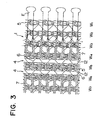
- Fig. 3 shows a warp-knit tape 1 according to a second embodiment.
- a chain-stitch yarn 5 of 1-0/0-1 a plurality of tricot-stitch yarns 6 of 1-2/1-0 and a plurality of weft-inlaid yarns 7 of 0-0/4-4 are interlooped and/or interlaced, thus restricting the entire warp-knit tape 1 in longitudinal stretchability.
- a narrow strip of retroreflective film 13 or any other reflective member 12 is located and is held by the tricot-stitch yarn 6 and a plurality of weft-inlaid yarns 7 on its front and rear sides, respectively.
- the tricot-stitch yarns 6 exposed over the front surfaces of the reflecting members 12 such as the retroreflective films 13 are each a transparent thermoplastic synthetic fiber yarn.
- the individual reflecting portion 4 is exposed to the front surface of the warp-knit tape 1 continuously along its entire length.
- Fig. 4 shows a warp-knit tape 1 according to a third embodiment.
- a plurality of two-needle-stitch yarns 8 of 0-2/2-0 and a plurality of weft-inlaid yarns 7 of 0-0/4-4 are interlooped and interlaced, respectively, thus restricting the entire warp-knit tape 1 in longitudinal stretchability of the warp-knit foundation.
- a narrow strip of retroreflective film 13 or any other reflective member 12 is located and is held by the two-needle-stitch yarn 8 and the plurality of weft-inlaid yarns 7 on its front and rear sides, respectively.
- the two-needle-stitch yarn 8 exposed over the front surface of the reflecting member 12 such as the retroreflective film 13 is a transparent thermoplastic synthetic fiber yarn.
- the reflecting portion 4 is exposed to the front surface of the warp-knit tape 1 continuously along its entire length. Having this two-needle-stitch yarn 8, the reflective member 12 such as the retroreflective film 13 can be held uniformly along its entire length.
- Fig. 5 shows a warp-knit tape 1 according to a fourth embodiment.
- a plurality of weft-inlaid yarns 7 of 3-3/0-0 are interlaced with a chain-stitch yarn 5 of 1-0/0-1, thus restricting the entire warp-knit tape 1 in longitudinal stretchability of the warp-knit foundation.
- a narrow strip of retroreflective film 13 or any other reflective member 12 is located.
- Such two reflective members 12 are held by a weft-inlaid yarn 9 of 3-3/0-0 and the plurality of weft-inlaid yarns 7 on their front and rear sides, respectively. And the fastener elements E are sewn onto one longitudinal edge of the tape 1.
- the weft-inlaid yarn 9 holding the front surface of the reflecting member 12 such as the retroreflective film 13 are each a transparent thermoplastic synthetic fiber yarn.
- the individual reflecting portion 4 is exposed to the front surface of the warp-knit tape 1 continuously along its entire length.
- Fig. 6 shows a warp-knit tape 1 according to a fifth embodiment.
- a plurality of tricot-stitch yarns 6 of 1-2/1-0 and a plurality of weft-inlaid yarns 7 of 0-0/4-4 are interlooped and interlaced, respectively, and in each of the first to fifth wales W 1 - W 5 , a chain-stitch yarn 5 is interlooped and interlaced with the tricot-stitch yarns 6 and the weft-inlaid yarns 7, respectively, thus restricting the warp-knit tape 1 in longitudinal stretchability of the warp-knit foundation.
- a narrow strip of retroreflective film 13 or any other reflective member 12 is located and the retroreflective film 13 is held by the tricot-stitch yarn 6 and the plurality of weft-inlaid yarns 7 on its front and rear sides, respectively.
- an additional weft-inlaid yarn 10 of 0-0/2-2 is located over the retroreflective film 13 so as to cross the tricot-stitch yarn 6.
- Both these tricot-stitch and weft-inlaid yarns 6, 10 exposed on the front surface of the reflecting member 12 such as the retroreflective film 13 are each a transparent thermoplastic synthetic fiber yarn.
- the chain-stitch yarns 5 of the first wale W 1 and the fourth and fifth adjacent wales W 4 , W 5 , which are located on opposite sides of the reflective member 12, may be each a large-size knitting yarn to increase especially the fourth and fifth wales W 4 , W 5 in volume than the remaining wales, thereby realizing protection of the reflective member 12.
- Fig. 7 shows a warp-knit tape 1 according to a sixth embodiment.
- a chain-stitch yarn 5 of 1-0/0-1 is knitted, and in each of the second to sixth wales W 2 - W 6 , a plurality of tricot-stitch yarns 6 of 1-2/1-0 and a plurality of weft-inlaid yarns 7 of 0-0/3-3 are interlooped and interlaced, respectively, with the chain-stitch yarn 5.
- the chain-stitch yarn 5 of the first wale W 1 is larger in size than the remaining chain-stitch yarns 5.
- one of various kinds of thick core cord 19 which is composed of a plurality of synthetic fiber threads or filaments, is located and is held by a pair of symmetrically arranged weft-inlaid yarns 30 of 0-0/1-1 on its front and rear sides.
- a narrow strip of retroreflective film 13 or any other reflective member 12 is located and is held as being sandwiched by the tricot-stitch yarn 6 and the weft-inlaid yarns 7, respectively.
- additional weft-inlaid yarns 10 of 0-0/1-1 are located over the reflective members 12 such as retroreflective film 13 so as to cross the tricot-stitch yarns 6.
- Both these tricot-stitch and weft-inlaid yarns 6, 10 exposed on the front surface of the reflecting member 12 such as the retroreflective film 13 are each a transparent thermoplastic synthetic fiber yarn.
- the reflecting portion 4 is exposed to the front surface of the warp-knit tape 1 continuously along its entire length.
- a row of fastener elements E may be molded of thermoplastic resin, such as polyamide, polypropylene or polybutyleneterephthalate, by injection molding means, or a row of metal fastener elements E may be mounted by pressing.
- Fig. 8 shows a modified warp-knit tape 1 of Fig. 7.
- This warp-knit tape 1 is identical in knit structure with that of the embodiment of Fig. 7.
- a chain-stitch yarn 5 of 1-0/0-1 is knitted, and in each of the second to sixth wales W 2 - W 6 , a plurality of tricot-stitch yarns 6 of 1-2/1-0 and a plurality of weft-inlaid yarns 7 of 0-0/3-3 are interlooped and interlaced, respectively, with the chain-stitch yarn 5.
- the chain-stitch yarn 5 of the first wale W 1 is larger in size than the remaining chain-stitch yarns 5.
- one of various kinds of thick core cord 19, which is composed of a plurality of synthetic fiber threads or filaments, is located and is held by a pair of symmetrically arranged weft-inlaid yarns 30 of 0-0/1-1 on its front and rear sides.
- each of between the fourth and fifth adjacent wales W 4 , W 5 and the fifth and sixth adjacent wales W 5 , W 6 a pair of narrow strips of retroreflective film 13 or a pair of any other reflective members 12 are located and are held as being sandwiched by the tricot-stitch yarn 6 and the weft-inlaid yarns 7, respectively.
- additional weft-inlaid yarns 10 of 0-0/1-1 are located over the pair of reflective members 12 such as the pair of narrow strips of retroreflective film 13 so as to cross the tricot-stitch yarns 6.
- the number of reflective members 12 to be knitted in the warp-knit tape 1 as a single reflecting portion 4 should by no means be limited to two and may be more than two and less than many.
- a narrow strip of retroreflective film 13 is wound around the circumferential surface of a core cord 18 of a thermoplastic synthetic fiber yarn and such wound core cords or strings, or silver or gold threads may be disposed in parallel.
- Each reflective member 12 may be composed of a cord formed by knitting or by braiding the wound core cord or string, or silver or gold threads.
- Fig. 9 shows a warp-knit tape 1 according to a seventh embodiment.
- a chain-stitch yarn 5 of 1-0/0-1 is knitted, and only the chain-stitch yarn 5 of the first wale W 1 is larger in size than the remaining chain-stitch yarns 5.
- a plurality of tricot-stitch yarns 6 of 1-2/1-0 and a plurality of weft-inlaid yarns 7 of 0-0/3-3 are interlooped and interlaced, respectively, with the chain-stitch yarn 5.
- the tricot-stitch yarns 6 extending between the fifth and sixth adjacent wales W 5 , W 6 and between the sixth and seventh adjacent wales W 6 , W 7 are each composed of a reflective member 12 in the form of a knitting yarn in which a core cord 18 is in the form of a thermoplastic synthetic fiber yarn, and a narrow strip of retroreflecting film 13 is wound around the circumferential surface of the core cord 18, as shown in Fig. 16, or a knitting yarn around which a narrow strip of light-reserve reflective film 20 is wound, as shown in Fig. 17, or each in the form of a thermoplastic synthetic fiber yarn dyed with a fluorescent dye or fluorescent white dye or bleached with a fluorescent bleach, or each in the form of a silver or gold thread.
- the kind of the knitting yarns to be used as the reflective members 12 each constituting a reflecting portion 4 should by no means be limited to tricot-stitch yarns and may be chain-stitch yarns, two-needle-stitch yarns, single-cord-stitch yarns or even mere weft-inlaid yarns, as long as they are located and knitted in and between a necessary number of wales.
- the resulting reflecting portion 4 serves to produce a continuous reflecting feature along the entire length of the warp-knit tape 1.
- Fig. 10 shows a warp-knit tape 1 according to an eighth embodiment.
- a chain-stitch yarn 5 of 1-0/0-1 is knitted, and only the chain-stitch yarn 5 of the first wale W 1 is larger in size than the remaining chain-stitch yarns 5.
- a plurality of tricot-stitch yarns 6 of 1-2/1-0 and a plurality of weft-inlaid yarns 7 of 0-0/3-3 are interlooped and interlaced, respectively, of the chain-stitch yarn 5.
- a reflective member 12 composed of a narrow strip of retroreflective film 13 or any other reflective member 12 is located and is held by a tricot-stitch yarn 6 and a plurality of weft-inlaid yarns 7, respectively on its front and rear sides.
- the tricot-stitch yarns 6 of 1-2/1-0 extending between the fifth and sixth adjacent wales W 5 , W 6 and between the sixth and seventh adjacent wales W 6 , W 7 are each composed of the reflective member 12 in the form of a knitting yarn in which a core cord 18 is in the form of a thermoplastic synthetic fiber yarn, and a narrow strip of retroreflective film 13 is wound around the core cord 18, or a knitting yarn around which a narrow strip of light-reserve reflective film 20 is wound, or each in the form of a thermoplastic synthetic fiber yarn dyed with a fluorescent dye or fluorescent white dye or bleached with a fluorescent bleach, or each in the form of a silver or gold thread so that the continuous reflecting portions 4 can be formed.
- each reflecting portion 4 is constituted by combining the two different kinds of reflective members 12 in an overlapping relationship, it can produce a reflecting feature with maximum definition.
- Fig. 11 shows a warp-knit tape 1 according to a ninth embodiment.
- a chain-stitch yarn 5 of 1-0/0-1 is knitted, and only the chain-stitch yarn 5 of the first wale W 1 is larger in size than the remaining chain-stitch yarns 5.
- a plurality of tricot-stitch yarns 6 of 1-2/1-0 and a plurality of weft-inlaid yarns 7 of 0-0/3-3 are interlooped and interlaced, respectively, with the chain-stitch yarn 5 of 1-0/0-1.
- a reflective member 12 which is composed of a core cord 18 of a thermoplastic synthetic fiber yarn and a narrow strip of retroreflective film 13 wound around the core cord 18, or composed of a knitting yarn and a narrow strip of light-reserve reflective film 20 wound around the knitting yarn, or a knitting yarn of a thermoplastic synthetic fiber yarn dyed with a fluorescent dye or fluorescent white dye or bleached with a fluorescent bleach, or a silver or gold yarn is used so that a continuous reflecting portion 4 is formed.
- a row of fastener elements E may be molded of thermoplastic resin or a row of metal fastener elements E may be mounted, thus completing a continuous length of slide fastener stringer.
- Fig. 12 shows a warp-knit tape 1 according to a tenth embodiment.
- a chain-stitch yarn 5 of 1-0/0-1 a plurality of tricot-stitch yarns 6 of 1-2/1-0 and a plurality of weft-inlaid yarns 7 of 0-0/4-4 are interlooped and/or interlaced to form the warp-knit foundation.
- yarns 11 of 0-0/0-0/0-0/1-1/1-1/1-1 are laid in and along the fifth and sixth adjacent wales W 5 , W 6 , respectively, using reflective members 12 each composed of a core cord 18, which is in the form of a thermoplastic synthetic fiber yarn, and a narrow strip of retroreflective film 13 or a narrow strip of light-reserve reflective film 20 wound around the core cord 18, as shown in Fig.
- each warp-inlaid yarn 11 is interlaced with the chain-stitch yarn 5 of a respective one of the fifth and sixth wales W 5 , W 6 at every three courses.
- the chain-stitch yarns 5 and the tricot-stitch yarns 6 in the fifth and sixth adjacent wales W 5 , W 6 are transparent thermoplastic synthetic fiber yarns and, as a result, a pair of parallel continuous reflecting portions 4 are formed in the web portion 3 along the entire length of the warp-knit tape 1.
- Fig. 13 shows a warp-knit tape 1 according to an eleventh embodiment.
- a chain-stitch yarn 5 of 1-0/0-1 a plurality of tricot-stitch yarns 6 of 1-2/1-0 and a plurality of weft-inlaid yarns 7 of 0-0/4-4 are interlooped and/or interlaced to form the warp-knit foundation.
- a pair of analogous warp-inlaid yarns 11 of 0-0/0-0/0-0/1-1/1-1/1-1 and 1-1/1-1/1-1/0-0/0-0/0-0, respectively, are laid in and along the fifth and sixth adjacent wales W 5 , W 6 , using reflective members 12 each composed of a core cord 18 of a thermoplastic synthetic fiber yarn and a narrow strip of retroreflective film 13 or a narrow strip of light-reserve reflective film 20 wound around the core cord 18, or each being a thermoplastic synthetic fiber yarn dyed with a fluorescent dye or fluorescent white dye or bleached with a fluorescent bleach, or a silver or gold thread.
- each of the fifth and sixth wales W 5 , W 6 of the pair of warp-inlaid yarns 11 are knitted symmetrically in a pattern of 0-0/0-0/0-0/1-1/1-1/1-1 and a pattern of 1-1/1-1/1-1/0-0/0-0/0-0 with the chain-stitch yarns 5 of 1-2/1-0, crossing each other at every three courses.
- the chain-stitch yarns 5 and the tricot-stitch yarns 6 in the fifth and sixth adjacent wales W 5 , W 6 are transparent thermoplastic synthetic fiber yarns.
- a pair of continuous uniform rather wide reflecting portions 4 are formed in the web portion 3 along the entire length of the warp-knit tape 1.
- Fig. 14 shows a warp-knit tape 1 according to a twelfth embodiment.
- a plurality of tricot-stitch yarns 6 of 1-2/1-0 and a plurality of weft-inlaid yarns 7 of 0-0/4-4 are interlooped and interlaced, respectively, and in each of the first to fourth wales W 1 - W 4 (right marginal portion 2) and fifteenth to eighteenth wales W 15 - W 18 (left marginal portion 2), a chain-stitch yarn 5 of 1-0/0-1 is interlooped and interlaced with the tricot-stitch yarn 6 and the weft-inlaid yarn 7, respectively to form a warp-knit foundation.
- a narrow strip of retroreflective film 13 as a reflective member 12 or any other reflective member 12 is located and is knitted to be held as being sandwiched by the tricot-stitch yarn 6 and the weft-inlaid yarn 7 on its front and rear sides, respectively.
- the tricot-stitch yarns 6 exposed over the front surfaces of the reflective members 12 such as the retroreflective films 13 are each a transparent thermoplastic synthetic fiber yarn.
- a row of fastener elements are attached to one of the two marginal portions 2 such as by sewing; accordingly, either marginal portion 2, i.e., either W 1 - W 4 or W 15 - W 18 may serve to support the fastener element row and is hence called the element-attaching marginal portion 2. Therefore, the warp-knit tape 1 of the present invention can be used to manufacture either one of two opposite fastener stringers.
- the warp-knit tape 1 of this invention should by no means be limited to the illustrated examples and its warp-knit structure may be composed of various knitting yarns in any optional combination; stitches of the individual knitting yarn may be either open stitches or closed stitches. Further, regarding the width of the warp-knit tape 1 and the location of the reflective member 12, various changes or modifications may be made to meet the purpose of use.
- the number of the reflective members 12 should by no means be limited to two and may be more than two and less than many.
- the reflective members 12 to be knitted may be each composed not only of a core cord 18 of a thermoplastic synthetic fiber yarn and a narrow strip of retroreflective film 13 wound around the circumferential surface of the core cord 18, as shown in Fig. 16, or of a knitting yarn and a narrow strip of light-reserve reflective film 20 wound around the knitting yarn, as shown in Fig. 17, or of a thermoplastic synthetic fiber yarn dyed with a fluorescent dye or fluorescent white dye or bleached with a fluorescent bleach, or of a silver or gold thread, disposed in parallel, but also of a cord formed by knitting or by braiding such wound cord, or silver or gold thread.
Landscapes
- Engineering & Computer Science (AREA)
- Textile Engineering (AREA)
- Knitting Of Fabric (AREA)
- Slide Fasteners (AREA)
- Decoration Of Textiles (AREA)
- Optical Elements Other Than Lenses (AREA)
Claims (19)
- Ruban tricoté chaíne réfléchissant (1) pour fermeture à glissière comportant une pluralité de sortes de structures tricotées chaíne, comprenant une partie toile longitudinale (3); et une partie marginale (2) de fixation d'éléments s'étendant de manière contiguë à et le long d'un bord longitudinal de ladite partie toile (3), ladite partie marginale (2) de fixation d'éléments comportant une structure tricotée qui n'est pas extensible dans le sens longitudinal,
caractérisé en ce que ladite partie toile (3) comprend une portion réfléchissante (4) constituée par au moins un élément réfléchissant (12) fait d'un matériau réfléchissant et en ce que ledit élément réfléchissant est tricoté dans ladite partie toile. - Ruban tricoté chaíne réfléchissant selon la revendication 1, caractérisé en ce que ladite portion réfléchissante (4) est réalisée en tricotant l'élément réfléchissant (12) de façon adjacente à un côté intérieur dudit bord longitudinal de ladite partie marginale (2) de ladite partie toile (3) de manière à ce qu'il s'étende sensiblement parallèlement à ladite partie (2) de fixation d'éléments.
- Ruban tricoté chaíne réfléchissant selon la revendication 1 ou 2, caractérisé en ce que ladite portion réfléchissante (4) est réalisée en tricotant ledit élément réfléchissant (12) en tant que trame en position centrale dans ladite partie toile (3) de manière à ce qu'elle s'étende dans le sens longitudinal de celle-ci.
- Ruban tricoté chaíne réfléchissant selon l'une quelconque des revendications qui précèdent, caractérisé en ce que des côtes de ladite partie toile (3) qui sont situées sur des côtés opposés de ladite portion réfléchissante (4) sont plus volumineuses que les autres côtes.
- Ruban tricoté chaíne réfléchissant selon l'une quelconque des revendications qui précèdent, caractérisé en ce que ledit élément réfléchissant (12) constitué par une bande de film réfléchissant est incorporé par tricotage de manière à être situé entre des côtes adjacentes et à être maintenu par et pris en sandwich entre d'autres fils de tricotage.
- Ruban tricoté chaíne réfléchissant selon l'une quelconque des revendications qui précèdent, caractérisé en ce que ledit élément réfléchissant (12) constitué par une bande de film réfléchissant est incorporé par tricotage de manière à être situé entre des côtes adjacentes et à être maintenu par et pris en sandwich entre d'autres fils de tricotage et en ce que lesdits fils de tricotage ont des armures de tricotage différentes, si bien qu'une surface endroit de l'élément réfléchissant est maintenue et prise en sandwich par une pluralité desdits fils de tricotage.
- Ruban tricoté chaíne réfléchissant selon l'une quelconque des revendications qui précèdent, caractérisé en ce que ledit élément réfléchissant (12) est incorporé par tricotage afin d'être situé entre des côtes adjacentes et d'être maintenu par et pris en sandwich entre d'autres fils de tricotage et en ce que ceux des fils de tricotage qui sont visibles sur une surface endroit de l'élément réfléchissant (12) sont des fils de fibres synthétiques thermoplastiques transparentes.
- Ruban tricoté chaíne réfléchissant selon l'une quelconque des revendications qui précèdent, caractérisé en ce que ledit élément réfléchissant (12) constitué par une bande de film réfléchissant est incorporé par tissage de manière à être situé entre des côtes adjacentes et à être maintenu par d'autres fils de tricotage et à être pris en sandwich entre ceux-ci et en ce que lesdits fils de tricotage sont tricotés selon une armure de tricotage de manière à s'étendre parallèlement aux rangs de ladite partie toile (3) de telle sorte que la surface endroit dudit élément réfléchissant (12) est maintenue par lesdits fils de tricotage s'étendant parallèlement auxdits rangs.
- Ruban tricoté chaíne réfléchissant selon l'une quelconque des revendications qui précèdent, caractérisé en ce que ledit élément réfléchissant (12) se présente sous la forme d'une bande étroite de film rétroréfléchissant (13) incorporée par tricotage afin d'être située entre des côtes adjacentes et d'être maintenue par et prise en sandwich entre d'autres fils de tricotage.
- Ruban tricoté chaíne réfléchissant selon l'une quelconque des revendications qui précèdent, caractérisé en ce que ledit élément réfléchissant (12) qui est constitué par un cordonnet (18) formant âme d'un fil de fibres synthétiques thermoplastiques et par une bande étroite de film rétroréfléchissant (13) enroulée autour dudit cordonnet formant âme (8) est incorporé par tricotage de manière à être situé entre des côtes adjacentes et à être maintenu par et pris en sandwich entre d'autres fils de tricotage.
- Ruban tricoté chaíne réfléchissant selon l'une quelconque des revendications qui précèdent, caractérisé en ce que ledit élément réfléchissant (12) qui se présente sous la forme d'un film (20) réfléchissant à réserve de lumière est incorporé par tricotage de manière à être situé entre des côtes adjacentes et à être maintenu par et pris en sandwich entre d'autres fils de tricotage.
- Ruban tricoté chaíne réfléchissant selon l'une quelconque des revendications qui précèdent, caractérisé en ce que ledit élément réfléchissant (12) qui se présente sous la forme d'une bande de film (20) réfléchissant à réserve de lumière est incorporé par tissage de manière à être situé entre des côtes adjacentes et à être maintenu par et pris en sandwich entre d'autres fils de tricotage.
- Ruban tricoté chaíne réfléchissant selon l'une quelconque des revendications qui précèdent, caractérisé en ce qu'une pluralité de dits éléments réfléchissants (12) sont chacun incorporés par tricotage de manière à être situés entre des côtes adjacentes et à être maintenus par et pris en sandwich entre d'autres fils de tricotage et en ce que lesdits autres fils de tricotage sont deux ou plusieurs fils de tricotage de sortes différentes.
- Ruban tricoté chaíne réfléchissant selon l'une quelconque des revendications qui précèdent, caractérisé en ce que ledit élément réfléchissant (12) est un fil de tricotage composé d'un cordonnet (18) formant âme constitué d'un fil de fibres synthétiques thermoplastiques et d'une bande étroite de film rétroréfléchissant (13) enroulée autour dudit cordonnet (18) formant âme et en ce que chacun desdits fils de tricotage forme une côte.
- Ruban tricoté chaíne réfléchissant selon l'une quelconque des revendications qui précèdent, caractérisé en ce que ledit élément réfléchissant (12) est un fil de tricotage qui se présente sous la forme d'un fil de fibres synthétiques thermoplastiques teintes avec un colorant fluorescent et en ce que chacun desdits fils de tricotage forme une côte.
- Ruban tricoté chaíne réfléchissant selon l'une quelconque des revendications qui précèdent, caractérisé en ce que ledit élément réfléchissant (12) est un fil de tricotage qui se présente sous la forme d'un fil d'argent ou d'or, et en ce que chacun desdits fils de tricotage forme une côte.
- Ruban tricoté chaíne réfléchissant selon l'une quelconque des revendications qui précèdent, caractérisé en ce que ledit élément réfléchissant (12) est un fil de tricotage constitué par un fil de fibres synthétiques thermoplastiques, et en ce que lesdits fils de tricotage forment deux ou plusieurs côtes.
- Ruban tricoté chaíne réfléchissant selon l'une quelconque des revendications qui précèdent, caractérisé en ce que lesdits éléments réfléchissants (12) sont une pluralité de fils de tricotage dont chacun se présente sous la forme d'un fil de fibres synthétiques thermoplastiques, lesquels fils de tricotage sont incorporés par tricotage en tant que fils de chaíne incorporés qui sont chacun entrelacés avec une des sortes de dits fils de tricotage d'une côte tous les deux ou trois rangs, et en ce que chacun desdits éléments réfléchissants (12) est situé au-dessus d'autres fils de tricotage entre des côtes adjacentes.
- Ruban tricoté chaíne réfléchissant selon l'une quelconque des revendications qui précèdent, caractérisé en ce que lesdits éléments réfléchissants (12) sont deux ou plusieurs fils de tricotage dont chacun est un fil de fibres synthétiques thermoplastiques, incorporé par tricotage en tant que fil de chaíne incorporé, dont chacun est entrelacé avec une des sortes de dits fils de tricotage d'une côte tous les deux ou trois rangs et en ce que ces deux ou plusieurs éléments réfléchissants (12) sont répartis uniformément sur les côtés opposés d'une côte, parallèlement l'un à l'autre, ou les uns aux autres.
Applications Claiming Priority (6)
| Application Number | Priority Date | Filing Date | Title |
|---|---|---|---|
| JP11485397A JP3526389B2 (ja) | 1997-05-02 | 1997-05-02 | 反射性スライドファスナー用経編テープ |
| JP11485497A JP3526390B2 (ja) | 1997-05-02 | 1997-05-02 | 反射性スライドファスナー用経編テープ |
| JP114853/97 | 1997-05-02 | ||
| JP11485497 | 1997-05-02 | ||
| JP11485397 | 1997-05-02 | ||
| JP114854/97 | 1997-05-02 |
Publications (2)
| Publication Number | Publication Date |
|---|---|
| EP0875165A1 EP0875165A1 (fr) | 1998-11-04 |
| EP0875165B1 true EP0875165B1 (fr) | 2003-02-26 |
Family
ID=26453511
Family Applications (1)
| Application Number | Title | Priority Date | Filing Date |
|---|---|---|---|
| EP19980108004 Expired - Lifetime EP0875165B1 (fr) | 1997-05-02 | 1998-04-30 | Rudan à tricot chaíne réfléchissant pour fermeture à glissière |
Country Status (10)
| Country | Link |
|---|---|
| US (1) | US6180545B1 (fr) |
| EP (1) | EP0875165B1 (fr) |
| KR (1) | KR100275418B1 (fr) |
| CN (1) | CN1081451C (fr) |
| BR (1) | BR9801983A (fr) |
| DE (1) | DE69811554T2 (fr) |
| ES (1) | ES2189033T3 (fr) |
| ID (1) | ID20240A (fr) |
| SG (1) | SG71784A1 (fr) |
| TW (1) | TW497962B (fr) |
Families Citing this family (22)
| Publication number | Priority date | Publication date | Assignee | Title |
|---|---|---|---|---|
| JP3707982B2 (ja) * | 2000-03-08 | 2005-10-19 | Ykk株式会社 | 経編組織からなるスライドファスナー用テープ |
| JP3808351B2 (ja) * | 2001-11-21 | 2006-08-09 | Ykk株式会社 | ファスナー |
| JP4071095B2 (ja) * | 2002-12-04 | 2008-04-02 | Ykk株式会社 | 反射性スライドファスナー |
| US6886949B2 (en) * | 2003-02-19 | 2005-05-03 | Ykk Corporation Of America | Light reflective films |
| JP4387124B2 (ja) * | 2003-05-30 | 2009-12-16 | Ykk株式会社 | スライドファスナー用テープと同テープを使ったスライドファスナー用ストリンガー |
| US7295423B1 (en) * | 2003-07-09 | 2007-11-13 | Maxwell Technologies, Inc. | Dry particle based adhesive electrode and methods of making same |
| US20050048263A1 (en) * | 2003-08-26 | 2005-03-03 | Schlegel Corporation | Reflective surface for a vehicle weatherseal |
| US7181933B2 (en) * | 2004-08-27 | 2007-02-27 | Milliken & Company | Tape substrate and tape made therefrom |
| JP4808596B2 (ja) * | 2006-11-21 | 2011-11-02 | デジタルファッション株式会社 | 編構造モデル生成プログラム、編構造モデル生成装置、及び編構造モデル生成方法 |
| RU2333302C1 (ru) * | 2007-01-22 | 2008-09-10 | Государственное образовательное учреждение высшего профессионального образования "Московский государственный текстильный университет им. А.Н. Косыгина" | Однослойный основовязаный комбинированный трикотаж |
| DE202007006958U1 (de) * | 2007-05-11 | 2007-07-26 | X-Technology Swiss Gmbh | Kleidungsstück |
| TWM508937U (zh) * | 2015-02-26 | 2015-09-21 | Charm Young Industry Co Ltd | 針織經編隱形拉鍊帶 |
| CN106012169A (zh) * | 2016-07-27 | 2016-10-12 | 上海曙雀贸易有限公司 | 一种反光线的制备方法 |
| CN106544782B (zh) * | 2016-09-18 | 2018-03-27 | 福建省百凯弹性织造有限公司 | 一种反光织带及其制备方法 |
| JP3208550U (ja) * | 2016-11-07 | 2017-01-26 | Ykk株式会社 | スライドファスナー用ファスナーテープ及びスライドファスナー |
| KR101929406B1 (ko) * | 2017-05-25 | 2018-12-14 | 윤세원 | 재귀반사시트 |
| KR101962450B1 (ko) * | 2018-11-09 | 2019-07-17 | 주식회사 에코앤휴먼 | 유색식별부와 재귀반사식별부를 구비하는 신축형 반사밴드 안전 표시구 |
| TWM578237U (zh) * | 2018-11-30 | 2019-05-21 | 萬核應用材料有限公司 | 複合布料 |
| US11564448B2 (en) | 2019-05-10 | 2023-01-31 | Converse Inc. | Reflective textile |
| CN210870147U (zh) * | 2019-08-08 | 2020-06-30 | Ykk株式会社 | 拉链链带及具备其的拉链 |
| JP7686658B2 (ja) * | 2020-09-30 | 2025-06-02 | 日鉄ケミカル&マテリアル株式会社 | メッシュ状繊維強化複合材、メッシュ状編み構造体、メッシュ状繊維強化複合材成形用材料及びメッシュ状繊維強化複合材成形体 |
| CN114431580A (zh) * | 2020-10-30 | 2022-05-06 | 台湾华可贵股份有限公司 | 拉链带与拉链带的制作方法 |
Family Cites Families (7)
| Publication number | Priority date | Publication date | Assignee | Title |
|---|---|---|---|---|
| JPS5421781B2 (fr) * | 1972-12-29 | 1979-08-02 | ||
| FR2335124A7 (fr) * | 1975-12-09 | 1977-07-08 | Prestil | Fermeture a glissiere |
| JPS5951807B2 (ja) * | 1981-02-26 | 1984-12-15 | ワイケイケイ株式会社 | スライドフアスナ−用テ−プ |
| SE436164B (sv) * | 1982-11-10 | 1984-11-19 | Svensson Ludvig Bv | Vexthusgardin |
| FR2625017A1 (fr) * | 1987-12-22 | 1989-06-23 | Caoutchouc Manuf Extra Souple | Bande en tissu retroreflechissante et son procede d'obtention |
| US4871597A (en) * | 1988-02-08 | 1989-10-03 | Hobson Michael A | Light-weight multi-layer insulating enclosure |
| JPH09228205A (ja) * | 1996-02-29 | 1997-09-02 | Ykk Corp | 反射性経編テープ |
-
1998
- 1998-04-16 SG SG1998000843A patent/SG71784A1/en unknown
- 1998-04-23 TW TW87106272A patent/TW497962B/zh not_active IP Right Cessation
- 1998-04-29 CN CN98107472A patent/CN1081451C/zh not_active Expired - Lifetime
- 1998-04-30 DE DE69811554T patent/DE69811554T2/de not_active Expired - Lifetime
- 1998-04-30 ES ES98108004T patent/ES2189033T3/es not_active Expired - Lifetime
- 1998-04-30 EP EP19980108004 patent/EP0875165B1/fr not_active Expired - Lifetime
- 1998-04-30 BR BR9801983A patent/BR9801983A/pt not_active IP Right Cessation
- 1998-05-01 US US09/071,742 patent/US6180545B1/en not_active Expired - Fee Related
- 1998-05-01 ID ID980654A patent/ID20240A/id unknown
- 1998-05-02 KR KR1019980015848A patent/KR100275418B1/ko not_active Expired - Fee Related
Also Published As
| Publication number | Publication date |
|---|---|
| HK1016664A1 (en) | 1999-11-05 |
| US6180545B1 (en) | 2001-01-30 |
| DE69811554T2 (de) | 2003-12-11 |
| KR100275418B1 (ko) | 2000-12-15 |
| TW497962B (en) | 2002-08-11 |
| BR9801983A (pt) | 1999-11-09 |
| DE69811554D1 (de) | 2003-04-03 |
| SG71784A1 (en) | 2000-04-18 |
| ID20240A (id) | 1998-11-05 |
| CN1081451C (zh) | 2002-03-27 |
| EP0875165A1 (fr) | 1998-11-04 |
| KR19980086725A (ko) | 1998-12-05 |
| CN1202543A (zh) | 1998-12-23 |
| ES2189033T3 (es) | 2003-07-01 |
Similar Documents
| Publication | Publication Date | Title |
|---|---|---|
| US6180545B1 (en) | Reflecting warp-knit tape for slide fastener | |
| US20040111842A1 (en) | Reflective slide fastener and reflective tape | |
| JP3580350B2 (ja) | 反射性スライドファスナー | |
| US5728448A (en) | Reflective warp-knit tape | |
| US5983465A (en) | Fastener tape and stringer for a slide fastener chain | |
| US5956818A (en) | Retroreflective filament slide fastner | |
| JPH0479242B2 (fr) | ||
| EP1112700B1 (fr) | Fermeture à glissière | |
| EP0749708B1 (fr) | Ruban tricoté en chaíne pour fermeture à glissière | |
| KR100288953B1 (ko) | 슬라이드파스너용체인 | |
| JP3526389B2 (ja) | 反射性スライドファスナー用経編テープ | |
| JP3526390B2 (ja) | 反射性スライドファスナー用経編テープ | |
| ITTO980664A1 (it) | Catena di cerniera lampo. | |
| JPH0744883B2 (ja) | スライドファスナー用熱接着ストリンガーテープ | |
| CN213756919U (zh) | 拉链链带及具备其的拉链 | |
| JPH0542731Y2 (fr) | ||
| CN1227736A (zh) | 自扣接带 | |
| HK1016664B (en) | Reflecting warp-knit tape for slide fastener | |
| CN1163955A (zh) | 反光经向针织带 | |
| JP2003227049A (ja) | 反射性テープの製造方法とその反射性テープ | |
| HK1001408A (en) | Reflective warp-knit tape | |
| HK1062522A (en) | Reflective slide fastener and reflective tape | |
| HK1018387A (en) | Slide fastener chain | |
| HK1010647B (en) | Warp-knit tape for slide fastener |
Legal Events
| Date | Code | Title | Description |
|---|---|---|---|
| PUAI | Public reference made under article 153(3) epc to a published international application that has entered the european phase |
Free format text: ORIGINAL CODE: 0009012 |
|
| AK | Designated contracting states |
Kind code of ref document: A1 Designated state(s): DE ES FR GB IT |
|
| AX | Request for extension of the european patent |
Free format text: AL;LT;LV;MK;RO;SI |
|
| 17P | Request for examination filed |
Effective date: 19990208 |
|
| AKX | Designation fees paid |
Free format text: DE ES FR GB IT |
|
| 17Q | First examination report despatched |
Effective date: 20010925 |
|
| GRAG | Despatch of communication of intention to grant |
Free format text: ORIGINAL CODE: EPIDOS AGRA |
|
| GRAG | Despatch of communication of intention to grant |
Free format text: ORIGINAL CODE: EPIDOS AGRA |
|
| GRAG | Despatch of communication of intention to grant |
Free format text: ORIGINAL CODE: EPIDOS AGRA |
|
| GRAH | Despatch of communication of intention to grant a patent |
Free format text: ORIGINAL CODE: EPIDOS IGRA |
|
| GRAH | Despatch of communication of intention to grant a patent |
Free format text: ORIGINAL CODE: EPIDOS IGRA |
|
| GRAA | (expected) grant |
Free format text: ORIGINAL CODE: 0009210 |
|
| AK | Designated contracting states |
Designated state(s): DE ES FR GB IT |
|
| REG | Reference to a national code |
Ref country code: GB Ref legal event code: FG4D |
|
| REF | Corresponds to: |
Ref document number: 69811554 Country of ref document: DE Date of ref document: 20030403 Kind code of ref document: P |
|
| REG | Reference to a national code |
Ref country code: ES Ref legal event code: FG2A Ref document number: 2189033 Country of ref document: ES Kind code of ref document: T3 |
|
| ET | Fr: translation filed | ||
| PLBE | No opposition filed within time limit |
Free format text: ORIGINAL CODE: 0009261 |
|
| STAA | Information on the status of an ep patent application or granted ep patent |
Free format text: STATUS: NO OPPOSITION FILED WITHIN TIME LIMIT |
|
| 26N | No opposition filed |
Effective date: 20031127 |
|
| PGFP | Annual fee paid to national office [announced via postgrant information from national office to epo] |
Ref country code: GB Payment date: 20100325 Year of fee payment: 13 |
|
| PGFP | Annual fee paid to national office [announced via postgrant information from national office to epo] |
Ref country code: FR Payment date: 20100521 Year of fee payment: 13 Ref country code: ES Payment date: 20100423 Year of fee payment: 13 |
|
| PGFP | Annual fee paid to national office [announced via postgrant information from national office to epo] |
Ref country code: DE Payment date: 20100430 Year of fee payment: 13 |
|
| REG | Reference to a national code |
Ref country code: DE Ref legal event code: R119 Ref document number: 69811554 Country of ref document: DE |
|
| REG | Reference to a national code |
Ref country code: DE Ref legal event code: R119 Ref document number: 69811554 Country of ref document: DE |
|
| GBPC | Gb: european patent ceased through non-payment of renewal fee |
Effective date: 20110430 |
|
| REG | Reference to a national code |
Ref country code: FR Ref legal event code: ST Effective date: 20111230 |
|
| PG25 | Lapsed in a contracting state [announced via postgrant information from national office to epo] |
Ref country code: FR Free format text: LAPSE BECAUSE OF NON-PAYMENT OF DUE FEES Effective date: 20110502 |
|
| PG25 | Lapsed in a contracting state [announced via postgrant information from national office to epo] |
Ref country code: GB Free format text: LAPSE BECAUSE OF NON-PAYMENT OF DUE FEES Effective date: 20110430 |
|
| REG | Reference to a national code |
Ref country code: ES Ref legal event code: FD2A Effective date: 20120524 |
|
| PG25 | Lapsed in a contracting state [announced via postgrant information from national office to epo] |
Ref country code: ES Free format text: LAPSE BECAUSE OF NON-PAYMENT OF DUE FEES Effective date: 20110501 |
|
| PG25 | Lapsed in a contracting state [announced via postgrant information from national office to epo] |
Ref country code: DE Free format text: LAPSE BECAUSE OF NON-PAYMENT OF DUE FEES Effective date: 20111031 |
|
| PGFP | Annual fee paid to national office [announced via postgrant information from national office to epo] |
Ref country code: IT Payment date: 20150413 Year of fee payment: 18 |
|
| PG25 | Lapsed in a contracting state [announced via postgrant information from national office to epo] |
Ref country code: IT Free format text: LAPSE BECAUSE OF NON-PAYMENT OF DUE FEES Effective date: 20160430 |