EP0875178A2 - Glissière pour tiroir parallèle - Google Patents
Glissière pour tiroir parallèle Download PDFInfo
- Publication number
- EP0875178A2 EP0875178A2 EP98104106A EP98104106A EP0875178A2 EP 0875178 A2 EP0875178 A2 EP 0875178A2 EP 98104106 A EP98104106 A EP 98104106A EP 98104106 A EP98104106 A EP 98104106A EP 0875178 A2 EP0875178 A2 EP 0875178A2
- Authority
- EP
- European Patent Office
- Prior art keywords
- extension
- parallel
- extension part
- insert
- pull
- Prior art date
- Legal status (The legal status is an assumption and is not a legal conclusion. Google has not performed a legal analysis and makes no representation as to the accuracy of the status listed.)
- Granted
Links
- 238000003780 insertion Methods 0.000 claims description 55
- 230000037431 insertion Effects 0.000 claims description 55
- 238000005096 rolling process Methods 0.000 claims description 40
- 230000008878 coupling Effects 0.000 claims description 20
- 238000010168 coupling process Methods 0.000 claims description 20
- 238000005859 coupling reaction Methods 0.000 claims description 20
- 238000006073 displacement reaction Methods 0.000 claims description 6
- 238000004146 energy storage Methods 0.000 claims description 6
- 230000004888 barrier function Effects 0.000 claims 1
- 239000000969 carrier Substances 0.000 claims 1
- 210000002105 tongue Anatomy 0.000 description 7
- 238000000034 method Methods 0.000 description 3
- 230000002996 emotional effect Effects 0.000 description 2
- 230000007613 environmental effect Effects 0.000 description 2
- 230000002349 favourable effect Effects 0.000 description 2
- 230000008569 process Effects 0.000 description 2
- 230000009286 beneficial effect Effects 0.000 description 1
- 230000000903 blocking effect Effects 0.000 description 1
- 238000010276 construction Methods 0.000 description 1
- 238000000605 extraction Methods 0.000 description 1
- 230000003993 interaction Effects 0.000 description 1
- 238000003825 pressing Methods 0.000 description 1
- 230000009467 reduction Effects 0.000 description 1
- 230000000630 rising effect Effects 0.000 description 1
- 230000001960 triggered effect Effects 0.000 description 1
Images


Classifications
-
- A—HUMAN NECESSITIES
- A47—FURNITURE; DOMESTIC ARTICLES OR APPLIANCES; COFFEE MILLS; SPICE MILLS; SUCTION CLEANERS IN GENERAL
- A47B—TABLES; DESKS; OFFICE FURNITURE; CABINETS; DRAWERS; GENERAL DETAILS OF FURNITURE
- A47B88/00—Drawers for tables, cabinets or like furniture; Guides for drawers
- A47B88/40—Sliding drawers; Slides or guides therefor
- A47B88/49—Sliding drawers; Slides or guides therefor with double extensible guides or parts
- A47B88/493—Sliding drawers; Slides or guides therefor with double extensible guides or parts with rollers, ball bearings, wheels, or the like
Definitions
- the insert By the interaction of the first and the second parallel guide element is achieved that the insert always so remains aligned that a smooth pulling out of the Inserts from the body and an equally smooth insertion of the insertion in the body exactly parallel to the by the orientation of the pull-out guides is possible.
- the extension part ensures that the rolling element when pulling the drawer out of the body further in the direction of extension can be moved forward than this without the extension part would be the case.
- the present invention is therefore based on the object a parallel extension of the type mentioned above to improve that the extension part in the insertion position is arranged to save space, so that the parallel extension equally suitable for inserts of any height is.
- the concept according to the invention enables the second rolling bar of the extension part in the insertion position in to be arranged essentially parallel to the pull-out direction, so that of the extension part in the insertion position space essentially occupied transversely to the direction of extension regardless of the distance around which the second scroll bar is the first scroll bar is extended, and thus also at low Inserts of sufficiently large extensions of the first Scroll bar can be reached.
- the space required for the extension part transverse to the direction of extension can be kept particularly low if the extension part along the extension direction relative to the base part is movable.
- the movement of the extension part from the insertion position into the Extension position relative to the base part next to an in essential linear displacement also a swivel or Includes tilting movement, in particular a swivel or Tilt movement through a small angle through which the extension part is locked in a locking position.
- extension part has a driving surface on which when pulling out the insert attacks a driver so that the extension part from the insertion position to the extension position is moved.
- the driving surface of the extension part when pulling out the slide in the direction of movement of the Driver in front of the same arranged in the path of the driver be.
- the driver can basically on any element of the parallel extension be arranged which when pulling out of the drawer moved from the body relative to the base part. If the second parallel guide element and thus that Base part is arranged stationary on the body, so the Driver arranged in particular stationary on the insert be. On the other hand, is the second parallel guide element and so that the base part can be moved with the insert, the Driver can be arranged stationary on the body.
- the extension part will not be required the same distance along the direction of extension move by which the insert moves in the pull-out direction becomes. Rather, it will suffice if the driver takes the extension part in the initial phase of the pull-out movement moved into the extended position.
- the Driving area of the extension part when the extension position is reached is movable from the path of the driver.
- the driving surface of the Extension part when reaching the extension position is pivotable from the path of the driver.
- Removal from the path of the carrier can be provided be that the driving surface when reaching the extension position by a pivoting movement of the extension part is pivotable from the path of the driver.
- the extension part comprises a coupling element on which the driving surface is arranged and movable relative to the extension part, in particular is pivotable.
- the extension part can have a latching surface, which engage when the extension position is reached with one, preferably arranged on the base part, Lockable area can be brought.
- the extension part has a release element, against that a grid starts when the slide-in is inserted, and that the locking surface is coupled to the unlocking element is that the locking surface out of engagement with the locking surface is brought when the unlocking against the unlocking element starts up.
- the unlocking element is a slant.
- a reduction in the number of elements required Parallel extension is achieved when the unlatching at Pulling out the plug-in serves as a driver of the extension part from the inserted position to the extended position emotional.
- the extension part advantageously has a Return surface with which the driver is in the insertion position located extension part by inserting the Insert can be brought into engagement, and when pulling out the insertion of the driver attacks so that the extension part from the inserted position to the extended position is moved.
- one Return carrier includes that between the carrier and the Roll body is arranged and with one on the extension part arranged, against the pull-out direction to the rear aligned take-back surface when in the inserted position located extension part by pulling out the Insert can be brought into engagement and when pulling out the Inserts attack on the return driving surface so that the Extension part from the insertion position to the extension position is moved.
- extension part is a return element has, which is arranged in the path of the driver and at The insertion of the insert can thus be pushed out of the path of the driver is that the driver is in the inserted position located extension part in engagement with the return surface is feasible.
- This makes it possible to in the inserted position located extension part the driver to position relative to the extension part that the return surface when pulling out the slide in the Direction of movement of the driver is in front of the same.
- the position of the extension part in the insertion position the extension part can define exactly Have stop that the movement of the extension part limited to the insertion position when inserting the insert.
- the slide-in version becomes parallel when it is pushed in automatically moves a feed path into an insertion end position.
- the parallel pull-out version includes an energy store, which when moving the extension part of the Insertion position in the extension position absorbs energy, being with the absorbed and stored energy the slide-in when inserted via the feed path into a Insert end position is movable.
- the feed path of the slot corresponds to the distance by which the extension part when pulling out the drawer from the drawer position straight into the extended position along the direction of extension is moved.
- the energy store can be an elastic energy store be attacking the extension part.
- the elastic energy store can be a tension spring or be an elastic rubber band.
- the elastic Energy storage can on the one hand on the extension part and on the other hand, for example, be fixed to the base part.
- a particularly compact construction of the parallel pull-out version is achieved when the elastic energy storage at least partly in a recess provided in the base part is arranged.
- the rolling elements can be designed as friction wheels and the rolling bars are provided with rubbing bars.
- the rolling elements can be designed as gear wheels and the first and second scroll bars with rows of teeth be provided.
- gears on the one hand and the rows of teeth on the other hand are at least two in the axial direction have offset sprockets and that the first and second scroll bars at least two vertically offset against each other for the rolling direction of the gears Have rows of teeth.
- the gears each have a guide disc arranged between the sprockets have, which in a space between the Rows of teeth of the first or second roller bars engages.
- Parallel extension is the extension part in the Inserted position recorded in a recess in the base part.
- the extension part pulled out telescopically from the recess of the base part.
- extension part in the inserted position on at least one with a rolling bar provided leg of the base part rests, wherein the unwinding bar of the leg and the unwinding bar of the Extension part to a scroll bar with enlarged Add width.
- a particularly precise control of the displacement movement of the Extension part can be achieved in that the extension part slidable in a recess of the base part is led.
- extension part If the extension part is in the insertion position in a Recess of the base part is received, so the extension part slidably guided in the same recess be.
- the extension part can have a stop, which rests on the base part in the inserted position.
- a particularly preferred embodiment of the invention Parallel extension version includes a cover apron for each rolling element, the one in the rolling direction in front of the rolling body lying area of the respective first or second scroll bar covered. This prevents foreign objects during the rolling motion of the rolling elements on the rolling bars between one of the rolling elements and the associated rolling bar to be confiscated.
- cover apron can also function as Take over return driver described above.
- the cover apron or the return driver are advantageous and the bracket of the shaft from a corner connector, in particular a corner connector for a hanging frame trained insert, held.
- the cover apron or the return driver are preferably and the bracket of the shaft in one piece with the corner connector educated.
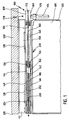
- the parallel pull-out version 100 comprises on both sides of the insert 106 between each side wall 108 of the insert 106 and an inner wall of the body 102 Pull-out guides 110, of which the one in FIGS the pull-out guide 104 arranged on the right 104 is shown.
- Pull-out guides 110 are mirror images of those on the right arranged pull-out guide 110 formed and arranged.
- each pull-out guide comprises 110 a substantially U-shaped support rail 112 which one has long leg 114 and a short leg 116, the holding rail 112 with the long leg 114 on the The inner wall of the body 102 is fixed and the short leg the holding rail 112 has a body-side guide rail 118 with a substantially C-shaped cross section.
- the open one Side of the cabinet side guide rail 118 is to the side wall 108 of the insert 106 directed.
- a middle guide rail 120 is arranged, which also has a substantially C-shaped cross section and on the body-side guide rail 118 by means of between the legs of the middle guide rail 120 and the body-side guide rail 118 arranged rolling elements, preferably guided by balls 122. Even the middle one Guide rail 120 is with its open side to the side wall 108 of the insert 106 directed towards.
- the central guide rail 120 Is between the legs of the central guide rail 120 a slide-in guide rail 124 arranged, the also has a substantially C-shaped cross section and by means of between the legs of the insertion side Guide rail 124 and the middle guide rail 120 arranged Rolling elements, preferably by means of balls 126 the middle guide rail 120 is guided.
- the insert side Guide rail 124 is closed with its open side the middle guide rail 120 directed and on her the middle guide rail 120 facing away from the Side wall 108 of insert 106 fixed.
- the body-side guide rail 118 carries on the top of its upper leg an essentially cuboid, next to the side wall 108 of the insert 106 along the Pull-out direction 104 extending base part 130 of the parallel pull-out version 100.
- the base part 130 is on the body-side guide rail 118 provided retaining tabs 134 and 136 as well the base part 130 provided holding tabs 138 with the body side Guide rail 118 clamped.
- the base part 130 comprises one in the pull-out direction 104 rear area 140 and one in the pull-out direction 104 front area 142, the front its top is a substantially cuboid, itself along the extension direction 104 from a front of the base part 130 rearwardly extending guide recess 144 having.
- the guide recess 144 becomes the insert 106 side through an inner guide leg 146 and to the side of the body 102 through an outer guide leg 148 of the front region 142 of the base part 130.
- the sides facing the insert 106 are as follows the elements of the parallel pull-out version 100 as the inside thereof, the sides of these elements facing the body 102 referred to as their outsides. Furthermore, the following the front in the pull-out direction 104 of the Elements of the parallel pull-out version 100 as their front sides, the sides lying in the pull-out direction 104 of these elements referred to as their back sides or back sides.
- a rear area of the guide recess 144 opens towards the top of the cabinet-side guide rail 118 while a front area of the guide recess 144 bounded downward by a guide projection 150 is that between the inner guide leg 146 and the outer guide leg 148 of the base part 130 along the Extending direction 104 from the front of the base part 130 extends backwards and from the inner guide leg 146 and the outer guide leg 148 is worn.
- a front end of the guide projection 150 engages front end of the body-side guide rail 118 and has on its front a perpendicular to the direction of extension 104 aligned front stop surface 152.
- a rear end of the guide projection 150 also has one substantially perpendicular to the pull-out direction 104 aligned rear stop surface 154.
- the rear region 140 of the base part 130 is on it Top with a close to the inner edge of the top inner extending along the pull-out direction 104 Row of teeth 156 and one parallel to the inner row of teeth 156 near the outer edge of the top of the base part 130 extending along the pull-out direction 104 Row of teeth 158 provided. For the sake of clarity are not all teeth of rows of teeth 156 in the drawings and 158.
- a guide groove 160 along the pull-out direction 104 from the guide recess 144 to a rear End of base 130.
- the inner guide leg 146 is on its top an inner partial row of teeth 162 provided that the front End of the inner row of teeth 156 and the same Front of the base part 130 continues.
- outer guide leg 148 is on its top with an outer row of teeth 164 provided on the front end of the outer row of teeth 158 connects and continues to the front of the base 130.
- the width of the inner row of teeth 162 and the outer Partial row of teeth 164 is slightly less than half that Width of the inner row of teeth 156 or the outer row of teeth 158.
- the teeth of the inner row of teeth 156 are opposite the teeth the outer row of teeth 158 in the pull-out direction 104 by one half tooth spacing.
- the teeth are corresponding the inner partial tooth row 162 with respect to the teeth of the outer Partial row of teeth 164 in the pull-out direction 104 by one half tooth spacing.
- the inner ring gear 166 is opposite the outer one Ring gear 168 in the circumferential direction of the double gear 170 um half a tooth spacing to a simultaneous Engagement of the double gear 170 in the inner row of teeth 156 and to enable the outer row of teeth 158 of the base part 130.
- a coaxial guide disk 172 is arranged with the same, which extends in a radial direction to the tips of the Teeth of sprockets 166 and 168 extend and into the guide groove 160 between the inner row of teeth 156 and the outer Row of teeth 158 of the base part 130 engages.
- This Guide disc 172 is prevented that the double gear 170 during rolling on tooth rows 156 and 158 moved perpendicular to the pull-out direction 104. This ensures that the sprockets 166 and 168 of the double gear 170 always in engagement with the rows of teeth 156 and 158 of the base part 130.
- the double gear 170 arranged on the right of the insert 106 is arranged with a corresponding one on the left of the insert 106 Double gear (not shown in the drawings) 170 by means of a common synchronization shaft 174, which carries both double gears 170, rigidly connected.
- the Synchronization shaft 174 is mounted in bearing brackets 176, which are fixed to the insert 106.
- the guide recess takes 144 of the front portion 142 of the base part 130 in the inserted state of the parallel extension guide 100 an essentially cuboidal extension part 180, that when inserted with its inside on the inner guide leg 146 and with its outside on the outer guide leg 148 abuts and with its underside rests on the top of the guide projection 150.
- This position of the extension part 180 is as follows referred to as its insertion position.
- the extension member 180 carries at the front edge of it Underside of a downward projecting stop lug 182, the Back of a front stop surface 184 of the extension part 180 forms.
- the extension part 180 also has at the rear edge on its underside a rear stop nose protruding downwards 186 on, the front of a rear stop surface 188 of the extension part 180 forms.
- the extension part 180 carries one on its rear side hooks projecting rearward along the pull-out direction 104 190, in which a hook-shaped end 192 of a tension coil spring 194 is mounted.
- the tension coil spring 194 extends along the extension direction 104 by one on the underside of the rear region 140 of the base part 130 Spring tunnel 196 and is hook-shaped on a rear End 198 hung on a retaining pin 200 that is vertical to the pull-out direction 104 through the spring tunnel 196 extends and held on the side walls of the spring tunnel 196 is.
- the extension part 180 is on its top with a the inner partial tooth row adjacent to the inner edge of this upper side 202 and one adjacent to the outer edge of this top outer row of teeth 204 provided.
- the two Part tooth rows 202 and 204 of the extension part 180 extend parallel to each other along the direction of extension 104 and are in the pull-out direction 104 by half a tooth spacing offset against each other.
- a guide groove 206 which the partial rows of teeth 202 and 204 separates from each other.
- the width of the inner part tooth row 202 and the outer Partial tooth row 204 of the extension part 180 is in each case just over half the width of the inner row of teeth 156 or the outer row of teeth 158 of the base part 130. Die Width of the inner part tooth row 202 and the outer part tooth row 204 of the extension part 180 corresponds together with the width of the inner row of teeth 162 or the outer Partial tooth row 164 of the inner guide leg 146 or of the outer guide leg 148 the width of the inner Row of teeth 156 or the outer row of teeth 158 of the base part 130.
- the inner side wall of the extension part facing the insert 106 180 and the outer body 102 facing Side wall of the extension part 180 are each one Passes through slot 208, which opens into the guide groove 206 and extends along the extension direction 104 (see FIG. 2).
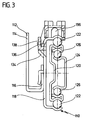
- each of the slots 208 there is a locking lever 210 by means of one pivot pin 212 each perpendicular to the Extension direction 104 and perpendicular to the top of the extension part 180 pivot axis 214 pivotable stored (see Fig. 4).
- Each of the detent levers 210 includes one in the extending direction 104 arranged in front of the pivot axis 214 locking arm 216 and one in the pull-out direction 104 behind the pivot axis 214 arranged rear guide arm 218.
- the locking arms 216 of the pair of locking levers 210 each carry one protruding toward the other locking lever 210 front stop nose 220 and one from the other Locking lever 210 away locking lug 222.
- the facing each other Side faces of the front stop lugs 220 of the two Latch levers 210 serve as front stop surfaces 224 which in the insertion position of the extension part shown in FIG. 4 180 lie against each other.
- the backs of the front Stop lugs 220 each form a driving surface 226, the insertion position shown in Fig. 4 on the front one in the guide groove 206 of the extension part 180 engaging on the side wall 108 of the insert 106 fixed driver 228 is present.
- the side surfaces of the locking lugs 222 facing away from one another Latch levers 210 serve as front guide surfaces 230, which in the insertion position shown in Fig. 4 on the outside of the inner guide leg 146 or on the inside of the outer guide leg 148 of the base part 130 issue.
- the rear sides of the locking lugs 222 serve as locking surfaces 232, as will be explained in more detail below.
- the guide arms 218 of the pair of locking levers 210 each carry one protruding toward the respective other locking lever 210 rear stop lug 234.
- the mutually facing side surfaces the rear stop lugs 234, the locking lever 210 form rear abutment surfaces 236.
- the side surfaces of the guide arms 218 facing away from one another the locking lever 210 serve as rear guide surfaces 238, the in the insertion position shown in Fig. 4 on the outside of the inner guide leg 146 or on the inside of the outer guide leg 148 of the base part 130 issue.
- the base parts arranged to the left and right of the insert 106 130 and extension parts 180 form together second parallel guide element 239 of the parallel extension guide 100.
- the extension part is in the state of the parallel pull-out version 100 180 in its insertion position, in which the front stop surface 184 of the front stop nose 182 des Displacement part 180 on the front stop surface 152 of the Guide projection 150 of the base part 130 abuts.
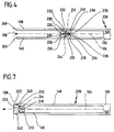
- the insert 106 If the insert 106 is pulled out of the body in the pull-out direction 104 102 is pulled out, it moves on the insert 106 fixed driver 228 due to the contact with the in the direction of movement of the driver 228 in front of the same driving surfaces 226 the locking lever 210 the extension part 180 along the pull-out direction 104 from the guide recess 144 of the base part 130 out.
- extension part 180 is the same as that shown in FIGS to 7 position shown, the following as its extension position is reached, the front stand Stop lugs 220 of the locking lever 210 over the front Ends of the guide legs 146 and 148, so that now the locking lever 210 is pivoted about the respective pivot axis 214 and the driving surfaces 226 from the path of the driver 228 can be removed, especially in FIG. 7 is clearly visible.
- extension part 180 In this extended position of the extension part 180 are the locking surfaces 232 of the locking lugs 222 of the locking lever 210 on the front sides of the inner guide leg 146 and the outer guide leg 148 and thus prevent the extension part 180 by the tensile force of the tension coil spring 194 in the insertion position is moved back.
- the extension part 180 is thus in the extension position through the cooperation of the Lugs 222 and the locking surfaces 240 with the base part 130 locked.
- extension part 180 does not move more with the driver 228, but remains in its Extension position in which the rear stop surface 188 of the rear stop lug 186 of the extension part 180 on the rear stop surface 154 of the guide projection 150 of the base part 130 abuts.
- Double gear 170 at the beginning of the extraction process first on the rows of teeth 156 and 158 of the rear area 140 of the base part 130, then on the partial tooth rows 162 and 164 of the front area 142 of the base part 130 and finally on the partial tooth rows 202 and 204 of the extension part 180 rolls, in the pull-out direction 104 over the Front 128 of the body 102 are moved out so that a complete extension of the insert 106 from the body 102 is possible.
- each comprehensive second parallel guide element 239 always parallel to the pull-out direction 104 is an exact one Parallel guidance of a very wide slide-in 106 for Pulling out of the body 102 or when pushing it into the same guaranteed.
- the driver 228 runs into the intermediate space between the locking levers 210 and presses the guide arms 218 apart, so that the locking lever 210 around the respective pivot axis 214 are pivoted and the locking surfaces 232 no longer rest against the blocking surfaces 240.
- the extension part 180 is unlocked and is by the tension coil spring 194 backwards into the guide recess 144 pulled in until the front stop surface 184 of the front Stop lug 182 of the extension part 180 in the insertion position of the extension part 180 again at the front Stop surface 152 of the guide projection 150 of the base part 130 is present.
- the double gear wheel rolls 170 first over the partial tooth rows 202 and 204 of the extension part 180, then over the partial rows of teeth 162 and 164 of the front area 142 of the base part 130 and finally over the back rows 156 and 158 140 of the base part 130.
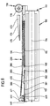
- a second embodiment shown in Figures 8 to 12 a parallel pull-out version 100 differs from the first embodiment described above only with regard to the design of the extension part and Driver and in that an additional return driver is provided for the extension part.
- the extension part shown in Fig. 8 in its insertion position 380 of the second embodiment essentially the shape of a wedge that opposes the Pull-out direction 104 tapers.
- the extension part 380 In the insertion position the extension part 380 with a front area 381 of it Bottom side on top of the guide projection 150 of the base part 130.
- extension part 180 In a rear area of its underside is the extension part 180 with a substantially along the extension 104 extending latching recess 382 provided, the forward through a substantially perpendicular to the Pull-out direction 104 aligned latching surface 432 and after behind by a likewise essentially perpendicular to the Pull-out direction 104 aligned rear stop surface 388 is limited.
- the bottom 383 of the extension part 380 runs essentially in the area of the recess 382 parallel to the top of the extension part 380.
- the extension part 380 carries a hook on its rear side 390, in which in the context of the first Embodiment described the front hook-shaped End 192 of the tension coil spring 194 is hooked.
- the extension part 380 At its top is the extension part 380 with a the inner partial tooth row adjacent to the inner edge of the upper side 402 and one adjacent to the outer edge of the top outer row of teeth 404 (see Fig. 12).
- the partial tooth rows 402 and 404 run essentially parallel to the pull-out direction 104, but are in the In Fig. 8 inserted position of the extension part 380 at an angle of approximately 5 ° to the horizontal inclined.
- the extension part 380 carries one on its front side Coupling head 444, which is enlarged in FIG. 9 and in one Sectional view in Fig. 10 is shown.
- the coupling head has on its inside and on its outside 444 each have a slide track 446, into each one oriented perpendicular to the pull-out direction 104
- Driver pin 448 which on a on the side wall 108 of the Insert 106 held, shown in Fig. 12 428 is held, can intervene.
- Each slide track 446 has an inlet area that is open to the front 450 for one of the driver pins 448 to which each have a sliding channel running obliquely downwards to the rear 452 connects.
- each shift channel 452 becomes after limited at the front by a driving surface 426. Between the Driving surface 426 and the lower edge of the inlet area 450 extends a front sliding slope 454. A the front sliding bevel 454 opposite side wall of the shift channel 452 forms a rear shift slope 456.
- the coupling head 444 on its inside and on on the outside of each a return recess 458, the below the inlet area 450 of the slide 446 and in the pull-out direction 104 in front of the sliding channel 452 is.
- each return recess 458 In the pull-out direction 104 in front of each return recess 458 is an elastic tongue 460 on the coupling head 444 arranged transversely to the pull-out direction 104 of the Coupling head 444 protrudes from the front of the coupling head 444 seen from the direction of extension 104, covers the associated return recess 458.
- one of the elastic Tongues 460 can be the relevant elastic tongue 460 to the Coupling head 444 are bent so that the path is opposite the pull-out direction 104 into the associated return recess 458 is released.
- One back of each elastic Tab 460 serves as return surface 464, as follows will be explained in more detail.
- the coupling head 444 has at the lower edge of it Front one to the side of the insert 106 or to the On the side of the body 102 protruding stop lug 466, the Back serves as a front stop surface 468.
- the front Stop surfaces 468 act in the insertion position of the extension part 380 with in the front area 142 of the Base part 130 arranged stop surfaces 470 (see Fig. 12) together to follow the movement of the extension member 380 to be restricted at the back against the pull-out direction 104.
- Coupling head 444 also has at the rear edge thereof Top of a transverse to the pull-out direction 104, Return driving surface rising in the direction of extension 104 471, which are so designed and arranged is that it is in the insertion position of the extension part 380 with one in the pull-out direction 104 in front of the Double gear 170 arranged return driver 472 can work together.
- the return driver 472 is fixed to the insert 106 and includes a wedge-shaped support plate 474 which extends in the direction of extension 104 tapers and at the bottom one essentially rectangular, horizontally aligned driver plate 476 is molded.
- the return driver 472 can, for example, on the Insert 106 be fixed that the holding plate 474 and Driver plate 476 on a corner connector 478 of the insert 106, in particular on a corner connector for an insert serving hanging frame, are molded, as in the figures 13 and 14.
- a bracket can also be attached to such a corner connector 478 376 for the synchronization shaft 174 of the double gears 170 be formed, creating a constant distance between the double gears 170 and the respective return drivers 472 is guaranteed.
- the return driver 472 serves the extension part 380 to be returned from the inserted position to the extended position, if the extension part 380 is at partial pulled-out insert 106 unintentionally from the Extended position has moved into the insertion position, such as will be explained in more detail below.
- the return driver 472 covers one in the pull-out direction 104 in front of the double gear 170 Area of the rows of teeth 156 and 158 of the base part 130, the Partial tooth rows 162 and 164 of the base part 130 or the partial tooth rows 402 and 404 of the extension part 380 and prevented so that when pulling out or pushing in the insert 106 any objects between the sprockets 166 and 168 of the double gear 170 on the one hand and the aforementioned Rows of teeth on the other hand.
- the Return driver 472 of the second embodiment at the same time as a cover apron for the double gear 170.
- the second embodiment of a parallel pull-out design is correct 100 in terms of its structure with the above described first embodiment match, so far reference to the description of the first embodiment is taken.
- Extension part 380 In the inserted state shown in FIG Parallel extension version 100 is the extension part 380 in its retracted position, in which the front stop surfaces 468 of the stop lugs 466 of the coupling head 444 abut the stop surfaces 470 of the base part 130 and the Bottom of the extension part 380 on top of the Guide projection 150 of the base part 130 rests.
- the drawer 106 moves forward in the pull-out direction 104 extended, the driver 428 also moves in the pull-out direction 104 and leads the extension part 380 against the tensile force of the tension coil spring 194 with it, since the driving surfaces 426 of the shift channels 452 in the direction of movement lie in front of the driver pin 448.
- the driver 428 extends the extension part 380 so far the guide recess 144 of the base part 130 is pulled out has that the front portion 381 of the bottom of the extension part 380 no longer in contact with the top of the Guide projection 150 of the base part 130 is pivoted Extension part 380 by a perpendicular to the direction of extension 104 passing through the rear edge of its underside Swivel axis down until the bottom 383 of the Extension part 380 in the area of the recess 382 the top of the guide protrusion 150 of the base part 130 rests and the locking surface 432 on the locking surface 440 serving front of the guide projection 150 of the base part 130 is present.
- This position is the extension position of the extension part 380 of the second embodiment the parallel extension version 100.
- the partial rows of teeth run in this extended position 402 and 404 of the extension part 380 horizontally, so that the Double gear 170 can roll on these partial rows of teeth.
- extension part 380 Due to environmental influences, such as vibrations or unwanted Touching the extension part 380, however, can occur that the extension part 380 unintentionally unlocked and then due to the tension of the tension coil spring 194 is moved into the insertion position without the Driver pin 448 engages with the sliding channels 452 stand.
- extension part 380 must first be brought back into the extension position before a Slide the insert 106 back into the end insert position can be done.
- the insert 106 is inserted until the driver pins 448 the front sides 462 of the elastic Tongues 460 of the coupling head 444 reach them to the side Press and get into the return recesses 458.
- the extension part swivels 380 in the manner described above below, with the driver pin 448 relative to the Coupling head 444 along the return surfaces 464 of the elastic Tongues 460 up over the top of the elastic Move tongues 460 out of the return recesses 458, so that the driver pin 448 then can move forward along the extension direction 104, without taking the extension part 380 with it.
- the insert 106 can be used again fully inserted.
- extension member 380 When the extension member 380 is in a partially extended State of the parallel pull-out version 100, in which the Return driver 472 in the pull-out direction 104 behind the Coupling head 444 of the extension part 380 is located, unintentionally unlocked and due to the tension of the tension coil spring 194 is moved into the insertion position, so it can Extension part 380 alternatively to that described above Procedure also using the return driver 472 be brought back into the extended position.
- the insert 106 and thus the return driver 472 moved forward in the pull-out direction 104 until the front the driver plate 476 of the return driver 472 with the return driving surface 471 of the coupling head 444 of the extension part 380 is in contact. If continued Forward movement of the return driver 472 along the Extending direction 104, the extension part 380 of the Return driver 472 pulled until the extension part 380 when reaching the extension position in the above described pivots downward, the driver plate 476 relative to the coupling head 444 along the Return driving area 471 up over the top of the Coupling head 444 moves out so that the return driver 471 then continue along the pull-out direction 104 can move forward without the extension 380 to take with you.
- the insert 106 can be used again fully inserted.
- the distance between the front of the drive plate 476 and the axis of rotation of the double gear 170 is at least as large as the distance between the return take-along area 471 and the rear end of the partial tooth rows 402 and 404 of the extension part 380, so that the double gear 170 with the extension part in the insertion position Move 380 far enough in the direction of extension 104 can to get the return driver 472 in contact with the Bring return driving surface 471 without the rolling motion of the double gear 170 through the (in the inserted position of the extension part 380 inclined to the horizontal) Part tooth rows 402 and 404 of the extension part 380 is hindered.
- the driver pins run when the insert 106 is inserted 448 through the inlet areas 450 against the respective rear Slope 456 of the shift channels 452, whereby the extension part 380 is pivoted upwards so that the locking surface 432 no longer the locking surface 440 of the base part 130 faces and thus the extension part 380 is unlocked.
- the unlocked extension part 380 is due to the tensile force the tension coil spring 194 along the extension direction 104 pulled back until the front stop surfaces 468 of the Stop lugs 466 on the stop surfaces 470 of the base part 130 concerns.
- the driver pin 448 in the direction of movement of the extension part 380 in front of the driving surfaces 426 of the shift channels 452 are arranged, the driver pins 448 and thus the driver 428 and the one connected to it Insert 106 pulled by the extension part 380 so that the insert 106 via a feed path which is the same as that during the movement of the extension part 380 from the insertion position in the extended position corresponds to the distance covered, is pulled into the end insertion position.
- the one spent Energy corresponds to the energy that is needed when pulling out the Insert 106 was stored in the tension coil spring 194.
- the second embodiment of a parallel pull-out design is correct 100 in terms of their function with the above described first embodiment match, so far reference to the description of the first embodiment is taken.
Landscapes
- Bearings For Parts Moving Linearly (AREA)
- Toys (AREA)
- Surface Acoustic Wave Elements And Circuit Networks Thereof (AREA)
- Optical Integrated Circuits (AREA)
- Mechanical Coupling Of Light Guides (AREA)
- Buckles (AREA)
- Particle Accelerators (AREA)
- Advance Control (AREA)
- Crystals, And After-Treatments Of Crystals (AREA)
Applications Claiming Priority (2)
| Application Number | Priority Date | Filing Date | Title |
|---|---|---|---|
| DE19718069 | 1997-04-29 | ||
| DE19718069A DE19718069C1 (de) | 1997-04-29 | 1997-04-29 | Parallelauszugführung |
Publications (3)
| Publication Number | Publication Date |
|---|---|
| EP0875178A2 true EP0875178A2 (fr) | 1998-11-04 |
| EP0875178A3 EP0875178A3 (fr) | 1999-11-24 |
| EP0875178B1 EP0875178B1 (fr) | 2003-01-02 |
Family
ID=7828098
Family Applications (1)
| Application Number | Title | Priority Date | Filing Date |
|---|---|---|---|
| EP98104106A Expired - Lifetime EP0875178B1 (fr) | 1997-04-29 | 1998-03-07 | Glissière pour tiroir parallèle |
Country Status (5)
| Country | Link |
|---|---|
| EP (1) | EP0875178B1 (fr) |
| AT (1) | ATE230230T1 (fr) |
| DE (2) | DE19718069C1 (fr) |
| DK (1) | DK0875178T3 (fr) |
| ES (1) | ES2189998T3 (fr) |
Cited By (2)
| Publication number | Priority date | Publication date | Assignee | Title |
|---|---|---|---|---|
| EP1574151A2 (fr) | 1999-03-17 | 2005-09-14 | Julius Blum GmbH | Dispositif pour la stabilisation du comportement d'un tiroir déplaçable dans un corps de meuble |
| DE202015100356U1 (de) | 2015-01-27 | 2015-02-05 | Anton Schneider Gmbh & Co Kg | Parallelauszugführung |
Families Citing this family (3)
| Publication number | Priority date | Publication date | Assignee | Title |
|---|---|---|---|---|
| DE19944645A1 (de) * | 1999-09-17 | 2001-03-29 | Schock Metallwerk | Auszugführung |
| DE29923657U1 (de) * | 1999-09-17 | 2001-01-18 | Schock Metallwerk Gmbh, 73660 Urbach | Auszugführung |
| AT526737B1 (de) * | 2022-12-02 | 2025-11-15 | Blum Gmbh Julius | Verfahren zur Herstellung wenigstens einer Bauteilkomponente für einen Möbelbeschlag |
Citations (1)
| Publication number | Priority date | Publication date | Assignee | Title |
|---|---|---|---|---|
| EP0512615A1 (fr) | 1991-05-02 | 1992-11-11 | Thomas Regout N.V. | Système d'anti-fléchissement pour le guidage de tiroirs |
Family Cites Families (6)
| Publication number | Priority date | Publication date | Assignee | Title |
|---|---|---|---|---|
| US1758550A (en) * | 1925-12-05 | 1930-05-13 | Remington Rand Inc | Supporting means for drawers for articles of furniture |
| GB321421A (en) * | 1928-05-08 | 1929-11-08 | Doehler Die Casting Co | Improvements in or relating to drawers and supports or guides therefor |
| US4324439A (en) * | 1980-01-10 | 1982-04-13 | Standard Precision, Inc. | Anti-rack system for wide drawers and the like |
| DE8900914U1 (de) * | 1989-01-27 | 1989-03-09 | Häfele KG, 7270 Nagold | Auszug |
| JPH0428307A (ja) * | 1990-05-23 | 1992-01-30 | Sugatsune Ind Co Ltd | 部材の走行制御装置 |
| IT1277526B1 (it) * | 1995-08-31 | 1997-11-10 | Schiffini Mobili Cucine Spa | Struttura di cassetto ad elevata precisione di scorrimento per componenti d'arredamento |
-
1997
- 1997-04-29 DE DE19718069A patent/DE19718069C1/de not_active Expired - Fee Related
-
1998
- 1998-03-07 EP EP98104106A patent/EP0875178B1/fr not_active Expired - Lifetime
- 1998-03-07 DK DK98104106T patent/DK0875178T3/da active
- 1998-03-07 AT AT98104106T patent/ATE230230T1/de active
- 1998-03-07 ES ES98104106T patent/ES2189998T3/es not_active Expired - Lifetime
- 1998-03-07 DE DE59806779T patent/DE59806779D1/de not_active Expired - Lifetime
Patent Citations (1)
| Publication number | Priority date | Publication date | Assignee | Title |
|---|---|---|---|---|
| EP0512615A1 (fr) | 1991-05-02 | 1992-11-11 | Thomas Regout N.V. | Système d'anti-fléchissement pour le guidage de tiroirs |
Cited By (4)
| Publication number | Priority date | Publication date | Assignee | Title |
|---|---|---|---|---|
| EP1574151A2 (fr) | 1999-03-17 | 2005-09-14 | Julius Blum GmbH | Dispositif pour la stabilisation du comportement d'un tiroir déplaçable dans un corps de meuble |
| EP1574151A3 (fr) * | 1999-03-17 | 2006-08-16 | Julius Blum GmbH | Dispositif pour la stabilisation du comportement d'un tiroir déplaçable dans un corps de meuble |
| DE202015100356U1 (de) | 2015-01-27 | 2015-02-05 | Anton Schneider Gmbh & Co Kg | Parallelauszugführung |
| EP3050463A1 (fr) | 2015-01-27 | 2016-08-03 | Anton Schneider GmbH & Co KG | Guide telescopique parallele |
Also Published As
| Publication number | Publication date |
|---|---|
| ES2189998T3 (es) | 2003-07-16 |
| EP0875178A3 (fr) | 1999-11-24 |
| DE19718069C1 (de) | 1998-05-28 |
| DK0875178T3 (da) | 2003-02-24 |
| ATE230230T1 (de) | 2003-01-15 |
| EP0875178B1 (fr) | 2003-01-02 |
| DE59806779D1 (de) | 2003-02-06 |
Similar Documents
| Publication | Publication Date | Title |
|---|---|---|
| EP0391221B1 (fr) | Dispositif pour fermer de tiroirs | |
| EP2770876B1 (fr) | Verrouillage synchronisé pour une partie mobile de meuble | |
| DE3836273C2 (de) | Synchronisierte dreigliedrige Teleskopschiene für Zugglieder | |
| DE9413108U1 (de) | Schubladenführung | |
| EP1820422B1 (fr) | Système de guidage de coulissement pour parties de meuble qui peuvent coulisser hors du corps d'un meuble | |
| DE2941126A1 (de) | Zum schutz eines maschinenbettes bestimmte abdeckung | |
| EP1110481A1 (fr) | Accessoire pour l'extraction complète de tiroirs et couplage | |
| EP1858369B1 (fr) | Dispositif destine a recevoir un tiroir | |
| AT516222A1 (de) | Ausziehführung | |
| AT413473B (de) | Selbsteinzugvorrichtung | |
| EP0875178B1 (fr) | Glissière pour tiroir parallèle | |
| DE3834688A1 (de) | Synchronisierte vollauszugfuehrung | |
| EP3498131B1 (fr) | Guidage d'extraction | |
| EP4217562B1 (fr) | Dispositif de blocage d'extraction pour tiroirs | |
| DE3643779A1 (de) | Geraet zum aufnehmen und/oder wiedergeben von signalen auf informationsplatten mit einem lichtoptischen einschreibe- und/oder ausleseaggregat (auto-cd-spieler) | |
| EP2046164A2 (fr) | Glissière de sortie pour guider des parties de meubles | |
| EP1649782B1 (fr) | Glissières pour tiroirs | |
| EP3745916B1 (fr) | Agencement de rails de guidage, dispositif de synchronisation de rail et actuateur | |
| EP0639687B1 (fr) | Glissière | |
| EP0780645B1 (fr) | Compartiment d'emmagasinage en forme de tiroir | |
| DE202004001998U1 (de) | Ausziehsperreinrichtung | |
| DE3313122C2 (de) | Schutzabdeckung für Führungsbahnen von Werkzeugmaschinen | |
| DE3412072A1 (de) | Schrank, insbesondere registraturschrank, mit mehreren uebereinander angeordneten schubladen | |
| EP0523424B1 (fr) | Dispositif de guidage pour tiroir | |
| EP0546201A1 (fr) | Glissière pour tiroirs |
Legal Events
| Date | Code | Title | Description |
|---|---|---|---|
| PUAI | Public reference made under article 153(3) epc to a published international application that has entered the european phase |
Free format text: ORIGINAL CODE: 0009012 |
|
| AK | Designated contracting states |
Kind code of ref document: A2 Designated state(s): AT BE CH DE DK ES FR GB IT LI NL SE |
|
| AX | Request for extension of the european patent |
Free format text: AL;LT;LV;MK;RO;SI |
|
| PUAL | Search report despatched |
Free format text: ORIGINAL CODE: 0009013 |
|
| AK | Designated contracting states |
Kind code of ref document: A3 Designated state(s): AT BE CH DE DK ES FI FR GB GR IE IT LI LU MC NL PT |
|
| AX | Request for extension of the european patent |
Free format text: AL;LT;LV;MK;RO;SI |
|
| 17P | Request for examination filed |
Effective date: 19991223 |
|
| AKX | Designation fees paid |
Free format text: AT BE CH DE DK ES FR GB IT LI NL SE |
|
| GRAG | Despatch of communication of intention to grant |
Free format text: ORIGINAL CODE: EPIDOS AGRA |
|
| 17Q | First examination report despatched |
Effective date: 20020322 |
|
| GRAG | Despatch of communication of intention to grant |
Free format text: ORIGINAL CODE: EPIDOS AGRA |
|
| GRAH | Despatch of communication of intention to grant a patent |
Free format text: ORIGINAL CODE: EPIDOS IGRA |
|
| GRAH | Despatch of communication of intention to grant a patent |
Free format text: ORIGINAL CODE: EPIDOS IGRA |
|
| GRAA | (expected) grant |
Free format text: ORIGINAL CODE: 0009210 |
|
| AK | Designated contracting states |
Kind code of ref document: B1 Designated state(s): AT BE CH DE DK ES FR GB IT LI NL SE |
|
| REF | Corresponds to: |
Ref document number: 230230 Country of ref document: AT Date of ref document: 20030115 Kind code of ref document: T |
|
| REG | Reference to a national code |
Ref country code: GB Ref legal event code: FG4D Free format text: 20030102:NOT ENGLISH |
|
| REG | Reference to a national code |
Ref country code: CH Ref legal event code: EP |
|
| REG | Reference to a national code |
Ref country code: CH Ref legal event code: NV Representative=s name: ISLER & PEDRAZZINI AG |
|
| REF | Corresponds to: |
Ref document number: 59806779 Country of ref document: DE Date of ref document: 20030206 Kind code of ref document: P |
|
| REG | Reference to a national code |
Ref country code: DK Ref legal event code: T3 |
|
| GBT | Gb: translation of ep patent filed (gb section 77(6)(a)/1977) |
Effective date: 20030324 |
|
| REG | Reference to a national code |
Ref country code: ES Ref legal event code: FG2A Ref document number: 2189998 Country of ref document: ES Kind code of ref document: T3 |
|
| ET | Fr: translation filed | ||
| PLBE | No opposition filed within time limit |
Free format text: ORIGINAL CODE: 0009261 |
|
| STAA | Information on the status of an ep patent application or granted ep patent |
Free format text: STATUS: NO OPPOSITION FILED WITHIN TIME LIMIT |
|
| 26N | No opposition filed |
Effective date: 20031003 |
|
| PGFP | Annual fee paid to national office [announced via postgrant information from national office to epo] |
Ref country code: FR Payment date: 20041221 Year of fee payment: 8 |
|
| PGFP | Annual fee paid to national office [announced via postgrant information from national office to epo] |
Ref country code: GB Payment date: 20041222 Year of fee payment: 8 |
|
| PGFP | Annual fee paid to national office [announced via postgrant information from national office to epo] |
Ref country code: ES Payment date: 20050113 Year of fee payment: 8 |
|
| PGFP | Annual fee paid to national office [announced via postgrant information from national office to epo] |
Ref country code: BE Payment date: 20050125 Year of fee payment: 8 |
|
| PGFP | Annual fee paid to national office [announced via postgrant information from national office to epo] |
Ref country code: SE Payment date: 20050311 Year of fee payment: 8 |
|
| PGFP | Annual fee paid to national office [announced via postgrant information from national office to epo] |
Ref country code: DK Payment date: 20050314 Year of fee payment: 8 |
|
| PGFP | Annual fee paid to national office [announced via postgrant information from national office to epo] |
Ref country code: NL Payment date: 20050331 Year of fee payment: 8 |
|
| PG25 | Lapsed in a contracting state [announced via postgrant information from national office to epo] |
Ref country code: GB Free format text: LAPSE BECAUSE OF NON-PAYMENT OF DUE FEES Effective date: 20060307 |
|
| PG25 | Lapsed in a contracting state [announced via postgrant information from national office to epo] |
Ref country code: SE Free format text: LAPSE BECAUSE OF NON-PAYMENT OF DUE FEES Effective date: 20060308 Ref country code: ES Free format text: LAPSE BECAUSE OF NON-PAYMENT OF DUE FEES Effective date: 20060308 |
|
| PG25 | Lapsed in a contracting state [announced via postgrant information from national office to epo] |
Ref country code: DK Free format text: LAPSE BECAUSE OF NON-PAYMENT OF DUE FEES Effective date: 20060331 Ref country code: BE Free format text: LAPSE BECAUSE OF NON-PAYMENT OF DUE FEES Effective date: 20060331 |
|
| PGFP | Annual fee paid to national office [announced via postgrant information from national office to epo] |
Ref country code: IT Payment date: 20060331 Year of fee payment: 9 |
|
| PG25 | Lapsed in a contracting state [announced via postgrant information from national office to epo] |
Ref country code: NL Free format text: LAPSE BECAUSE OF NON-PAYMENT OF DUE FEES Effective date: 20061001 |
|
| REG | Reference to a national code |
Ref country code: DK Ref legal event code: EBP |
|
| EUG | Se: european patent has lapsed | ||
| GBPC | Gb: european patent ceased through non-payment of renewal fee |
Effective date: 20060307 |
|
| NLV4 | Nl: lapsed or anulled due to non-payment of the annual fee |
Effective date: 20061001 |
|
| REG | Reference to a national code |
Ref country code: FR Ref legal event code: ST Effective date: 20061130 |
|
| REG | Reference to a national code |
Ref country code: ES Ref legal event code: FD2A Effective date: 20060308 |
|
| REG | Reference to a national code |
Ref country code: CH Ref legal event code: PCAR Free format text: ISLER & PEDRAZZINI AG;POSTFACH 1772;8027 ZUERICH (CH) |
|
| BERE | Be: lapsed |
Owner name: *SCHOCK METALLWERK G.M.B.H. Effective date: 20060331 |
|
| PG25 | Lapsed in a contracting state [announced via postgrant information from national office to epo] |
Ref country code: FR Free format text: LAPSE BECAUSE OF NON-PAYMENT OF DUE FEES Effective date: 20060331 |
|
| PG25 | Lapsed in a contracting state [announced via postgrant information from national office to epo] |
Ref country code: IT Free format text: LAPSE BECAUSE OF NON-PAYMENT OF DUE FEES Effective date: 20070307 |
|
| PGFP | Annual fee paid to national office [announced via postgrant information from national office to epo] |
Ref country code: CH Payment date: 20140903 Year of fee payment: 17 |
|
| PGFP | Annual fee paid to national office [announced via postgrant information from national office to epo] |
Ref country code: AT Payment date: 20140908 Year of fee payment: 17 |
|
| REG | Reference to a national code |
Ref country code: DE Ref legal event code: R082 Ref document number: 59806779 Country of ref document: DE Representative=s name: HOEGER, STELLRECHT & PARTNER PATENTANWAELTE MB, DE |
|
| REG | Reference to a national code |
Ref country code: CH Ref legal event code: PL |
|
| REG | Reference to a national code |
Ref country code: AT Ref legal event code: MM01 Ref document number: 230230 Country of ref document: AT Kind code of ref document: T Effective date: 20150307 |
|
| PG25 | Lapsed in a contracting state [announced via postgrant information from national office to epo] |
Ref country code: CH Free format text: LAPSE BECAUSE OF NON-PAYMENT OF DUE FEES Effective date: 20150331 Ref country code: LI Free format text: LAPSE BECAUSE OF NON-PAYMENT OF DUE FEES Effective date: 20150331 |
|
| PG25 | Lapsed in a contracting state [announced via postgrant information from national office to epo] |
Ref country code: AT Free format text: LAPSE BECAUSE OF NON-PAYMENT OF DUE FEES Effective date: 20150307 |
|
| PGFP | Annual fee paid to national office [announced via postgrant information from national office to epo] |
Ref country code: DE Payment date: 20160427 Year of fee payment: 19 |
|
| REG | Reference to a national code |
Ref country code: DE Ref legal event code: R079 Ref document number: 59806779 Country of ref document: DE Free format text: PREVIOUS MAIN CLASS: A47B0088100000 Ipc: A47B0088493000 |
|
| REG | Reference to a national code |
Ref country code: DE Ref legal event code: R119 Ref document number: 59806779 Country of ref document: DE |
|
| PG25 | Lapsed in a contracting state [announced via postgrant information from national office to epo] |
Ref country code: DE Free format text: LAPSE BECAUSE OF NON-PAYMENT OF DUE FEES Effective date: 20171003 |