EP0877274A2 - Bildverfolgungssystem und Verfahren und autostereoskopische Anzeigevorrichtung mit Beobachter-Nachführung - Google Patents
Bildverfolgungssystem und Verfahren und autostereoskopische Anzeigevorrichtung mit Beobachter-Nachführung Download PDFInfo
- Publication number
- EP0877274A2 EP0877274A2 EP98302989A EP98302989A EP0877274A2 EP 0877274 A2 EP0877274 A2 EP 0877274A2 EP 98302989 A EP98302989 A EP 98302989A EP 98302989 A EP98302989 A EP 98302989A EP 0877274 A2 EP0877274 A2 EP 0877274A2
- Authority
- EP
- European Patent Office
- Prior art keywords
- image
- target image
- movement
- observer
- images
- Prior art date
- Legal status (The legal status is an assumption and is not a legal conclusion. Google has not performed a legal analysis and makes no representation as to the accuracy of the status listed.)
- Withdrawn
Links
- 238000000034 method Methods 0.000 title claims abstract description 69
- 230000003287 optical effect Effects 0.000 claims description 11
- 230000006870 function Effects 0.000 claims description 8
- 230000007246 mechanism Effects 0.000 abstract description 12
- 210000003128 head Anatomy 0.000 description 23
- 230000004044 response Effects 0.000 description 16
- 238000001514 detection method Methods 0.000 description 15
- 238000010586 diagram Methods 0.000 description 12
- 238000012545 processing Methods 0.000 description 12
- 230000008569 process Effects 0.000 description 11
- 230000004886 head movement Effects 0.000 description 10
- 239000000872 buffer Substances 0.000 description 9
- 230000000694 effects Effects 0.000 description 8
- 238000005286 illumination Methods 0.000 description 8
- 238000012795 verification Methods 0.000 description 6
- 238000005259 measurement Methods 0.000 description 5
- 238000004422 calculation algorithm Methods 0.000 description 4
- 230000008859 change Effects 0.000 description 4
- 238000004891 communication Methods 0.000 description 4
- 230000000875 corresponding effect Effects 0.000 description 4
- 238000004364 calculation method Methods 0.000 description 3
- 230000006835 compression Effects 0.000 description 3
- 238000007906 compression Methods 0.000 description 3
- 230000002452 interceptive effect Effects 0.000 description 3
- XUIMIQQOPSSXEZ-UHFFFAOYSA-N Silicon Chemical compound [Si] XUIMIQQOPSSXEZ-UHFFFAOYSA-N 0.000 description 2
- 238000009825 accumulation Methods 0.000 description 2
- 230000008901 benefit Effects 0.000 description 2
- 230000001276 controlling effect Effects 0.000 description 2
- 230000002596 correlated effect Effects 0.000 description 2
- 230000014509 gene expression Effects 0.000 description 2
- 239000011521 glass Substances 0.000 description 2
- 238000000926 separation method Methods 0.000 description 2
- 229910052710 silicon Inorganic materials 0.000 description 2
- 239000010703 silicon Substances 0.000 description 2
- 238000012360 testing method Methods 0.000 description 2
- 230000000007 visual effect Effects 0.000 description 2
- 206010052143 Ocular discomfort Diseases 0.000 description 1
- 238000012300 Sequence Analysis Methods 0.000 description 1
- 230000003044 adaptive effect Effects 0.000 description 1
- 230000004075 alteration Effects 0.000 description 1
- 238000004458 analytical method Methods 0.000 description 1
- 230000015556 catabolic process Effects 0.000 description 1
- 238000006243 chemical reaction Methods 0.000 description 1
- 239000003086 colorant Substances 0.000 description 1
- 238000012937 correction Methods 0.000 description 1
- 230000007547 defect Effects 0.000 description 1
- 238000006731 degradation reaction Methods 0.000 description 1
- 229910003460 diamond Inorganic materials 0.000 description 1
- 239000010432 diamond Substances 0.000 description 1
- 210000000887 face Anatomy 0.000 description 1
- 230000001815 facial effect Effects 0.000 description 1
- 230000006872 improvement Effects 0.000 description 1
- 239000004973 liquid crystal related substance Substances 0.000 description 1
- 239000003550 marker Substances 0.000 description 1
- 238000012986 modification Methods 0.000 description 1
- 230000004048 modification Effects 0.000 description 1
- 238000012544 monitoring process Methods 0.000 description 1
- 238000003909 pattern recognition Methods 0.000 description 1
- 210000001747 pupil Anatomy 0.000 description 1
- 230000005855 radiation Effects 0.000 description 1
- 230000009467 reduction Effects 0.000 description 1
Images







Classifications
-
- H—ELECTRICITY
- H04—ELECTRIC COMMUNICATION TECHNIQUE
- H04N—PICTORIAL COMMUNICATION, e.g. TELEVISION
- H04N13/00—Stereoscopic video systems; Multi-view video systems; Details thereof
- H04N13/30—Image reproducers
- H04N13/366—Image reproducers using viewer tracking
- H04N13/378—Image reproducers using viewer tracking for tracking rotational head movements around an axis perpendicular to the screen
-
- G—PHYSICS
- G02—OPTICS
- G02B—OPTICAL ELEMENTS, SYSTEMS OR APPARATUS
- G02B30/00—Optical systems or apparatus for producing three-dimensional [3D] effects, e.g. stereoscopic images
- G02B30/20—Optical systems or apparatus for producing three-dimensional [3D] effects, e.g. stereoscopic images by providing first and second parallax images to an observer's left and right eyes
- G02B30/26—Optical systems or apparatus for producing three-dimensional [3D] effects, e.g. stereoscopic images by providing first and second parallax images to an observer's left and right eyes of the autostereoscopic type
-
- H—ELECTRICITY
- H04—ELECTRIC COMMUNICATION TECHNIQUE
- H04N—PICTORIAL COMMUNICATION, e.g. TELEVISION
- H04N13/00—Stereoscopic video systems; Multi-view video systems; Details thereof
- H04N13/30—Image reproducers
- H04N13/366—Image reproducers using viewer tracking
- H04N13/376—Image reproducers using viewer tracking for tracking left-right translational head movements, i.e. lateral movements
-
- H—ELECTRICITY
- H04—ELECTRIC COMMUNICATION TECHNIQUE
- H04N—PICTORIAL COMMUNICATION, e.g. TELEVISION
- H04N13/00—Stereoscopic video systems; Multi-view video systems; Details thereof
- H04N13/30—Image reproducers
- H04N13/366—Image reproducers using viewer tracking
- H04N13/38—Image reproducers using viewer tracking for tracking vertical translational head movements
-
- H—ELECTRICITY
- H04—ELECTRIC COMMUNICATION TECHNIQUE
- H04N—PICTORIAL COMMUNICATION, e.g. TELEVISION
- H04N13/00—Stereoscopic video systems; Multi-view video systems; Details thereof
- H04N13/10—Processing, recording or transmission of stereoscopic or multi-view image signals
-
- H—ELECTRICITY
- H04—ELECTRIC COMMUNICATION TECHNIQUE
- H04N—PICTORIAL COMMUNICATION, e.g. TELEVISION
- H04N13/00—Stereoscopic video systems; Multi-view video systems; Details thereof
- H04N13/10—Processing, recording or transmission of stereoscopic or multi-view image signals
- H04N13/106—Processing image signals
- H04N13/161—Encoding, multiplexing or demultiplexing different image signal components
-
- H—ELECTRICITY
- H04—ELECTRIC COMMUNICATION TECHNIQUE
- H04N—PICTORIAL COMMUNICATION, e.g. TELEVISION
- H04N13/00—Stereoscopic video systems; Multi-view video systems; Details thereof
- H04N13/20—Image signal generators
- H04N13/286—Image signal generators having separate monoscopic and stereoscopic modes
-
- H—ELECTRICITY
- H04—ELECTRIC COMMUNICATION TECHNIQUE
- H04N—PICTORIAL COMMUNICATION, e.g. TELEVISION
- H04N13/00—Stereoscopic video systems; Multi-view video systems; Details thereof
- H04N13/30—Image reproducers
- H04N13/302—Image reproducers for viewing without the aid of special glasses, i.e. using autostereoscopic displays
- H04N13/31—Image reproducers for viewing without the aid of special glasses, i.e. using autostereoscopic displays using parallax barriers
-
- H—ELECTRICITY
- H04—ELECTRIC COMMUNICATION TECHNIQUE
- H04N—PICTORIAL COMMUNICATION, e.g. TELEVISION
- H04N13/00—Stereoscopic video systems; Multi-view video systems; Details thereof
- H04N13/30—Image reproducers
- H04N13/302—Image reproducers for viewing without the aid of special glasses, i.e. using autostereoscopic displays
- H04N13/32—Image reproducers for viewing without the aid of special glasses, i.e. using autostereoscopic displays using arrays of controllable light sources; using moving apertures or moving light sources
-
- H—ELECTRICITY
- H04—ELECTRIC COMMUNICATION TECHNIQUE
- H04N—PICTORIAL COMMUNICATION, e.g. TELEVISION
- H04N13/00—Stereoscopic video systems; Multi-view video systems; Details thereof
- H04N13/30—Image reproducers
- H04N13/327—Calibration thereof
-
- H—ELECTRICITY
- H04—ELECTRIC COMMUNICATION TECHNIQUE
- H04N—PICTORIAL COMMUNICATION, e.g. TELEVISION
- H04N13/00—Stereoscopic video systems; Multi-view video systems; Details thereof
- H04N13/30—Image reproducers
- H04N13/346—Image reproducers using prisms or semi-transparent mirrors
-
- H—ELECTRICITY
- H04—ELECTRIC COMMUNICATION TECHNIQUE
- H04N—PICTORIAL COMMUNICATION, e.g. TELEVISION
- H04N13/00—Stereoscopic video systems; Multi-view video systems; Details thereof
- H04N13/30—Image reproducers
- H04N13/366—Image reproducers using viewer tracking
- H04N13/373—Image reproducers using viewer tracking for tracking forward-backward translational head movements, i.e. longitudinal movements
-
- H—ELECTRICITY
- H04—ELECTRIC COMMUNICATION TECHNIQUE
- H04N—PICTORIAL COMMUNICATION, e.g. TELEVISION
- H04N19/00—Methods or arrangements for coding, decoding, compressing or decompressing digital video signals
- H04N19/50—Methods or arrangements for coding, decoding, compressing or decompressing digital video signals using predictive coding
- H04N19/597—Methods or arrangements for coding, decoding, compressing or decompressing digital video signals using predictive coding specially adapted for multi-view video sequence encoding
Definitions
- the present invention relates to an image tracking system and method.
- the present invention also relates to an observer tracking autostereoscopic display in which such a system and method may be used.
- the system and method may also be used in other applications, such as security surveillance, video and image compression, video conferencing, computer games, driver monitoring, graphical user interfaces, camera auto-focus systems and multimedia.
- FIG. 1 of the accompanying drawings illustrates schematically the basic components of a typical autostereoscopic display.
- the display comprises a display system 1 and a tracking system 2.
- the tracking system 2 comprises a tracking sensor 3 which supplies a sensor signal to a tracking processor 4.
- the tracking processor derives from the sensor signal an observer position data signal which is supplied to a display control processor 5 of the display system 1.
- the processor 5 converts the position data signal into a window steering signal and supplies this to a steering mechanism 6 which cooperates with a display 7 such that an observer 8 can view the display autostereoscopically throughout an extended range of observer positions.
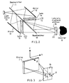
- FIG. 2 of the accompanying drawings illustrates, purely by way of example, part of a display system 1 including the display 7 and the steering mechanism 6.
- the steering mechanism comprises a light source 10 which comprises a linear array of individually controllable light emitting elements.
- a beam splitter 11 such as a partially silvered mirror transmits light from the light source 10 to a mirror 12 and reflects light from the light source 10 to another mirror 13.
- Light reflected by the mirror 12 passes through a lens 14 and is modulated by a spatial light modulator (SLM) in the form of a liquid crystal device (LCD) 15 with the right eye image of a stereoscopic pair.
- SLM spatial light modulator
- LCD liquid crystal device
- a beam combiner 18 for instance in the form of a partially silvered mirror, reflects light from the LCD 15 to a viewing window 19 for the right eye of the observer 8.
- Light from the LCD 17 is transmitted by the beam combiner 18 and forms a viewing window 20 for the left eye of the observer 8.
- the width of each of the viewing windows 19 and 20 is large enough to cover all possible eye separations and typical values of eye separation are from 55 to 70 millimetres.
- the three dimensional (3D) space containing the display 7 and the observer 8 may be described in terms of Cartesian coordinates where X represents the lateral direction, Y represents the vertical direction and Z represents the longitudinal direction.
- diamond-shaped regions 21 and 22 of illumination are formed such that, if the right eye of the observer remains within the region 21 and the left eye of the observer remains with the region 22, a 3D image is perceived across the whole of the display 7.
- These diamond-shaped regions are referred to as viewing zones and are widest at a "best viewing" window plane 23 which contains the viewing windows 19 and 20.
- the viewing zones 21 and 22 illustrate the theoretical longitudinal viewing freedom for the display 7.
- observer tracking and control of the display may be provided.
- the positions of the viewing windows 19 and 20 are "steered" to follow movement of the head of the observer so that the eyes of the observer remain within the appropriate viewing zones.
- An essential part of such a display is the tracking system 2 which locates the position of the head and/or eyes of the observer. In effect, it is generally only necessary to track the centre point between the eyes of the observer because this is the position where the left and right viewing windows meet, as shown in the left part of Figure 4b. Even for relatively large head rotations as shown in the right part of Figure 4b, such a system accurately positions the viewing windows 19 and 20 so as to maintain autostereoscopic viewing.
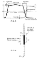
- Each viewing window has a useful viewing region which is characterised by an illumination profile in the plane 23 as illustrated in Figure 5 of the accompanying drawings.
- the horizontal axis represents position in the plane 23 whereas the vertical axis represents illumination intensity.
- the ideal illumination profile would be rectangular with the adjacent window profiles exactly contiguous. However, in practice, this is not achieved.
- the width of the window is taken to be the width of the illumination profile at half the maximum average intensity.
- the profiles of the adjacent viewing windows are not exactly contiguous but have an underlap (as shown) or an overlap. There is variation in uniformity for the "top” of the profile, which represents the useful width. Outside the useful width, the intensity does not fall to zero abruptly but declines steeply to define an edge width. The profile does not reach zero intensity immediately but overlaps with the adjacent profile to give rise to cross talk.
- the differences between the ideal rectangular illumination profile and the actual profile result from a combination of degradation mechanisms including aberrations in optical systems, scatter, defocus, diffraction and geometrical errors in optical elements of the display.
- One of the objects of the tracking system 2 is to keep the eyes of the observer within the best viewing regions at all times.
- the viewing windows 19 and 20 should be able to move continuously. However, in practice, the viewing windows may move in discrete steps between fixed positions.
- the steering mechanism 6 controls the movement or switching of the light source 10 so as to control the viewing window positions. The number of positions and the time required to switch between these positions vary with different displays and steering mechanisms.
- Figure 6 of the accompanying drawings illustrates an example of the range of viewing window positions achievable for a display of the type shown in Figure 2 where the light source 10 comprises fourteen contiguous illuminators and each viewing window has a width determined by four illuminators. This gives rise to eleven possible positions for the viewing window and a typical position is illustrated at 25.
- Each illuminator is imaged to a strip or "step" such as 26 in the window plane 23 having a width of 16 millimetres with four contiguous strips providing a window width of 64 millimetres.
- the tracking system 2 attempts to keep the pupil of the eye of the observer in the middle two strips as illustrated at 27. Before the viewer moves one step laterally away from the centre of the region 27, the tracking system 2 illuminates the next strip 26 in the direction of movement and extinguishes the opposite or trailing strip.
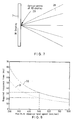
- a typical display 7 provides viewing zones in the shape of cones or wedges, such as 28 as shown in Figure 7 of the accompanying drawings, which emanate from a common origin point referred to as the optical centre 29 of the display.
- the viewing zones determine the positions at which switching must take place whenever the centre of the two eyes of the observer moves from one window position to another.
- the viewing zones are angularly spaced in the horizontal plane specified by the lateral direction (X) and the longitudinal direction (Z) of the observer with respect to the display.
- the observer can move by a distance d equivalent to one step before the system needs to respond and update the window position.
- the actual response time of the tracking and display system includes not only the time required for determining the position of the observer but also the communication time needed to pass this information to the steering mechanism and the time required to switch between the current window position and the next window position.
- the required system response time is further reduced by the accuracy of the tracking system.
- the broken line 31 in Figure 8 illustrates the response time where e is 5 millimetres.
- the required response time is reduced to 22 milliseconds for a maximum head speed of 500 millimetres per second.
- the step size, the measuring error and the system response time should therefore be such as to provide a value of v which meets the desired criterion, for instance of 500 millimetres per second.
- a known type of infrared tracking system based on detecting infrared radiation reflected from a retroreflective spot worn by an observer between his eyes is called the DynaSight sensor and is available from Origin Instruments.
- the 3D coordinates of the retroreflective spot with respect to an infrared sensor are obtained at a rate of up to 64 Hz. This provides the required information on the observer head position relative to the retroreflective spot so that the left and right images can be directed to the correct eyes as the head moves.
- US 4 975 960 discloses a system which tracks the nostrils in order to locate the mouth for vision-augmented speech recognition.
- the precision of this technique is not sufficient for many applications and, in particular, for controlling an observer tracking autostereoscopic display.
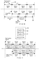
- each frame 32 consists of two interlaced fields 33 and 34 as illustrated in Figure 9 of the accompanying drawings.
- Each field requires a fixed time for digitisation before it can be processed and this is illustrated in Figure 10 of the accompanying drawings.
- the first field is digitised during a period 35 and computing can start at a time 36 such that the first field can be processed in a time period 37, during which the second field can be digitised.
- the time interval from the start of image digitisation to the moment at which the position data are obtained is referred to as the time latency as illustrated at 38.
- the update frequency relates to how frequently the position data are updated. If the computing time does not exceed the time for digitising one field as illustrated in Figure 10, the update frequency is the same as the field digitisation rate.
- the required system response time includes not only the time latency 38 but also the communication time needed to pass the position information to the window steering mechanism and the time required to switch between the current window position and the next window position.
- a ring buffer 39 is a memory buffer containing two memory blocks 40 and 41, each of which acts a field buffer and is large enough to store one field of the digital image.
- the other buffer makes available the previous field for processing.
- the time required to capture a field of an image is 20 milliseconds for a PAL camera operating at 50 fields per second and 16.7 milliseconds for an NTSC camera operating at 60 fields per second.
- the tracking system 2, the display control processor 5 and the steering mechanism 6 shown in Figure 1 have only about 22 milliseconds to detect and respond to head movement for a maximum head speed of 500 millimetres per second and a measuring error of 5 millimetres.
- the time left for processing the image and for covering other latencies due to communication and window steering is about 2 milliseconds. This time is increased to about 5.3 milliseconds if an NTSC camera is used.
- the available time limits the processing techniques which can be used if standard commercially attractive hardware is to be used. If the actual time taken exceeds this time limit, the observer may have to restrict his head movement speed in order to see a flicker-free stereo image.
- the time required for digitising a video field may be reduced if a non-standard high speed camera is used, this is undesirable because of the substantially increased costs. Even if a high speed camera is used, there may be a limit to how fast it can be operated. It is very desirable to avoid the need for special light sources, whether visible or infrared, in order to achieve cost savings and improved ease of use.
- the tracking system 2 should be able to work with ordinary light sources whose intensities may oscillate at 100 or 120 Hz using the normal power supply i.e. twice the power supply frequency of 50 Hz, for instance in the UK, or 60 Hz, for instance in USA. If a camera is operating at a speed close to or above this frequency, images taken at different times may differ significantly in intensity. Overcoming this effect requires extra computing complexity which offsets advantages of using high speed cameras.
- a low resolution camera is preferable so that the volume of image data is as small as possible.
- a video camera would have to cover a field of view at least as large as the viewing region of an autostereoscopic display, so that the head of the observer would occupy only a small portion of the image.
- the resolution of the interesting image regions such as the eyes would therefore be very low.
- the use of field rate halves the resolution in the vertical direction.
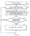
- a known image tracking technique is disclosed by R. Brunelli and T. Poggio "Face Recognition: Features Versus Templates", IEEE Trans on Pattern Analysis and Machine Intelligence, Volume 15 No. 10, October 1993. This technique is illustrated in Figure 12 of the accompanying drawings.
- a "template” which contains a copy of the target image to be located is captured.
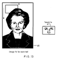
- Figure 13 illustrates an image to be searched at 46 and a template 47 containing the target image. After the template has been captured, it is used to interrogate all subsections of each image field in turn.
- the latest digitised image is acquired and, at step 49, template matching is performed by finding the position at which there is a best correlation between the template and the "underlying" image area.
- a subsection of the image 46 having the same size and shape as the template is selected from the top left corner of the image and is correlated with the template 47.
- the correlation is stored and the process repeated by selecting another subsection one column of pixels to the right. This is repeated for the top row of the image and the process is then repeated by moving down one row of pixels.
- a step 50 determines whether the peak or best correlation value is greater than a predetermined threshold. If so, it may be assumed that the target image has been found in the latest digitised image and this information may be used, for instance as suggested at 51, to control an observer tracking autostereoscopic display. When the next digitised image has been captured, the steps 48 to 51 are repeated, and so on.
- US 3 828 122 discloses a target tracking apparatus for an airborne missile having a video camera for providing a series of images.
- a user defines a target on the first image by moving a large rectangle (containing a small rectangle) over the image on a display.
- the image inside the small rectangle is stored in a target memory.
- the position of the image inside the large rectangle is stored in a current frame memory and the apparatus determines whether the large rectangle is still centred on the target.
- the contents of the target memory are correlated with the contents of the current frame memory for all positions of the small rectangle within the large rectangle and the position giving the highest correlation is selected.
- template matching is relatively easy for computer implementation, it is a computing-intensive operation.
- Direct template matching requires very powerful computer hardware which is impractical for commercial implementation.
- EP 0 579 319 discloses a method of tracking movement of a face in a series of images from a videophone.
- the centroid and motion vector for the face image are determined in a first frame and used to estimate the centroid in a subsequent frame.
- An image is "grown" around the estimated centroid by comparing areas around the centroids in the first and subsequent frames.
- the motion vector is estimated by comparing face positions in the first frame and in a preceding frame.
- the shape and size of the image grown around the centroid may differ from frame to frame.
- the centroid does not therefore refer to the same place in the face image, such as the mid point between the eyes of an observer, and this results in substantial errors in tracking.
- subsequent estimations of the centroid position are based on determining the motion vector. Errors in determining the motion vector may therefore accumulate.
- this technique may be suitable for videophone applications, it is not sufficiently accurate for use in observer tracking autostereoscopic displays.
- an image tracking system comprising first means for presenting a sequence of images and second means for determining the position of a target image in a previously presented image from the first means, characterised by third means for determining movement of the target image between the previously presented image and a subsequently presented image from the first means, and fourth means for indicating the position of the target image in the subsequently presented image as the position determined by the second means modified by the movement determined by the third means.
- an image tracking system which provides a rapid indication of the position of the target image but which does not require undesirably or uncommercially large computing power. Movement of the target image between images can be detected relatively quickly but cannot be used alone because of the accumulation of errors. Determining the position of the target image takes more time but can be performed on the basis of an earlier image for which more time is available. For the or each tracking cycle, the indicated position is based on the accurately determined position by the second means and the movement determined by the third means so that errors do not accumulate and an indication of the position of the target image of good accuracy is provided relatively quickly. Commercially acceptable computing power may be used so that the tracking system is commercially attractive for many applications.
- the previously and subsequently presented images may be any two images from the sequence, it is preferred for the subsequently presented image to be consecutive with the previously presented image.
- the previously presented image may comprise each of the images of the sequence in turn.
- the first means may be arranged to present the sequence of images in real time.
- the subsequently presented image may be the currently presented image.
- the first means may comprise a video camera.
- the first means may comprise a memory for storing the previously presented image and the subsequently presented image.
- the sequence of images may comprise consecutive fields of interlaced fields.
- the second, third and fourth means may comprise a programmed data processor.
- the fourth means is preferably arranged to add the movement determined by the third means to the position determined by the second means.
- the third means may be arranged to determine the movement as soon as the subsequently presented image has been presented by the first means.
- the second means may be arranged to determine the position of the target image in the subsequently presented image as soon as the third means has determined the movement.
- the second means may be arranged to search for the target image in a first image portion which is smaller than the images of the sequence and which includes the position indicated by the fourth means.
- the position indicated by the fourth means may be substantially at the centre of the first image portion.
- the second means may be arranged to search for the target image in the whole of the previously presented image if the search in the image portion is unsuccessful.
- the second means may be arranged to search for the target image in the whole of an initial previously presented image.
- the second means may be arranged to perform template matching of the target image at a plurality of first positions in the first image portion to find a best match.
- the second means may be arranged to perform template matching of the target image at a plurality of second positions which are more finely spaced than the first positions and which are disposed adjacent a position corresponding to the best match.
- the second means may be arranged to perform a correlation between the target image and a respective region corresponding to each of the first and (when present) second portions and to select the highest correlation.
- the second means may be arranged to compare the highest correlation with a threshold for acceptability.
- the system may comprise fifth means for capturing the target image by storing a portion of one of the images of the sequence.
- the fifth means may comprise a display for displaying the sequence of images, an image generator for generating a border image on the display, and a user operable control for actuating capture of an image region within the border image.
- the fifth means may comprise a further user operable control for controlling the position of the border image on the display.
- the third means may be arranged to determine movement at a plurality of image elements in a second image portion which is wholly within and smaller than the target image.
- the third means may be arranged to determine translational movement of the target image.
- x i and y i are Cartesian coordinates of an ith image element
- i is each integer such that 1 ⁇ i ⁇ j and j is an integer greater than one
- f 1 and f 2 are functions representing the previously and subsequently presented images and ⁇ x and ⁇ y are the Cartesian components of the movement.
- an observer tracking autostereoscopic display including a system in accordance with the first aspect of the invention.
- the first means may comprise a video camera whose optical centre is disposed at an optical centre of the display.
- an image tracking method for sequentially presented images comprising determining the position of a target image in a previously presented image, determining movement of the target image between the previously presented image and a subsequently presented image, and indicating the position of the target image in the subsequently presented image as the position in the previously presented image modified by the determined movement.
- the technique can operate under ambient light without any special arrangement of lighting sources. This improves the ease of use for a wider application environment. There is no visual discomfort because no active visible or infrared lighting sources are shone at the eyes. Cost is reduced because components and power supplies for active light sources are not required.
- the tracking system can relocate the target within such a short time that the user does not feel any substantial delay before being able to see the stereoscopic picture again. There is no loss of performance during following tracking processes and there is no need to reinitialise the system unless ambient lighting has changed significantly.
- Figure 16 shows an observer tracking autostereoscopic display constituting an embodiment of the invention and including a video image tracking system also constituting an embodiment of the invention.
- the tracking system 2 shown in Figure 16 differs from that shown in Figure 1 in that the tracking sensor 3 comprises a Sony XC999 NTSC camera operating at a 60 Hz field rate and the tracking processor 4 is provided with a mouse 60 and comprises a Silicon Graphics entry level machine of the Indy series equipped with an R4400 processor operating at 150 MHz and a video digitiser and frame store having a resolution of 640x240 picture elements (pixels) for each field captured by the camera 3.
- the camera 3 is disposed on top of the 3D display 7 and points towards the observer 8 who sits in front of the display.
- the normal distance between the observer 8 and the camera 3 is about 0.85 metres, at which distance the observer has a freedom of movement in the lateral or X direction of about 500 millimetres.
- the distance between two pixels in the image formed by the camera 3 corresponds to about 0.7 and 1.4 millimetres in the X and Y directions, respectively, the Y resolution being halved because each interlaced field is individually used.
- the template described hereinafter is selected to have 150x50 pixels, corresponding to a region of about 105x70 millimetres.
- the mouse 60 is used during template capture as described hereinafter.
- the camera 3 captures and presents to the processor 4 a continuous sequence of images of the user under ambient lighting.
- Figure 17 illustrates in general terms the tracking method performed by the processor 4.
- a template comprising a target image is captured interactively at step 61.
- a tracking stage begins with a global template search at step 62.
- a movement detection step 63 and a local target search 64 are followed by a step 65 checks whether tracking has been lost. If so, control returns to step 62 to perform another global template search. If tracking has not been lost, control returns to the motion detection step 63.
- steps 63 to 65 form a tracking loop which is performed for as long as tracking is maintained.
- the motion detection step 63 supplies position data as indicated at 66 by a differential movement method which determines the movement of the target image between consecutive fields and adds this to the position found by local template matching in the preceding step 64 for the earlier of the fields.
- Figure 18 illustrates the tracking method of Figure 17 in more detail.
- the interactive template capture step 61 makes use of the display 7 and the mouse 60 to allow the user to select the target image which is to form the template.
- the display 7 displays an image of the observer 8 as captured by the video camera 3.
- the processor 4 overlays the image with a graphical guide 67 of the required template size and with text indicating that the observer should place himself so that his eyes are inside the rectangle 67 on the display 7 and aligned with the middle line 68.
- the observer When the observer has correctly positioned himself with respect to the graphical guide 67, he operates a button of the mouse 60 so that the processor 4 captures and stores the part of the image of the observer inside the graphical guide 67 for use as a template or target image.
- the mouse may be used to drag the graphical guide 67 so that it is correctly aligned with the observer's eyes, after which the mouse button is pressed to store the target image.
- An advantage of the interactive template capture 61 is that the observer is able to make the decision on the selection of the template with acceptable alignment accuracy. This involves the recognition of the human face and the selection of the interesting image region, such as the eye region. Whereas human vision renders this process trivial, template capture would be difficult for a computer, given all possible types of people with different age, sex, eye shape and skin colour under various lighting conditions. In fact, template capture can be performed for observers who wear glasses of any shape and colour whereas other known types of tracking systems cannot cope with observers wearing glasses.
- the step 61 comprises a step 69 in which the latest digital image is retrieved from the frame store of the processor 4.
- step 70 the graphics overlay to indicate the template position is drawn.
- step 71 tests whether the template position is correct by detecting whether an input device such as a mouse button has been operated. If not, control returns to the step 69. Once the target image has been captured, control passes to the global template search step 62.
- a step 72 obtains the next available digital image from the frame store and a step 73 applies template matching to the whole image so as to find an initial position (having coordinates X 0 , Y 0 ) of the target image forming the template. As described hereinafter, this is the position which gives best correlation between the template and the underlying image area.
- a step 74 determines whether the best correlation obtained in the step 73 is greater than a preset threshold. If not, control returns to step 72 and the process is repeated for the next available digital image. If the best correlation exceeds the threshold, control passes to the steps 63, 64 and 65 which provide motion detection with target verification.
- step 75 the last processed image f 1 is stored and the next available image f 2 is retrieved for processing.
- Step 76 applies a differential method as described hereinafter to the images f 1 and f 2 to calculate the motion or movement of the template between the images, which motion has Cartesian components ⁇ X and ⁇ Y.
- Step 77 updates the position data by adding the movement calculated in the step 76 to the position determined during the previous template matching step so that the position data X 0 and Y 0 output by a step 78 to the window steering mechanism 6 via the display control processor 5 is formed as X 0 + ⁇ X, Y 0 + ⁇ Y.
- a step 79 applies template matching to the image f 2 as described hereinafter.
- a hierarchical search is applied to a small region of the image centred at the position X 0 , Y 0 .
- the template matching involves a cross-correlation technique and a step 80 detects whether tracking is lost by comparing the best correlation obtained in the step 79 with a preset threshold. If the best correlation is less than the preset threshold, control returns to the step 72 of the global template search 62 so as to relocate the position of the target image within the next available digital image. If the best correlation is greater than the preset threshold, step 81 updates the position data by entering the position of the best correlation as the parameters X 0 and Y 0 . Control then returns to the step 75 and the steps 75 to 81 are repeated for as long as observer tracking is required.
- the template matching step 73 is of the type described hereinbefore with reference to Figures 12 to 14. It is necessary to locate the target image within the whole image area as an initial step and whenever tracking is lost as determined by step 80. In particular, the differential movement detection method 76 cannot begin until the position of the target image within the whole image is known.
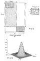
- template matching is performed by cross-correlating the target image in the template with each subsection overlaid by the template as described with reference to Figure 14.
- the similarity between the template and the current subsection of the image may be measured by any suitable metric but the normalised cross-correlation is used in the preferred embodiment.
- the normalised cross-correlation C(x 0 ,y 0 ) for the coordinates x 0 ,y 0 at the top left corner of the image area to be matched with the template is calculated as follows: where
- the values of the cross-correlation C(x 0 ,y 0 ) are in the range of [0.0,1.0], where the maximum value 1.0 is achieved when the template is identical to the underlying image.
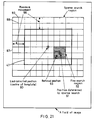
- the same template matching technique is used in the step 79 but, in this case, template matching is applied to a relatively small region within the currently available image as illustrated in Figure 20.
- the target image position located in the previous image field is indicated at 85.
- the maximum movement which can occur is limited by the maximum speed of movement of the observer. In the specific example of hardware described hereinbefore, this corresponds to a maximum vertical or horizontal movement 86 of about 8.33 millimetres. Accordingly, the eye region of the observer must be within a boundary 87 having the same (rectangular) shape as the template and concentric therewith but taller and wider by 16.67 millimetres.
- the template matching step 79 is thus constrained within the boundary 87 so as to minimise the computing time.
- Template matching is performed in first and second sub-steps.
- first sub-step template matching is performed at sparsely displaced positions within the whole image for the step 73 or within the boundary 87 for the step 79.
- image elements such as 88 and 89 at the intersections of a relatively coarse grid of lines are used so that the template and the underlying image region are subsampled to reduce the volume of data which has to be processed in the cross-correlation calculation.
- the data representing each image element may be truncated so as to reduce the calculation time.
- the last detected position of the target image is indicated at 90.
- the first sub-step of the template matching it is, for example, found that the maximum correlation occurs for the target image centred on the position 91.
- the second sub-step is then performed so as to refine the new position of the target image.
- the same cross-correlation calculations are performed but, in this case, the search is confined to a smaller region 92, each of whose dimensions is twice the sparse step in the first sub-step.
- This sub-step is performed with a finer step and higher image element resolution and results in a refined position 93 being found for the target image in the currently processed image field.
- the template matching step may be divided into more than two sub-steps, it has been found that, in practice, a two sub-step arrangement is adequate in terms of efficiency and accuracy. This is because, in the first sub-step, the step size between two neighbouring positions cannot be too large as otherwise it might easily miss the true "coarse" position.
- the steps 74 and 80 compare the best cross-correlation values obtained in the steps 73 and 79, respectively, with a preset threshold to determine whether the target image is present in the current image (in the case of the step 74) or is present within the boundary 87 of the image (for the step 80).
- the cross-correlation value at the best-matched position would be 1 if:
- the best cross-correlation value is therefore compared with the preset threshold to establish whether an acceptable match has been found and to prevent the system from locking onto inappropriate image portions of relatively low cross-correlation value.
- the preset threshold is determined heuristically by experimenting with a large number of people of different types under various lighting conditions. A typical value for the threshold is 0.5 for the case where normalised cross-correlation with a maximum value of 1.0 is used.
- the template 47 may have any shape, a rectangular shape is preferred because it is easier for computer processing.
- the size of the template is important in that it can affect the computing efficiency and accuracy in determining the position of the target image. Larger templates tend to produce a sharper peak correlation so that the peak position can be determined more accurately, mainly because a larger image region contains more features of the face so that a small movement away from the peak position would change the cross-correlation value more substantially. However, a larger template requires more computing time. Also, the template should not exceed the boundary of the face of the observer in the image so as to prevent template matching from being affected by the background content of the images. A typical size for balancing these factors is one which is just large enough to cover the two eye regions of the observer in the images. For the parameters described hereinbefore, a template size of 150 by 50 image picture elements is suitable.
- the differential method 76 measures the relative movement between two consecutive image fields and assumes that this movement has been purely translational.
- the movement is determined from the intensity difference of the two consecutive image fields using the well-known Taylor approximations, for instance as disclosed in T.S. Huang (Editor), Image Sequence Analysis, ISBN 3-540-10919-6, 1983.
- f 1 (x,y) denotes the intensity of an image feature in the first of the consecutive fields at a point (x,y) and the image feature moves by ( ⁇ x, ⁇ y) so that it is at position (x+ ⁇ x,y+ ⁇ y) in the second field
- ⁇ x and ⁇ y are the unknowns representing the movement.
- a pair of pixels from two consecutive images produce one equation so that two pairs of pixels produce a linear system of two equations, which can be solved for the two unknowns to give the amount of movement.
- a larger number of pixels is used to reduce random errors using the well known least squares method. For instance, 50 to 60 pairs of image picture elements may be used.
- the pairs of elements should be selected from the target image, for instance the eye regions of the observer.
- the actual position of the target is not known before the amount of movement between consecutive fields has been determined.
- the curves 95 and 96 shown in Figure 22 represent the images of a one dimensional moving target at times t 1 and t 2 , respectively, corresponding to consecutive fields of an image.
- a point P 1 at a position x 0 at time t 1 becomes a point P 1 ' at a position x 0 + ⁇ x at time t 2 .
- the point P 2 at time t 1 becomes a point P' 2 at time t 2 .
- the movement ⁇ x can be calculated from the intensity difference ⁇ f at the position X 0 and the gradient of the target intensity at this position.
- the parameters ⁇ a,b,c,d,e,g ⁇ are determined by minimising the following cost function: where the summation is over the 3x3 window centred at the current pixel. The minimisation is achieved when the partial derivative with each parameter is zero. This provides a system of equations which can easily be solved.
- the differential method 76 is computationally efficient and, in the specific embodiment as described herein, requires only about 2 milliseconds while providing suitable accuracy so that the output of position data supplied at step 78 may be used to control the steering mechanism 6 of the autostereoscopic display.
- the motion detection method cannot be used on its own to achieve robust tracking because there are always measuring errors in the detected movement. Merely repeating the motion detection method without intervening correction causes errors to accumulate so that accurate tracking is rapidly lost.
- the template matching step 79 is necessary to provide an accurate position measurement for each consecutive field and the errors occurring in the differential method 76 for a single iteration are too small to affect accurate observer tracking.
- the target verification provided by the step 79 verifies that, at the detected position, the target image is indeed there and also refines the position data before the next motion detection step 76.
- the motion detection step takes about 2 milliseconds which, in the case of a field repetition rate of 60 Hz leaves about 14.7 milliseconds before the next digitised image is ready. This "waiting time" is sufficient for the template matching step 79 to perform the target verification.
- the step 77 adds the movement determined in the step 76 to the position determined in the step 79 for the previous image field.
- accumulative errors in the differential method step 76 are avoided since the results of only one differential method step 76 (with only one set of errors) are used to indicate the target image position at the step 78.
- the template matching step 79 calculates a target image position containing errors, such errors do not accumulate because the template is matched each time to the current image of the target. The resulting position data is thus always the true position of the target plus a single measuring error.
- the motion detection and template matching work together in an efficient way.
- the motion detection produces position data quickly so that the time latency is as short as possible.
- the result of motion detection confines the search area for template matching.
- the use of template matching confirms the target position and prevents the accumulation of measuring errors due to motion detection.
- This efficient combination makes it possible to produce a reliable tracking system which is suitable for observer tracking autostereoscopic 3D displays in that it satisfies the requirements of short time latency, high update frequency and sufficient measurement accuracy.
- Figure 23 illustrates the timing of the steps 76 and 79 in relation to the timing of digitisation of the sequence of image fields. Digitisation starts at the time indicated at 97 and, using the NTSC video camera with a 60 Hz field rate as shown in Figure 16, each field is digitised in a period of 16.67 milliseconds.
- the processor 4 contains a ring buffer of the type illustrated in Figure 11 so that each field is available from its respective buffer memory whilst the subsequent field is being captured.
- the step 76 is performed in about 2 milliseconds and the position data Pmd is then available for adding to the position Ptm obtained in the preceding step 79 by template matching.
- the step 76 begins immediately after a fresh field has been captured and digitised.
- the step 79 ends immediately after the step 76 has been completed and takes about 10 milliseconds.
- the whole image tracking for each image field is completed within the time required to digitise an image field so that the repetition rate of the observer position measurements is equal to the field repetition rate of 60 Hz.
- the latency of position measurements is 18.7 milliseconds and an X accuracy of better than 5 millimetres can be obtained. This is sufficient for the image tracking system to be used, for instance, in the autostereoscopic display illustrated in Figure 2.
- the global template search 62 takes a fixed time of approximately 60 milliseconds. If the target image is lost during the steps 63, 64 and 65, for instance if the observer moves out of the field of view of the video camera 3, the tracking system detects that the target image has been lost and changes to the global template search 62 until the observer moves back into the field of view and is located again by the tracking system.
- the differential method 76 works well when the motion between two consecutive fields does not exceed three to four image picture elements. This is about the average speed of an observer for a typical embodiment of the autostereoscopic display shown in Figure 2 but, in practice, the observer may move twice as fast as this from time to time. In these circumstances, the differential method tends to underestimate the amount of movement.
- One technique for solving this problem is to use an iterative differential method. For instance, if the target image has moved by 7 pixels between consecutive fields but the first iteration estimates a movement of 4 pixels, the second image field can be shifted by 4 pixels before another iteration. The relative movement between the shifted field and the previous field is now about 3 pixels which may be accurately measured. Although more than two iterations may be used, two iterations have been found to be adequate in practice.
- the observer position data may be represented in terms of Cartesian coordinates as illustrated in Figure 3.
- the tracking system described hereinbefore implements XY head tracking, but X position data alone may be sufficient for steering the viewing windows if the observer does not move in the Z direction but remains in the window plane 23 of the display.
- Z tracking is required if the observer is to move in the Z direction.
- the optical centre of a lens 99 of the camera 3 is aligned with the optical centre 29 of the display, Z tracking is not explicitly required.
- the viewing zones 28 are angularly spaced in the horizontal XZ plane.
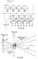
- the optical centre of the camera lens 99 aligned with the optical centre 29 of the display as shown in Figure 24, all points on the same switching line such as 100 are imaged to the same point such as 101 on the image plane 102 of the camera 3.
- the X position of the camera pixel image therefore indicates the angular position of the observer and can be supplied directly to the optical system of the display 7 to provide correctly steered viewing windows without requiring any knowledge of the Z position of the observer.
- This particular arrangement therefore allows the use of a single camera with increased accuracy and shortened response time so that the tracking system is particularly suitable for this type of autostereoscopic display.
- autostereoscopic displays typically allow some longitudinal viewing freedom for the observer.
- the observer will perceive a 3D image across the whole of the display.
- movement in the longitudinal or Z direction causes a change of the size of the target image as the observer moves towards and away from the video camera 3.
- the differential method 76 uses the latest two consecutive image fields so that the target may only move a small distance. The scaling effect is therefore minimal and does not cause a serious problem.
- the scaling effect is more important to the template matching steps 73 and 79 because each image field is always searched with a fixed template acquired during the template capture step 61.
- the result of the scaling effect is that the maximum correlation is lower than the optimum value of 1.
- the tracking system can tolerate longitudinal movement of about 150 millimetres forwards or backwards from the best viewing position of 0.85 metres with a measuring error not exceeding 5 millimetres.
- a preset threshold is used in the steps 74 and 80 to test whether the target image has been located.
- the preset threshold has to be sufficiently small so that it can accommodate different people at different positions and orientations under various lighting conditions. However, the threshold should be sufficiently large so that it can discriminate a true target image from a false one.
- Target verification may be enhanced by further checking using additional methods such as hue (H) saturation (S) value (V) measurement as illustrated in Figures 25 and 26.
- the image tracking method shown in Figure 25 differs from that shown in Figures 17 and 18 in that steps 103 and 104 are inserted. It is well known that human skin tends to be of uniform saturation. This uniformity is less affected by different lighting conditions than other image features, such as grey levels. With uniform illumination, both hue and saturation of the face change smoothly over a large portion of the face. Even with non-uniform illumination, the saturation of the image remains fairly balanced on both sides of the observer face whereas the intensity picture could be visibly dark on one side and bright on the other. Also, the average saturation value over the observer face region differs from that of the background more significantly. The mean value of the saturation over the observer face changes very little during head movement. This therefore provides an additional check for target verification.
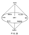
- Figure 26 illustrates HSV as a double cone containing all possible colours of light.
- the axis of the double cone represents a grey scale progression from black to white.
- Distance from the axis represents saturation.
- Angular direction around the axis represents hue.
- conversion to HSV format may be obtained by finding the maximum and minimum values of the RGB signals.
- the V component is then given by the value of the maximum signal.
- the saturation S is defined as zero when the V component is zero and otherwise as the difference between the maximum and minimum RGB values divided by the maximum value.
- the hue is computed as follows: where d is the difference between the maximum and minimum RGB values and cmax is the maximum of the RGB values.
- the step 103 converts the region of the image field underlying the template at the optimum position from RGB to HSV format as described hereinbefore.
- the mean value sl of the target image is calculated and compared with the mean saturation of the template (which is fixed and which may be calculated during the template capture step 61).
- the difference S in mean saturation is calculated as
- the system described hereinbefore employs a single template for a single user whose face is assumed to be in a roughly upright position during any head movement.
- the user is allowed to tilt and/or rotate his head within a small amount.
- the exact range is different from user to user, depending on a number of factors such as the face size, the facial features and signal-to-noise ratio in the image.
- the system may be modified to allow a larger degree of rotation and tilting by using multiple templates.
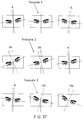
- the first row of Figure 27 illustrates the use of a single template which would allow the user to tilt from an angle of -A degrees to +A degrees. If a second template is obtained at an angle of 2A, this template may be used to match eye regions that are tilted in the range of A to 3A degrees. Similarly a third template may be obtained at an angle of -2A and extend the tilting range from -A to -3A degrees.
- the first template may be used initially to find the best-matched region. If the best correlation value is above the pre-set threshold, then the eye region is found; otherwise the second template is used to apply the template matching process. If the best correlation value is above the pre-set threshold, then the eye region is found; otherwise the third template is used to apply the template matching process.
- the template matching for the next frame may start with the second template rather than the first template. If the best correlation value is above the pre-set threshold, then the eye region is found; otherwise the other two templates may be used in turn until the eye region is found.
- the allowed tilting range may be further extended.
- the second and third templates may be obtained using the interactive method as described hereinbefore with the user keeping his head tilted to the desired degree. However, this may not be convenient and may not be necessary, as the second and third templates may be obtained computationally by rotating the first template by the desired degree.
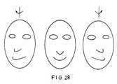
- This method may be applied to extend the range of rotation allowed for a user who rotates his head about a vertical axis, as illustrated in Figure 28.
- the extra templates however have to be captured manually and individually.
- tracking system in the described embodiment is embodied as a programmed data processor
- other implementations include the use of discrete components, for instance comprising a camera, a digital signal processing chip and a suitable store.
- the system may also be implemented as a special purpose silicon chip or chip set which may at least in part be built into a camera system.
- Such a camera may have a first output for a standard video signal and a second output for position data.
- a system integrated directly with the camera sensor such as a CMOS based camera system would not require digital/analogue and analogue/digital converters to generate and process analogue video data, thus providing an opportunity of reducing cost and improving performance.
- CMOS complementary metal-senor
Landscapes
- Engineering & Computer Science (AREA)
- Multimedia (AREA)
- Signal Processing (AREA)
- Physics & Mathematics (AREA)
- General Physics & Mathematics (AREA)
- Optics & Photonics (AREA)
- Testing, Inspecting, Measuring Of Stereoscopic Televisions And Televisions (AREA)
- Image Analysis (AREA)
- Position Input By Displaying (AREA)
- Controls And Circuits For Display Device (AREA)
Applications Claiming Priority (2)
| Application Number | Priority Date | Filing Date | Title |
|---|---|---|---|
| GB9707782A GB2324428A (en) | 1997-04-17 | 1997-04-17 | Image tracking; observer tracking stereoscopic display |
| GB9707782 | 1997-04-17 |
Publications (2)
| Publication Number | Publication Date |
|---|---|
| EP0877274A2 true EP0877274A2 (de) | 1998-11-11 |
| EP0877274A3 EP0877274A3 (de) | 1999-12-29 |
Family
ID=10810934
Family Applications (1)
| Application Number | Title | Priority Date | Filing Date |
|---|---|---|---|
| EP98302989A Withdrawn EP0877274A3 (de) | 1997-04-17 | 1998-04-17 | Bildverfolgungssystem und Verfahren und autostereoskopische Anzeigevorrichtung mit Beobachter-Nachführung |
Country Status (4)
| Country | Link |
|---|---|
| US (1) | US6075557A (de) |
| EP (1) | EP0877274A3 (de) |
| JP (1) | JP3565707B2 (de) |
| GB (1) | GB2324428A (de) |
Cited By (10)
| Publication number | Priority date | Publication date | Assignee | Title |
|---|---|---|---|---|
| EP1542153A1 (de) * | 2003-12-11 | 2005-06-15 | Sony United Kingdom Limited | Objekterkennung |
| EP1621153A1 (de) * | 2004-07-28 | 2006-02-01 | BrainLAB AG | Stereoskopische Visualisierungsvorrichtung für Patientenbilddaten und Videobilder |
| EP1298933A3 (de) * | 2001-09-26 | 2006-10-04 | Lg Electronics Inc. | Videofernmeldesystem |
| US7203277B2 (en) | 2003-04-25 | 2007-04-10 | Brainlab Ag | Visualization device and method for combined patient and object image data |
| US7359105B2 (en) | 2006-02-07 | 2008-04-15 | Sharp Kabushiki Kaisha | Spatial light modulator and a display device |
| US7463823B2 (en) | 2003-07-24 | 2008-12-09 | Brainlab Ag | Stereoscopic visualization device for patient image data and video images |
| CN100527166C (zh) * | 2003-09-02 | 2009-08-12 | 松下电器产业株式会社 | 目标行进方向检测方法 |
| US8401081B2 (en) | 2006-08-11 | 2013-03-19 | Thomson Licensing | Accurate motion portrayal for display and digital projectors |
| CN104272733A (zh) * | 2012-02-16 | 2015-01-07 | 迪蒙科有限公司 | 自动立体显示设备及驱动方法 |
| CN113524197A (zh) * | 2021-08-10 | 2021-10-22 | 深圳市金凯博自动化测试有限公司 | 一种高效快速自动精准定位装置 |
Families Citing this family (144)
| Publication number | Priority date | Publication date | Assignee | Title |
|---|---|---|---|---|
| JP3802653B2 (ja) * | 1997-05-21 | 2006-07-26 | オリンパス株式会社 | 立体画像表示装置 |
| AUPP048097A0 (en) * | 1997-11-21 | 1997-12-18 | Xenotech Research Pty Ltd | Eye tracking apparatus |
| US6239830B1 (en) * | 1998-01-21 | 2001-05-29 | New York University | Displayer and method for displaying |
| CN1178467C (zh) * | 1998-04-16 | 2004-12-01 | 三星电子株式会社 | 自动跟踪运动目标的方法和装置 |
| US20010008561A1 (en) * | 1999-08-10 | 2001-07-19 | Paul George V. | Real-time object tracking system |
| US7036094B1 (en) | 1998-08-10 | 2006-04-25 | Cybernet Systems Corporation | Behavior recognition system |
| US7121946B2 (en) * | 1998-08-10 | 2006-10-17 | Cybernet Systems Corporation | Real-time head tracking system for computer games and other applications |
| US6937696B1 (en) | 1998-10-23 | 2005-08-30 | Varian Medical Systems Technologies, Inc. | Method and system for predictive physiological gating |
| US7158610B2 (en) * | 2003-09-05 | 2007-01-02 | Varian Medical Systems Technologies, Inc. | Systems and methods for processing x-ray images |
| US6757422B1 (en) * | 1998-11-12 | 2004-06-29 | Canon Kabushiki Kaisha | Viewpoint position detection apparatus and method, and stereoscopic image display system |
| US6243494B1 (en) * | 1998-12-18 | 2001-06-05 | University Of Washington | Template matching in 3 dimensions using correlative auto-predictive search |
| US6301387B1 (en) * | 1998-12-18 | 2001-10-09 | University Of Washington | Template matching using correlative auto-predictive search |
| US6687386B1 (en) * | 1999-06-15 | 2004-02-03 | Hitachi Denshi Kabushiki Kaisha | Object tracking method and object tracking apparatus |
| US7050606B2 (en) * | 1999-08-10 | 2006-05-23 | Cybernet Systems Corporation | Tracking and gesture recognition system particularly suited to vehicular control applications |
| SG91841A1 (en) * | 1999-11-03 | 2002-10-15 | Kent Ridge Digital Labs | Face direction estimation using a single gray-level image |
| JP2001209802A (ja) * | 1999-11-15 | 2001-08-03 | Fuji Photo Film Co Ltd | 顔抽出方法および装置並びに記録媒体 |
| US20040189804A1 (en) * | 2000-02-16 | 2004-09-30 | Borden George R. | Method of selecting targets and generating feedback in object tracking systems |
| JP3825222B2 (ja) * | 2000-03-24 | 2006-09-27 | 松下電器産業株式会社 | 本人認証装置および本人認証システムならびに電子決済システム |
| KR100710347B1 (ko) * | 2000-05-12 | 2007-04-23 | 엘지전자 주식회사 | 3차원 영상 디스플레이 장치 및 방법 |
| US7221780B1 (en) * | 2000-06-02 | 2007-05-22 | Sony Corporation | System and method for human face detection in color graphics images |
| US20080024598A1 (en) * | 2000-07-21 | 2008-01-31 | New York University | Autostereoscopic display |
| JP3561463B2 (ja) | 2000-08-11 | 2004-09-02 | コナミ株式会社 | 3dビデオゲームにおける擬似カメラ視点移動制御方法及び3dビデオゲーム装置 |
| US6751345B2 (en) * | 2001-02-12 | 2004-06-15 | Koninklijke Philips Electronics N.V. | Method and apparatus for improving object boundaries extracted from stereoscopic images |
| JP2002259991A (ja) * | 2001-02-28 | 2002-09-13 | Sony Corp | 画像処理装置およびその方法 |
| US6760465B2 (en) | 2001-03-30 | 2004-07-06 | Intel Corporation | Mechanism for tracking colored objects in a video sequence |
| US6985179B2 (en) * | 2001-03-30 | 2006-01-10 | Intel Corporaiton | Determining image quality for improving object trackability |
| US6752498B2 (en) | 2001-05-14 | 2004-06-22 | Eastman Kodak Company | Adaptive autostereoscopic display system |
| US20040164939A1 (en) * | 2001-05-15 | 2004-08-26 | Johnson Mark Thomas | Display device comprising a plurality of leds |
| US7769430B2 (en) * | 2001-06-26 | 2010-08-03 | Varian Medical Systems, Inc. | Patient visual instruction techniques for synchronizing breathing with a medical procedure |
| AUPR676201A0 (en) * | 2001-08-01 | 2001-08-23 | Canon Kabushiki Kaisha | Video feature tracking with loss-of-track detection |
| US20030128175A1 (en) * | 2002-01-09 | 2003-07-10 | International Business Machines Corporation | Stereoscopic display system and method |
| US20030210378A1 (en) * | 2002-01-17 | 2003-11-13 | Riza Nabeel Agha | Optoelectronic eye examination system |
| AU2003245283A1 (en) * | 2002-05-15 | 2003-12-02 | The Board Of Governors For Higher Education, State Of Rhode Island And Providence Plantations | An imaging system and method for tracking the motion of an object |
| US7620444B2 (en) | 2002-10-05 | 2009-11-17 | General Electric Company | Systems and methods for improving usability of images for medical applications |
| US7400344B2 (en) * | 2002-12-19 | 2008-07-15 | Hitachi Kokusai Electric Inc. | Object tracking method and object tracking apparatus |
| US20050134685A1 (en) * | 2003-12-22 | 2005-06-23 | Objectvideo, Inc. | Master-slave automated video-based surveillance system |
| AU2003901528A0 (en) * | 2003-03-31 | 2003-05-01 | Seeing Machines Pty Ltd | Eye tracking system and method |
| US7956889B2 (en) | 2003-06-04 | 2011-06-07 | Model Software Corporation | Video surveillance system |
| US8571639B2 (en) * | 2003-09-05 | 2013-10-29 | Varian Medical Systems, Inc. | Systems and methods for gating medical procedures |
| US20050053267A1 (en) * | 2003-09-05 | 2005-03-10 | Varian Medical Systems Technologies, Inc. | Systems and methods for tracking moving targets and monitoring object positions |
| JP4543644B2 (ja) * | 2003-09-16 | 2010-09-15 | 富士ゼロックス株式会社 | データ認識装置 |
| TWI225622B (en) * | 2003-10-24 | 2004-12-21 | Sunplus Technology Co Ltd | Method for detecting the sub-pixel motion for optic navigation device |
| US20050104958A1 (en) * | 2003-11-13 | 2005-05-19 | Geoffrey Egnal | Active camera video-based surveillance systems and methods |
| US20060007191A1 (en) * | 2004-06-03 | 2006-01-12 | International Business Machines Corporation | System and method for adjusting a screen |
| US8300043B2 (en) * | 2004-06-24 | 2012-10-30 | Sony Ericsson Mobile Communications AG | Proximity assisted 3D rendering |
| DE102004059729B3 (de) * | 2004-12-11 | 2006-04-13 | Fraunhofer-Gesellschaft zur Förderung der angewandten Forschung e.V. | Verfahren zur autostereoskopischen Erzeugung von dreidimensionalen Bildinformationen aus gerasterten Subpixelauszügen und Anordnung zur Verfahrensdurchführung |
| RU2322771C2 (ru) | 2005-04-25 | 2008-04-20 | Святослав Иванович АРСЕНИЧ | Стереопроекционная система |
| US7672540B2 (en) * | 2005-07-13 | 2010-03-02 | Siemens Medical Solutions USA, Inc, | Nonrigid registration of cardiac perfusion MR images using adaptive local template matching |
| US9363487B2 (en) * | 2005-09-08 | 2016-06-07 | Avigilon Fortress Corporation | Scanning camera-based video surveillance system |
| US20070058717A1 (en) * | 2005-09-09 | 2007-03-15 | Objectvideo, Inc. | Enhanced processing for scanning video |
| US8098885B2 (en) * | 2005-11-02 | 2012-01-17 | Microsoft Corporation | Robust online face tracking |
| KR100704634B1 (ko) * | 2005-12-19 | 2007-04-09 | 삼성전자주식회사 | 사용자의 위치에 따른 입체 영상을 디스플레이하는 장치 및방법 |
| US20070196005A1 (en) * | 2006-02-23 | 2007-08-23 | White Christopher A | Feature Tracing Process for M-mode Images |
| US20070208904A1 (en) * | 2006-03-03 | 2007-09-06 | Wu-Han Hsieh | Wear leveling method and apparatus for nonvolatile memory |
| US7876906B2 (en) | 2006-05-30 | 2011-01-25 | Sonitus Medical, Inc. | Methods and apparatus for processing audio signals |
| US8291912B2 (en) * | 2006-08-22 | 2012-10-23 | Sonitus Medical, Inc. | Systems for manufacturing oral-based hearing aid appliances |
| EP2064916B1 (de) * | 2006-09-08 | 2018-12-05 | SoundMed, LLC | Verfahren und vorrichtung zur tinnitus-behandlung |
| US8270638B2 (en) | 2007-05-29 | 2012-09-18 | Sonitus Medical, Inc. | Systems and methods to provide communication, positioning and monitoring of user status |
| US20080304677A1 (en) * | 2007-06-08 | 2008-12-11 | Sonitus Medical Inc. | System and method for noise cancellation with motion tracking capability |
| US20090028352A1 (en) * | 2007-07-24 | 2009-01-29 | Petroff Michael L | Signal process for the derivation of improved dtm dynamic tinnitus mitigation sound |
| US20120235632A9 (en) * | 2007-08-20 | 2012-09-20 | Sonitus Medical, Inc. | Intra-oral charging systems and methods |
| US8433080B2 (en) * | 2007-08-22 | 2013-04-30 | Sonitus Medical, Inc. | Bone conduction hearing device with open-ear microphone |
| US8224013B2 (en) | 2007-08-27 | 2012-07-17 | Sonitus Medical, Inc. | Headset systems and methods |
| US7682303B2 (en) | 2007-10-02 | 2010-03-23 | Sonitus Medical, Inc. | Methods and apparatus for transmitting vibrations |
| US20090105523A1 (en) * | 2007-10-18 | 2009-04-23 | Sonitus Medical, Inc. | Systems and methods for compliance monitoring |
| JP4882956B2 (ja) * | 2007-10-22 | 2012-02-22 | ソニー株式会社 | 画像処理装置および画像処理方法 |
| US8795172B2 (en) * | 2007-12-07 | 2014-08-05 | Sonitus Medical, Inc. | Systems and methods to provide two-way communications |
| US8270637B2 (en) | 2008-02-15 | 2012-09-18 | Sonitus Medical, Inc. | Headset systems and methods |
| US7974845B2 (en) | 2008-02-15 | 2011-07-05 | Sonitus Medical, Inc. | Stuttering treatment methods and apparatus |
| US8023676B2 (en) | 2008-03-03 | 2011-09-20 | Sonitus Medical, Inc. | Systems and methods to provide communication and monitoring of user status |
| US8150075B2 (en) | 2008-03-04 | 2012-04-03 | Sonitus Medical, Inc. | Dental bone conduction hearing appliance |
| US20090226020A1 (en) | 2008-03-04 | 2009-09-10 | Sonitus Medical, Inc. | Dental bone conduction hearing appliance |
| US20090270673A1 (en) * | 2008-04-25 | 2009-10-29 | Sonitus Medical, Inc. | Methods and systems for tinnitus treatment |
| US10667727B2 (en) * | 2008-09-05 | 2020-06-02 | Varian Medical Systems, Inc. | Systems and methods for determining a state of a patient |
| US20100061596A1 (en) * | 2008-09-05 | 2010-03-11 | Varian Medical Systems Technologies, Inc. | Video-Based Breathing Monitoring Without Fiducial Tracking |
| US8328360B2 (en) * | 2009-04-03 | 2012-12-11 | Seiko Epson Corporation | Retro-reflective light diffusing autostereoscopic 3D display systems |
| US7993016B2 (en) * | 2009-04-03 | 2011-08-09 | Seiko Epson Corporation | Retro-reflective light diffusing display systems |
| US8287127B2 (en) * | 2009-04-03 | 2012-10-16 | Seiko Epson Corporation | Aerial three-dimensional image display systems |
| US8433082B2 (en) | 2009-10-02 | 2013-04-30 | Sonitus Medical, Inc. | Intraoral appliance for sound transmission via bone conduction |
| US20110181587A1 (en) * | 2010-01-22 | 2011-07-28 | Sony Corporation | Image display device having imaging device |
| JP5398612B2 (ja) * | 2010-03-23 | 2014-01-29 | 富士フイルム株式会社 | 動体検出装置および方法 |
| US20110310003A1 (en) * | 2010-05-21 | 2011-12-22 | Fraunhofer-Gesellschaft Zur Forderung Der Angewandten Forschung E.V. | Image display device and method of displaying images |
| US8651726B2 (en) | 2010-11-19 | 2014-02-18 | Reald Inc. | Efficient polarized directional backlight |
| US20140041205A1 (en) | 2010-11-19 | 2014-02-13 | Reald Inc. | Method of manufacturing directional backlight apparatus and directional structured optical film |
| US9519153B2 (en) | 2010-11-19 | 2016-12-13 | Reald Inc. | Directional flat illuminators |
| US9250448B2 (en) | 2010-11-19 | 2016-02-02 | Reald Inc. | Segmented directional backlight and related methods of backlight illumination |
| US9237337B2 (en) | 2011-08-24 | 2016-01-12 | Reald Inc. | Autostereoscopic display with a passive cycloidal diffractive waveplate |
| KR101887058B1 (ko) * | 2011-11-11 | 2018-08-09 | 엘지전자 주식회사 | 입체영상 처리 장치 및 입체영상 처리 장치의 전력 제어 방법 |
| KR101874494B1 (ko) * | 2011-11-25 | 2018-07-06 | 삼성전자주식회사 | 특징점의 삼차원 위치 계산 장치 및 방법 |
| US8704904B2 (en) | 2011-12-23 | 2014-04-22 | H4 Engineering, Inc. | Portable system for high quality video recording |
| WO2013131036A1 (en) | 2012-03-01 | 2013-09-06 | H4 Engineering, Inc. | Apparatus and method for automatic video recording |
| US9723192B1 (en) | 2012-03-02 | 2017-08-01 | H4 Engineering, Inc. | Application dependent video recording device architecture |
| JP2015513858A (ja) | 2012-03-02 | 2015-05-14 | エイチ4 エンジニアリング, インコーポレイテッドH4 Engineering, Inc. | 多機能自動ビデオ記録装置 |
| CN104380185B (zh) | 2012-05-18 | 2017-07-28 | 瑞尔D斯帕克有限责任公司 | 定向背光源 |
| CN108089340B (zh) * | 2012-05-18 | 2021-08-10 | 瑞尔D斯帕克有限责任公司 | 定向显示设备 |
| US9235057B2 (en) | 2012-05-18 | 2016-01-12 | Reald Inc. | Polarization recovery in a directional display device |
| US9350980B2 (en) | 2012-05-18 | 2016-05-24 | Reald Inc. | Crosstalk suppression in a directional backlight |
| US9678267B2 (en) | 2012-05-18 | 2017-06-13 | Reald Spark, Llc | Wide angle imaging directional backlights |
| EP2850471B1 (de) | 2012-05-18 | 2020-08-26 | RealD Spark, LLC | Gerichtet beleuchtete wellenleiteranordnung |
| US9188731B2 (en) | 2012-05-18 | 2015-11-17 | Reald Inc. | Directional backlight |
| TWI636283B (zh) | 2012-05-18 | 2018-09-21 | 美商瑞爾D斯帕克有限責任公司 | 定向背光源、定向顯示裝置及其光源陣列的控制方法 |
| KR20140011574A (ko) | 2012-07-17 | 2014-01-29 | 삼성디스플레이 주식회사 | 표시 장치 및 그 구동 방법 |
| CN104685867B (zh) | 2012-07-23 | 2017-03-08 | 瑞尔D斯帕克有限责任公司 | 观察者跟踪自动立体显示器 |
| US20140028812A1 (en) * | 2012-07-27 | 2014-01-30 | Kabushiki Kaisha Toshiba | Three-dimensional video display apparatus |
| EP2904778B1 (de) * | 2012-10-02 | 2020-05-27 | RealD Spark, LLC | Zeitlich multiplexierte anzeige mit landschafts- und portraitbetriebsmodi |
| CN105008983B (zh) | 2012-12-21 | 2018-08-07 | 瑞尔D斯帕克有限责任公司 | 用于定向显示器的超透镜组件 |
| KR101996655B1 (ko) * | 2012-12-26 | 2019-07-05 | 엘지디스플레이 주식회사 | 홀로그램 표시 장치 |
| BR112015020160B1 (pt) | 2013-02-22 | 2022-01-18 | Reald Spark, Llc | Retroiluminação direcional |
| JP2014241473A (ja) * | 2013-06-11 | 2014-12-25 | 株式会社東芝 | 画像処理装置、方法、及びプログラム、並びに、立体画像表示装置 |
| EP3011734A4 (de) | 2013-06-17 | 2017-02-22 | RealD Inc. | Steuerung von lichtquellen einer gerichteten rückbeleuchtung |
| TWI510101B (zh) * | 2013-09-12 | 2015-11-21 | Au Optronics Corp | 飽和度調整方法與色彩調整系統 |
| EP3058562A4 (de) | 2013-10-14 | 2017-07-26 | RealD Spark, LLC | Steuerung einer gerichteten anzeige |
| WO2015057588A1 (en) | 2013-10-14 | 2015-04-23 | Reald Inc. | Light input for directional backlight |
| US9551825B2 (en) | 2013-11-15 | 2017-01-24 | Reald Spark, Llc | Directional backlights with light emitting element packages |
| US11067736B2 (en) | 2014-06-26 | 2021-07-20 | Reald Spark, Llc | Directional privacy display |
| US9835792B2 (en) | 2014-10-08 | 2017-12-05 | Reald Spark, Llc | Directional backlight |
| WO2016105541A1 (en) | 2014-12-24 | 2016-06-30 | Reald Inc. | Adjustment of perceived roundness in stereoscopic image of a head |
| RU2596062C1 (ru) | 2015-03-20 | 2016-08-27 | Автономная Некоммерческая Образовательная Организация Высшего Профессионального Образования "Сколковский Институт Науки И Технологий" | Способ коррекции изображения глаз с использованием машинного обучения и способ машинного обучения |
| WO2016168305A1 (en) | 2015-04-13 | 2016-10-20 | Reald Inc. | Wide angle imaging directional backlights |
| US10228505B2 (en) | 2015-05-27 | 2019-03-12 | Reald Spark, Llc | Wide angle imaging directional backlights |
| KR102463169B1 (ko) | 2015-09-07 | 2022-11-04 | 삼성전자주식회사 | 시점 추적 방법 및 장치 |
| CN108351951B (zh) | 2015-10-26 | 2023-02-07 | 瑞尔D斯帕克有限责任公司 | 智能隐私系统、设备及其方法 |
| US10459321B2 (en) | 2015-11-10 | 2019-10-29 | Reald Inc. | Distortion matching polarization conversion systems and methods thereof |
| WO2017083041A1 (en) | 2015-11-13 | 2017-05-18 | Reald Inc. | Wide angle imaging directional backlights |
| US10359561B2 (en) | 2015-11-13 | 2019-07-23 | Reald Spark, Llc | Waveguide comprising surface relief feature and directional backlight, directional display device, and directional display apparatus comprising said waveguide |
| CN108463787B (zh) | 2016-01-05 | 2021-11-30 | 瑞尔D斯帕克有限责任公司 | 多视角图像的注视校正 |
| US11079619B2 (en) | 2016-05-19 | 2021-08-03 | Reald Spark, Llc | Wide angle imaging directional backlights |
| EP4124795B1 (de) | 2016-05-23 | 2024-04-10 | RealD Spark, LLC | Direktionale hintergrundleuchten zur weitwinkelbildgebung |
| JP6390671B2 (ja) * | 2016-07-29 | 2018-09-19 | オムロン株式会社 | 画像処理装置および画像処理方法 |
| WO2018129059A1 (en) | 2017-01-04 | 2018-07-12 | Reald Spark, Llc | Optical stack for imaging directional backlights |
| WO2018187154A1 (en) | 2017-04-03 | 2018-10-11 | Reald Spark, Llc | Segmented imaging directional backlights |
| US10303030B2 (en) | 2017-05-08 | 2019-05-28 | Reald Spark, Llc | Reflective optical stack for privacy display |
| US10126575B1 (en) | 2017-05-08 | 2018-11-13 | Reald Spark, Llc | Optical stack for privacy display |
| EP3622342A4 (de) | 2017-05-08 | 2021-02-17 | RealD Spark, LLC | Optischer stapel für direktionale anzeige |
| RU2698919C2 (ru) * | 2017-07-18 | 2019-09-02 | Святослав Иванович АРСЕНИЧ | Стереодисплей (варианты), видеокамера для стереосъёмки и способ компьютерного формирования стереоизображений для этого стереодисплея |
| EP4293574A3 (de) | 2017-08-08 | 2024-04-03 | RealD Spark, LLC | Einstellung einer digitalen darstellung eines kopfbereiches |
| TWI878209B (zh) | 2017-09-15 | 2025-04-01 | 美商瑞爾D斯帕克有限責任公司 | 顯示裝置及應用於顯示裝置的視角控制光學元件 |
| US11070791B2 (en) | 2017-11-06 | 2021-07-20 | Reald Spark, Llc | Privacy display apparatus |
| EP3743766B1 (de) | 2018-01-25 | 2026-02-11 | RealD Spark, LLC | Berührungsbildschirm für privatsphärenanzeige |
| CN115718382A (zh) | 2018-01-25 | 2023-02-28 | 瑞尔D斯帕克有限责任公司 | 用于防窥显示装置的反射式光学堆叠物 |
| EP4214441A4 (de) | 2020-09-16 | 2024-08-28 | RealD Spark, LLC | Fahrzeugaussenbeleuchtungsvorrichtung |
| US12585094B2 (en) | 2022-06-22 | 2026-03-24 | Reald Spark, Llc | Anamorphic directional illumination device |
| WO2024030274A1 (en) | 2022-08-02 | 2024-02-08 | Reald Spark, Llc | Pupil tracking near-eye display |
| CN119948379A (zh) | 2022-08-11 | 2025-05-06 | 瑞尔D斯帕克有限责任公司 | 变形定向照明装置 |
Family Cites Families (15)
| Publication number | Priority date | Publication date | Assignee | Title |
|---|---|---|---|---|
| US3828122A (en) * | 1970-09-29 | 1974-08-06 | Bendix Corp | Tv area correlation tracker |
| GB1605201A (en) * | 1978-03-02 | 1983-05-25 | Elliott Brothers London Ltd | Target tracking arrangements |
| US4975960A (en) * | 1985-06-03 | 1990-12-04 | Petajan Eric D | Electronic facial tracking and detection system and method and apparatus for automated speech recognition |
| US5016282A (en) * | 1988-07-14 | 1991-05-14 | Atr Communication Systems Research Laboratories | Eye tracking image pickup apparatus for separating noise from feature portions |
| US5323470A (en) * | 1992-05-08 | 1994-06-21 | Atsushi Kara | Method and apparatus for automatically tracking an object |
| GB9215102D0 (en) * | 1992-07-16 | 1992-08-26 | Philips Electronics Uk Ltd | Tracking moving objects |
| US5349379A (en) * | 1992-09-09 | 1994-09-20 | Dimension Technologies Inc. | Autostereoscopic display illumination system allowing viewing zones to follow the observer's head |
| EP0602934B1 (de) * | 1992-12-17 | 1999-03-10 | Sharp Kabushiki Kaisha | Autostereoskopisches Wiedergabegerät |
| DE69422803T2 (de) * | 1993-03-03 | 2000-06-15 | Graham Stewart B. Street | Bildausrichtung und Gerät |
| EP1209508B1 (de) * | 1993-12-01 | 2004-10-27 | Sharp Kabushiki Kaisha | Display für dreidimensionale Bilder |
| AUPN003894A0 (en) * | 1994-12-13 | 1995-01-12 | Xenotech Research Pty Ltd | Head tracking system for stereoscopic display apparatus |
| DE19500315C1 (de) * | 1995-01-07 | 1995-10-26 | Siegbert Prof Dr Ing Hentschke | Personenadaptiver autostereoskoper Shutter-Bildschirm (PAAS) |
| GB2297876A (en) * | 1995-02-09 | 1996-08-14 | Sharp Kk | Observer tracking autostereoscopic display |
| GB2306826A (en) * | 1995-10-18 | 1997-05-07 | Sharp Kk | Display, method of calibrating an observer tracking display and observer tracking autostereoscopic 3D display |
| GB2317291A (en) * | 1996-09-12 | 1998-03-18 | Sharp Kk | Observer tracking directional display |
-
1997
- 1997-04-17 GB GB9707782A patent/GB2324428A/en not_active Withdrawn
-
1998
- 1998-04-16 JP JP10622298A patent/JP3565707B2/ja not_active Expired - Fee Related
- 1998-04-16 US US09/061,690 patent/US6075557A/en not_active Expired - Fee Related
- 1998-04-17 EP EP98302989A patent/EP0877274A3/de not_active Withdrawn
Cited By (13)
| Publication number | Priority date | Publication date | Assignee | Title |
|---|---|---|---|---|
| EP1298933A3 (de) * | 2001-09-26 | 2006-10-04 | Lg Electronics Inc. | Videofernmeldesystem |
| US8798168B2 (en) | 2001-09-26 | 2014-08-05 | Lg Electronics Inc. | Video telecommunication system for synthesizing a separated object with a new background picture |
| US7203277B2 (en) | 2003-04-25 | 2007-04-10 | Brainlab Ag | Visualization device and method for combined patient and object image data |
| US7463823B2 (en) | 2003-07-24 | 2008-12-09 | Brainlab Ag | Stereoscopic visualization device for patient image data and video images |
| CN100527166C (zh) * | 2003-09-02 | 2009-08-12 | 松下电器产业株式会社 | 目标行进方向检测方法 |
| EP1542153A1 (de) * | 2003-12-11 | 2005-06-15 | Sony United Kingdom Limited | Objekterkennung |
| US7522772B2 (en) | 2003-12-11 | 2009-04-21 | Sony United Kingdom Limited | Object detection |
| EP1621153A1 (de) * | 2004-07-28 | 2006-02-01 | BrainLAB AG | Stereoskopische Visualisierungsvorrichtung für Patientenbilddaten und Videobilder |
| US7359105B2 (en) | 2006-02-07 | 2008-04-15 | Sharp Kabushiki Kaisha | Spatial light modulator and a display device |
| US8401081B2 (en) | 2006-08-11 | 2013-03-19 | Thomson Licensing | Accurate motion portrayal for display and digital projectors |
| CN104272733A (zh) * | 2012-02-16 | 2015-01-07 | 迪蒙科有限公司 | 自动立体显示设备及驱动方法 |
| CN104272733B (zh) * | 2012-02-16 | 2017-03-08 | 迪蒙科有限公司 | 自动立体显示设备及驱动方法 |
| CN113524197A (zh) * | 2021-08-10 | 2021-10-22 | 深圳市金凯博自动化测试有限公司 | 一种高效快速自动精准定位装置 |
Also Published As
| Publication number | Publication date |
|---|---|
| JPH113429A (ja) | 1999-01-06 |
| US6075557A (en) | 2000-06-13 |
| JP3565707B2 (ja) | 2004-09-15 |
| GB9707782D0 (en) | 1997-06-04 |
| EP0877274A3 (de) | 1999-12-29 |
| GB2324428A (en) | 1998-10-21 |
Similar Documents
| Publication | Publication Date | Title |
|---|---|---|
| US6075557A (en) | Image tracking system and method and observer tracking autostereoscopic display | |
| JP3761059B2 (ja) | ヒトの顔を検出する方法および装置、ならびに観察者トラッキングディスプレイ | |
| US6504942B1 (en) | Method of and apparatus for detecting a face-like region and observer tracking display | |
| US20120133754A1 (en) | Gaze tracking system and method for controlling internet protocol tv at a distance | |
| US20050084179A1 (en) | Method and apparatus for performing iris recognition from an image | |
| Talmi et al. | Eye and gaze tracking for visually controlled interactive stereoscopic displays | |
| US6373961B1 (en) | Eye controllable screen pointer | |
| US6757422B1 (en) | Viewpoint position detection apparatus and method, and stereoscopic image display system | |
| US7574021B2 (en) | Iris recognition for a secure facility | |
| JP3579218B2 (ja) | 情報表示装置及び情報収集装置 | |
| TWI610059B (zh) | 三維量測方法及應用其之三維量測裝置 | |
| US20020118339A1 (en) | Eye tracking display apparatus | |
| KR20040030081A (ko) | 3d 화상 회의 시스템 | |
| JP4500992B2 (ja) | 三次元視点計測装置 | |
| JP2001195582A (ja) | 画像検出装置、画像検出方法、立体表示装置、表示コントローラ、立体表示システムおよびプログラム記憶媒体 | |
| JP2011166305A (ja) | 画像処理装置および撮像装置 | |
| JP5004099B2 (ja) | カーソル移動制御方法及びカーソル移動制御装置 | |
| Kim et al. | AR timewarping: A temporal synchronization framework for real-Time sensor fusion in head-mounted displays | |
| JPH10154220A (ja) | 画面上の注視点検出システム | |
| KR20050087125A (ko) | 패턴영상 투사에 의한 물체인식 장치 및 이에 적용되는영상처리 방법 | |
| US20250220307A1 (en) | Method and display apparatus incorporating gaze-based motion blur compensation | |
| JPH09243327A (ja) | 視線検出装置及びその方法 | |
| JP7110657B2 (ja) | 画像処理装置、画像処理方法およびプログラム | |
| JP3351386B2 (ja) | 観察者の観察位置検出方法およびその装置 | |
| JPH01250183A (ja) | 医用画像差異認識表示方法及びこの医用画像差異認識表示装置 |
Legal Events
| Date | Code | Title | Description |
|---|---|---|---|
| PUAI | Public reference made under article 153(3) epc to a published international application that has entered the european phase |
Free format text: ORIGINAL CODE: 0009012 |
|
| AK | Designated contracting states |
Kind code of ref document: A2 Designated state(s): DE FR GB |
|
| AX | Request for extension of the european patent |
Free format text: AL;LT;LV;MK;RO;SI |
|
| PUAL | Search report despatched |
Free format text: ORIGINAL CODE: 0009013 |
|
| AK | Designated contracting states |
Kind code of ref document: A3 Designated state(s): AT BE CH CY DE DK ES FI FR GB GR IE IT LI LU MC NL PT SE |
|
| AX | Request for extension of the european patent |
Free format text: AL;LT;LV;MK;RO;SI |
|
| RIC1 | Information provided on ipc code assigned before grant |
Free format text: 7G 02B 27/22 A, 7H 04N 13/00 B, 7G 06T 7/20 B |
|
| 17P | Request for examination filed |
Effective date: 20000608 |
|
| AKX | Designation fees paid |
Free format text: DE FR GB |
|
| 17Q | First examination report despatched |
Effective date: 20070924 |
|
| STAA | Information on the status of an ep patent application or granted ep patent |
Free format text: STATUS: THE APPLICATION IS DEEMED TO BE WITHDRAWN |
|
| 18D | Application deemed to be withdrawn |
Effective date: 20080205 |