EP0877447A2 - Verbinder - Google Patents
Verbinder Download PDFInfo
- Publication number
- EP0877447A2 EP0877447A2 EP98107825A EP98107825A EP0877447A2 EP 0877447 A2 EP0877447 A2 EP 0877447A2 EP 98107825 A EP98107825 A EP 98107825A EP 98107825 A EP98107825 A EP 98107825A EP 0877447 A2 EP0877447 A2 EP 0877447A2
- Authority
- EP
- European Patent Office
- Prior art keywords
- holder
- housing
- connector
- rib
- engaging
- Prior art date
- Legal status (The legal status is an assumption and is not a legal conclusion. Google has not performed a legal analysis and makes no representation as to the accuracy of the status listed.)
- Granted
Links
Images



Classifications
-
- H—ELECTRICITY
- H01—ELECTRIC ELEMENTS
- H01R—ELECTRICALLY-CONDUCTIVE CONNECTIONS; STRUCTURAL ASSOCIATIONS OF A PLURALITY OF MUTUALLY-INSULATED ELECTRICAL CONNECTING ELEMENTS; COUPLING DEVICES; CURRENT COLLECTORS
- H01R13/00—Details of coupling devices of the kinds covered by groups H01R12/70 or H01R24/00 - H01R33/00
- H01R13/40—Securing contact members in or to a base or case; Insulating of contact members
- H01R13/42—Securing in a demountable manner
- H01R13/436—Securing a plurality of contact members by one locking piece or operation
- H01R13/4364—Insertion of locking piece from the front
- H01R13/4365—Insertion of locking piece from the front comprising a temporary and a final locking position
Definitions
- the present invention relates to a connector in which a front holder is engaged with a housing so that a terminal is prevented from coming out from an inner portion of a terminal receiving chamber.
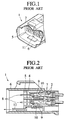
- Figs. 1 and 2 show a connector 1 disclosed in Japanese Patent Unexamined Publication No. 9-106846.
- the connector 1 has a housing 3 and a front holder 5.
- a terminal receiving chamber 2 for receiving a male terminal 7 is formed in the housing 3.
- the front holder 5 is inserted into an opposing surface 4 from above the opposing surface 4 to an opposing connector (not shown) within the housing 3, and prevents the male terminal 7 from coming out from the inner portion of the terminal receiving chamber 2.
- a hood portion 6 extending from an outer peripheral end of the opposing surface 4 and inserting the opposing connector is integrally formed.
- a connecting portion 8 of the male terminal 7 is projected within the hood portion 6.
- a removing jig 12 is inserted from an opening portion 11 for inserting the removing jig formed in the front holder 5, a front end of the removing jig 12 is hooked to the front holder 5 and the front holder 5 is drawn. Accordingly, the front holder 5 is drawn out from the housing 3.
- the front end portion of the removing jig 12 may be erroneously brought into contact with the inner peripheral surface of the hood portion 6.
- the removing jig 12 is moved toward the opening portion 11 with bringing the front end portion of the removing jig 12 into contact with the inner peripheral surface of the hood portion 6, there is a risk of injuring the inner peripheral surface of the hood portion 6 by the front end portion of the removing jig 12.
- an object of the present invention is to provide a connector which can easily and certainly guide a removing jig to a housing within a front holder and can easily remove the front holder from the housing.
- a connector comprising:
- the jig is guided to the holder at the first position by the rib and is operated from above the opposing surface. At this time, since moving range of the jig is restricted by the rig, the jig is prevented from being brought into contact with the other portion such as the housing or the like.
- the other portions such as the housing or the like are not injured by the jig, so that the jig is easily and certainly guided to the holder at the first position, thereby easily removing the holder from the housing.
- FIG. 3 is a partly broken perspective view which shows an inner portion of a connector 13 in accordance with this embodiment at a time of taking out a front holder 14 from the inner portion of the connector 13
- Fig. 4 is a perspective view which shows a state of inserting a removing jig 15 in order to take out the front holder 14 from the connector 13
- Fig. 5 is an exploded perspective view which shows the connector 13 and the front holder 14 attached to the connector 13.
- a movement toward an opposing surface 19 is set to be a forward movement and a movement apart from the opposing surface 19 is set to be a backward movement.
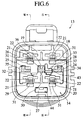
- the connector 13 has a housing 18 fitted to an opposing connector (not shown), the front holder 14 for fixing a terminal detachably held to the housing 18, a rib 24 integrally provided in the housing 18 and three auxiliary ribs 25, 26 and 27.
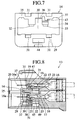
- the housing 13 includes a plurality of terminal receiving chambers 17 (refer to Figs. 8 and 9) receiving terminals 16, an opposing surface 19 to the opposing connector fitted to the housing 13, a holder receiving portion 45 and a waterproof hood portion 20 extending from a peripheral edge of the opposing surface 19.
- the holder receiving portion 45 has an opening 47 to the opposing surface 19.
- the hood portion 20 defines a space above the opposing surface 19 of the front holder 14, and gives an influence to a moving operation of the front holder 19 and an operation of the removing jig 15 from above the opposing surface 19 mentioned below.
- the front holder 14 moves toward near to the opposing surface 19 from above the opposing surface 19, the front holder 14 is inserted into the holder receiving portion 45 from the opening 47 and is disposed at a regular engaging position (a first position).
- the front holder 14 at the regular engaging position prevents the terminal 16 from coming out from the terminal receiving chamber 17.
- the rib 24 and the auxiliary ribs 25, 26 and 27 project from a bottom surface 49 (refer to Fig. 8) opposing to the opening 47 of the holder receiving chamber 45, and extend within the hood portion 20.
- the rib 24 and the auxiliary rib 25 have a cross section formed substantially in an L shape, and the auxiliary ribs 26 and 27 have a cross section formed substantially in a U shape.
- the rib 24 and the auxiliary ribs 25, 26 and 27 are substantially in parallel with each other and extend substantially in a perpendicular manner to the opposing surface 19.
- the auxiliary rib 26 is disposed substantially in a center of the hood portion 20.
- the rib 24 and the auxiliary rib 25 are positioned on a plane passing through the center auxiliary rib 26, and the center auxiliary rib 26 is positioned between the rib 24 and the auxiliary rib 25.
- the auxiliary rib 27 is positioned on the other plane passing through the center auxiliary rib 26 and substantially perpendicular to the plane mentioned above.
- the rib 24 and the auxiliary ribs 25, 26 and 27 guides the front holder 14 toward a regular engaging position within the housing 18.
- An inner upper surface of the rib 24 guides the removing jig 15 for removing the front holder 14 toward the front holder 14 at the regular engaging position.
- the terminal 16 has a connecting portion 16a electrically connected with an opposing terminal in the front end thereof.
- the connecting portion 16a projects within the hood portion 20 when the terminal 16 is received in the terminal receiving chamber 17.
- the housing 18 is provided with a flexible engaging arm 22 projecting from the bottom surface 49 of the holder receiving portion 45 and facing to the terminal receiving chamber 17.
- the engaging arm 22 is positioned between the terminal receiving chamber 17 and the holder receiving portion 45.
- the engaging arm 22 has a terminal holding projection 21 engaging with the terminal 16 received within the terminal receiving chamber 17 in the front end thereof. When the terminal holding projection 21 of the engaging arm 22 engages with the terminal 16, the terminal 16 is prevented from coming out from the inner portion of the terminal receiving chamber 17.
- a portion positioned in opposite to the terminal holding projection 21 serves as a space 23 allowing the engaging arm 22 to elastically deform.
- the front holder 14 is provided with a rectangular parallelepiped main body 29, rib insertion holes 30 and 44 extending through the main body 29 and deformation restricting portions 31 and 31 (refer to Figs. 8 and 9).
- the deformation restricting portion 31 is inserted into the deformation allowing space 23 as the front holder 14 moves forward to the regular engaging position and restricts the deformation of the engaging arm 22.
- a temporary engaging arm (a second arm) 32 supporting the front holder 14 at a temporary engaging position (a second position) with respect to the housing 18 and a regular engaging arm (a first arm) 33 supporting the front holder 14 at a regular engaging position are provided on the inner surface of the rib insertion hole 30.
- the rib insertion hole 30 has rib insertion portions 34 and 35 inserting the rib 24 and the auxiliary rib 25 in both side portions, and has a center rib insertion portion 36 inserting the center auxiliary rib 26 in the center portion.
- the deformation restricting portion 31 is inserted into the deformation allowing space 23 as the front holder 14 moves forward. When the front holder 14 is disposed at the regular engaging position, the deformation restricting portion 31 is inserted into the deformation allowing space 23, so that the deformation of the engaging arm 22 is prevented. When the front holder 14 is disposed at the temporary engaging position, the deformation restricting portion 31 comes out from the deformation allowing space 23, so that the deformation of the engaging arm is allowed.
- the temporary engaging arm 32 is projected from the inner surface 37 of the rib insertion hole 30 toward in a direction that the front holder 14 moves forward.
- a hook portion 38 engageable with a temporary engaging portion (a second engaging portion) 39 provided on the housing 18 is provided in the front end portion of the temporary engaging arm 32.
- the front holder 14 is supported at the temporary engaging position with respect to the housing 18 by an engagement between the hook portion 38 and the temporary engaging portion 39, thereby preventing the front holder 14 from coming out from the housing 18.
- the deformation restricting portion 31 is out from the deformation allowing space 23.
- the regular engaging arm 33 is projected from the inner surface 37 of the rib insertion hole 30 toward in a direction that the front holder 14 moves backward, and is adjacent to the temporary engaging arm 32.
- a protrusion portion 40 engageable with a regular engaging portion (a first engaging portion) 41 provided on the housing 18 is projected in the front end portion of the regular engaging arm 33.
- the front holder 14 is supported at the regular engaging position with respect to the housing 18 by an engagement between the protrusion 40 and the regular engaging portion 41 (refer to a two-dot chain line in Fig. 9). In this state, as mentioned above, the deformation restricting portion 31 is inserted into the deformation allowing space 23.
- Inclined surfaces 42a and 42b are formed in both sides of the protrusion 40.
- the regular engaging arm 33 is bent so that one inclined surface 42a rides over the regular engaging portion 41 and the front holder 14 moves forward to the regular engaging position.
- the other inclined surface 42b is brought into contact with the regular engaging portion 41, and the front holder 14 is held at the regular engaging position.
- an engagement removing projection 43 is projected to a portion between the regular engaging arm 33 and the rib insertion portion 34.
- the front end portion 15a of the removing jig 15 is engaged with the engagement removing projection 43.
- the engagement removing projection 43 corresponds to the removing jig guiding portion 28 on the upper surface inside the rib 24, and is structured such as to easily engage the front end portion 15a of the removing jig 15 guided by the rib 24 to the engagement removing projection 43.
- the front ends of the rib 24 and the auxiliary ribs 25, 26 and 27 are respectively inserted into the rib insertion portions 34, 35, 36 and 44 of the front holder 14.
- the front holder 14 is moved forward toward the opposing surface 19.
- the rib 24 and the auxiliary ribs 25, 26 and 27 precisely guide the front holder 14 toward the temporary engaging position and the regular engaging position.
- the front holder 14 moves with respect to the opposing surface 19 substantially in a parallel state. For this reason, the pressing force is applied to the front holder 14 substantially in an even manner.
- the temporary engaging arm 32 is elastically deformed, and the hook portion 38 rides over and is engaged with the temporary engaging portion 39.
- the front holder 14 is substantially half inserted into the holder receiving portion 45 and then reaches the temporary engaging position.
- the one inclined surface 42a of the protrusion 40 in the regular engaging arm 33 is brought into contact with the regular engaging portion 41.
- the front holder 14 is moved forward without affected by the hood portion 20, and is supported to the housing 18 at the temporary engaging position. Further, in this state, the deformation restricting portion 31 of the front holder 14 is not inserted into the deformation allowing space 23.
- the regular engaging arm 33 When the front holder 14 at the temporary engaging position is further pressed forward, the regular engaging arm 33 is elastically deformed, the inclined surface 42a rides over the regular engaging portion 41, and the inclined surface 42b is engaged with the regular engaging portion 41.
- the front holder 14 is sufficiently inserted into the holder receiving portion 45 and is supported to the housing 18 at the regular engaging position. Further, in this state, the deformation restricting portion 31 is inserted into the deformation allowing space 23, and the deformation of the engaging arm 22 is restricted. Accordingly, the terminal 16 is received within the terminal receiving chamber 17 in a state of being doubly engaged. Still further, in this state, the hook portion 38 of the temporary engaging arm 32 is apart from the temporary engaging portion 39.
- the front end portion 15a of the removing jig 15 is inserted into the hood portion 20 with being brought into contact with the upper surface inside the rib 24. Accordingly, the front end portion 15a of the removing jig 15 is guided to the lower portion of the engagement removing projection 43 in the front holder 14 by the rib 24 without affected by the hood portion 20, and in this state, the front end portion 15a of the removing jig 15 is engaged with the engagement removing projection 43.
- the front holder 14 is moved to the temporary engaging position from the regular engaging position.
- the inclined surface 42b of the regular engaging arm 33 rides over the regular engaging portion 41, so that a supporting state at the regular engaging position is removed.
- the hook portion 38 of the temporary engaging arm 32 is engaged with the temporary engaging portion 39, and the front holder 14 is supported at the temporary engaging position.
- the front holder 14 is prevented from inclining and coming down within the hood portion 20 at a time of forward and backward movement of the front holder 14, so that the front holder 14 can easily move without affected by the hood portion 20.
- the front holder 14 moves substantially in parallel to the opposing surface 19 by a plurality of auxiliary ribs 25, 26 and 27. For this reason, balanced pressing force to the front holder 14 and balanced drawing force by the removing jig 15 are evenly applied to the front holder 14, so that the front holder 14 can be further securely prevented from inclining and coming down within the hood portion 20.
- the removing jig guiding portion 28 for guiding the front end portion 15a of the removing jig 15 to the engagement removing position (the lower portion of the engagement removing projection 43) in the rib 24, at a time of engaging the front end portion 15a of the removing jig 15 with the engagement removing projection 43 of the front holder 14, the front end portion of the removing jig 15 is not slid on the inner peripheral surface of the hood portion 20, thereby not injuring the seal member (not shown) provided in the inner peripheral surface of the hood portion 20 or the housing 18.
Landscapes
- Connector Housings Or Holding Contact Members (AREA)
Applications Claiming Priority (3)
| Application Number | Priority Date | Filing Date | Title |
|---|---|---|---|
| JP118423/97 | 1997-05-08 | ||
| JP11842397 | 1997-05-08 | ||
| JP11842397A JP3495881B2 (ja) | 1997-05-08 | 1997-05-08 | コネクタ |
Publications (3)
| Publication Number | Publication Date |
|---|---|
| EP0877447A2 true EP0877447A2 (de) | 1998-11-11 |
| EP0877447A3 EP0877447A3 (de) | 2001-03-28 |
| EP0877447B1 EP0877447B1 (de) | 2007-12-12 |
Family
ID=14736283
Family Applications (1)
| Application Number | Title | Priority Date | Filing Date |
|---|---|---|---|
| EP98107825A Expired - Lifetime EP0877447B1 (de) | 1997-05-08 | 1998-04-29 | Verbinder |
Country Status (4)
| Country | Link |
|---|---|
| US (1) | US5944558A (de) |
| EP (1) | EP0877447B1 (de) |
| JP (1) | JP3495881B2 (de) |
| DE (1) | DE69838828T2 (de) |
Cited By (3)
| Publication number | Priority date | Publication date | Assignee | Title |
|---|---|---|---|---|
| EP1005110A3 (de) * | 1998-11-25 | 2001-09-12 | Yazaki Corporation | Steckvebinder mit Verriegelungsglied |
| EP1162704A1 (de) * | 2000-06-08 | 2001-12-12 | Sumitomo Wiring Systems, Ltd. | Verbinder und Verfahren zum Trennen von Gehäusen |
| WO2012063457A1 (en) * | 2010-11-12 | 2012-05-18 | Yazaki Corporation | Holder lock structure |
Families Citing this family (10)
| Publication number | Priority date | Publication date | Assignee | Title |
|---|---|---|---|---|
| JP3397298B2 (ja) * | 1998-08-20 | 2003-04-14 | 住友電装株式会社 | コネクタ |
| JP3745608B2 (ja) * | 2000-09-27 | 2006-02-15 | 矢崎総業株式会社 | フロントホルダの係止構造 |
| JP3755644B2 (ja) * | 2000-11-01 | 2006-03-15 | 住友電装株式会社 | コネクタ |
| JP3674774B2 (ja) * | 2001-04-03 | 2005-07-20 | 住友電装株式会社 | コネクタ |
| JP2003045572A (ja) * | 2001-08-03 | 2003-02-14 | Sumitomo Wiring Syst Ltd | コネクタ |
| US6755688B2 (en) * | 2002-03-18 | 2004-06-29 | Tyco Electronics Corporation | Terminal position device apparatus, methods and articles of manufacture for securing sealed male connectors |
| JP4755940B2 (ja) * | 2006-05-23 | 2011-08-24 | 矢崎総業株式会社 | コネクタ |
| US7682191B2 (en) * | 2007-08-10 | 2010-03-23 | Yazaki Corporation | Connector |
| US9276345B2 (en) * | 2012-03-16 | 2016-03-01 | Delphi International Operations Luxembourg S.A.R.L. | Electrical connector |
| JP2021136187A (ja) | 2020-02-28 | 2021-09-13 | 住友電装株式会社 | コネクタ |
Family Cites Families (7)
| Publication number | Priority date | Publication date | Assignee | Title |
|---|---|---|---|---|
| JP2514192Y2 (ja) * | 1991-10-18 | 1996-10-16 | 矢崎総業株式会社 | コネクタ |
| JP2725754B2 (ja) * | 1993-08-06 | 1998-03-11 | 矢崎総業株式会社 | フロント部材を有するコネクタ |
| ES2112148B1 (es) * | 1995-03-07 | 1998-11-16 | Mecanismos Aux Ind | Disposicion de seguridad mejorada aplicable a conectores. |
| JPH0945411A (ja) * | 1995-07-31 | 1997-02-14 | Yazaki Corp | ホルダ付コネクタ |
| JP3188384B2 (ja) * | 1995-10-09 | 2001-07-16 | 矢崎総業株式会社 | コネクタ装置 |
| JP3097825B2 (ja) * | 1995-10-20 | 2000-10-10 | 矢崎総業株式会社 | コネクタ装置 |
| DE29517133U1 (de) * | 1995-10-28 | 1997-02-27 | Robert Bosch Gmbh, 70469 Stuttgart | Vierpoliger elektrischer Steckverbinder |
-
1997
- 1997-05-08 JP JP11842397A patent/JP3495881B2/ja not_active Expired - Fee Related
-
1998
- 1998-04-29 EP EP98107825A patent/EP0877447B1/de not_active Expired - Lifetime
- 1998-04-29 DE DE69838828T patent/DE69838828T2/de not_active Expired - Fee Related
- 1998-05-05 US US09/072,049 patent/US5944558A/en not_active Expired - Fee Related
Cited By (7)
| Publication number | Priority date | Publication date | Assignee | Title |
|---|---|---|---|---|
| EP1005110A3 (de) * | 1998-11-25 | 2001-09-12 | Yazaki Corporation | Steckvebinder mit Verriegelungsglied |
| US6416365B1 (en) | 1998-11-25 | 2002-07-09 | Yazaki Corporation | Connector containing front holder |
| EP1162704A1 (de) * | 2000-06-08 | 2001-12-12 | Sumitomo Wiring Systems, Ltd. | Verbinder und Verfahren zum Trennen von Gehäusen |
| US6416344B2 (en) | 2000-06-08 | 2002-07-09 | Sumitomo Wiring Systems, Ltd. | Connector and a method for detaching housings thereof |
| WO2012063457A1 (en) * | 2010-11-12 | 2012-05-18 | Yazaki Corporation | Holder lock structure |
| KR101389725B1 (ko) * | 2010-11-12 | 2014-04-28 | 야자키 소교 가부시키가이샤 | 홀더 잠금 구조물 |
| US8926364B2 (en) | 2010-11-12 | 2015-01-06 | Yazaki Corporation | Holder lock structure |
Also Published As
| Publication number | Publication date |
|---|---|
| EP0877447A3 (de) | 2001-03-28 |
| DE69838828T2 (de) | 2008-11-27 |
| JP3495881B2 (ja) | 2004-02-09 |
| US5944558A (en) | 1999-08-31 |
| DE69838828D1 (de) | 2008-01-24 |
| JPH10308249A (ja) | 1998-11-17 |
| EP0877447B1 (de) | 2007-12-12 |
Similar Documents
| Publication | Publication Date | Title |
|---|---|---|
| KR101142646B1 (ko) | 방수 커넥터 | |
| US5944558A (en) | Connector with projected rib to guide the holder and the jig to control the connectivity of the terminal | |
| EP0788193A2 (de) | Elektrischer Verbinder | |
| EP3955394A1 (de) | Verbinder | |
| US11189956B2 (en) | Liquid-tight movable connector | |
| JP2001244025A (ja) | コネクタ嵌合構造 | |
| JPH09320672A (ja) | コネクタ | |
| JP2002305052A (ja) | コネクタ | |
| EP1033788B1 (de) | Verbinder mit Sekundärverriegelung | |
| JPH0757815A (ja) | 防水コネクタ | |
| EP0740368A2 (de) | Rohrförmige Haltevorrichtung | |
| EP0902504B1 (de) | Verbinder mit Verriegelungsglied | |
| KR100615894B1 (ko) | 커넥터의 하우징 및 이를 이용한 커넥터 | |
| JPH04233176A (ja) | プラグコネクタ | |
| CN114628937B (zh) | 连接器 | |
| JP2825445B2 (ja) | コネクタ | |
| EP0506075A2 (de) | Montagestruktur für ein Distanzstück eines Verbinders | |
| US6537108B2 (en) | Retaining structure of front holder to connector housing | |
| JP2002246099A (ja) | コネクタ | |
| JPH11121080A (ja) | 合体式コネクタ | |
| CN112563834B (zh) | 连接器 | |
| CN112688105B (zh) | 连接器 | |
| JP4158686B2 (ja) | ロック構造 | |
| JP2002033149A (ja) | コネクタ | |
| JP3792736B2 (ja) | 防水コネクタ |
Legal Events
| Date | Code | Title | Description |
|---|---|---|---|
| PUAI | Public reference made under article 153(3) epc to a published international application that has entered the european phase |
Free format text: ORIGINAL CODE: 0009012 |
|
| 17P | Request for examination filed |
Effective date: 19980429 |
|
| AK | Designated contracting states |
Kind code of ref document: A2 Designated state(s): BE DE ES FR GB IT SE |
|
| AX | Request for extension of the european patent |
Free format text: AL;LT;LV;MK;RO;SI |
|
| PUAL | Search report despatched |
Free format text: ORIGINAL CODE: 0009013 |
|
| AK | Designated contracting states |
Kind code of ref document: A3 Designated state(s): AT BE CH CY DE DK ES FI FR GB GR IE IT LI LU MC NL PT SE |
|
| AX | Request for extension of the european patent |
Free format text: AL;LT;LV;MK;RO;SI |
|
| AKX | Designation fees paid |
Free format text: BE DE ES FR GB IT SE |
|
| 17Q | First examination report despatched |
Effective date: 20050601 |
|
| RAP1 | Party data changed (applicant data changed or rights of an application transferred) |
Owner name: YAZAKI CORPORATION |
|
| GRAP | Despatch of communication of intention to grant a patent |
Free format text: ORIGINAL CODE: EPIDOSNIGR1 |
|
| GRAC | Information related to communication of intention to grant a patent modified |
Free format text: ORIGINAL CODE: EPIDOSCIGR1 |
|
| GRAS | Grant fee paid |
Free format text: ORIGINAL CODE: EPIDOSNIGR3 |
|
| GRAA | (expected) grant |
Free format text: ORIGINAL CODE: 0009210 |
|
| AK | Designated contracting states |
Kind code of ref document: B1 Designated state(s): BE DE ES FR GB IT SE |
|
| REG | Reference to a national code |
Ref country code: GB Ref legal event code: FG4D |
|
| REF | Corresponds to: |
Ref document number: 69838828 Country of ref document: DE Date of ref document: 20080124 Kind code of ref document: P |
|
| PG25 | Lapsed in a contracting state [announced via postgrant information from national office to epo] |
Ref country code: SE Free format text: LAPSE BECAUSE OF FAILURE TO SUBMIT A TRANSLATION OF THE DESCRIPTION OR TO PAY THE FEE WITHIN THE PRESCRIBED TIME-LIMIT Effective date: 20080312 |
|
| ET | Fr: translation filed | ||
| PG25 | Lapsed in a contracting state [announced via postgrant information from national office to epo] |
Ref country code: ES Free format text: LAPSE BECAUSE OF FAILURE TO SUBMIT A TRANSLATION OF THE DESCRIPTION OR TO PAY THE FEE WITHIN THE PRESCRIBED TIME-LIMIT Effective date: 20080323 |
|
| PG25 | Lapsed in a contracting state [announced via postgrant information from national office to epo] |
Ref country code: BE Free format text: LAPSE BECAUSE OF FAILURE TO SUBMIT A TRANSLATION OF THE DESCRIPTION OR TO PAY THE FEE WITHIN THE PRESCRIBED TIME-LIMIT Effective date: 20071212 |
|
| PLBE | No opposition filed within time limit |
Free format text: ORIGINAL CODE: 0009261 |
|
| STAA | Information on the status of an ep patent application or granted ep patent |
Free format text: STATUS: NO OPPOSITION FILED WITHIN TIME LIMIT |
|
| 26N | No opposition filed |
Effective date: 20080915 |
|
| GBPC | Gb: european patent ceased through non-payment of renewal fee |
Effective date: 20080429 |
|
| PG25 | Lapsed in a contracting state [announced via postgrant information from national office to epo] |
Ref country code: GB Free format text: LAPSE BECAUSE OF NON-PAYMENT OF DUE FEES Effective date: 20080429 |
|
| PGFP | Annual fee paid to national office [announced via postgrant information from national office to epo] |
Ref country code: FR Payment date: 20090417 Year of fee payment: 12 Ref country code: DE Payment date: 20090428 Year of fee payment: 12 |
|
| REG | Reference to a national code |
Ref country code: FR Ref legal event code: ST Effective date: 20101230 |
|
| PG25 | Lapsed in a contracting state [announced via postgrant information from national office to epo] |
Ref country code: IT Free format text: LAPSE BECAUSE OF NON-PAYMENT OF DUE FEES Effective date: 20080430 Ref country code: DE Free format text: LAPSE BECAUSE OF NON-PAYMENT OF DUE FEES Effective date: 20101103 |
|
| PG25 | Lapsed in a contracting state [announced via postgrant information from national office to epo] |
Ref country code: FR Free format text: LAPSE BECAUSE OF NON-PAYMENT OF DUE FEES Effective date: 20100430 |