EP0877875B1 - Actionneur s'ajustant automatiquement a des charges laterales par pivotement interne - Google Patents
Actionneur s'ajustant automatiquement a des charges laterales par pivotement interne Download PDFInfo
- Publication number
- EP0877875B1 EP0877875B1 EP97904878A EP97904878A EP0877875B1 EP 0877875 B1 EP0877875 B1 EP 0877875B1 EP 97904878 A EP97904878 A EP 97904878A EP 97904878 A EP97904878 A EP 97904878A EP 0877875 B1 EP0877875 B1 EP 0877875B1
- Authority
- EP
- European Patent Office
- Prior art keywords
- housing
- gear nut
- linear actuator
- lever
- spherical
- Prior art date
- Legal status (The legal status is an assumption and is not a legal conclusion. Google has not performed a legal analysis and makes no representation as to the accuracy of the status listed.)
- Expired - Lifetime
Links
- 230000000712 assembly Effects 0.000 claims description 14
- 238000000429 assembly Methods 0.000 claims description 14
- 230000007246 mechanism Effects 0.000 claims description 5
- 239000004033 plastic Substances 0.000 description 6
- 239000002184 metal Substances 0.000 description 5
- 238000007373 indentation Methods 0.000 description 3
- 238000000034 method Methods 0.000 description 3
- 230000004048 modification Effects 0.000 description 3
- 238000012986 modification Methods 0.000 description 3
- 238000009434 installation Methods 0.000 description 2
- 238000003754 machining Methods 0.000 description 2
- 238000000465 moulding Methods 0.000 description 2
- 238000009987 spinning Methods 0.000 description 2
- 239000004677 Nylon Substances 0.000 description 1
- 241000425571 Trepanes Species 0.000 description 1
- 239000000853 adhesive Substances 0.000 description 1
- 230000001070 adhesive effect Effects 0.000 description 1
- 230000005540 biological transmission Effects 0.000 description 1
- 238000006243 chemical reaction Methods 0.000 description 1
- 230000006835 compression Effects 0.000 description 1
- 238000007906 compression Methods 0.000 description 1
- 230000007423 decrease Effects 0.000 description 1
- 230000005484 gravity Effects 0.000 description 1
- 238000001746 injection moulding Methods 0.000 description 1
- 230000007257 malfunction Effects 0.000 description 1
- 238000004519 manufacturing process Methods 0.000 description 1
- 239000000463 material Substances 0.000 description 1
- 230000013011 mating Effects 0.000 description 1
- 229920001778 nylon Polymers 0.000 description 1
- 230000010355 oscillation Effects 0.000 description 1
- 239000012255 powdered metal Substances 0.000 description 1
- 230000001681 protective effect Effects 0.000 description 1
- 238000010079 rubber tapping Methods 0.000 description 1
Images


Classifications
-
- F—MECHANICAL ENGINEERING; LIGHTING; HEATING; WEAPONS; BLASTING
- F16—ENGINEERING ELEMENTS AND UNITS; GENERAL MEASURES FOR PRODUCING AND MAINTAINING EFFECTIVE FUNCTIONING OF MACHINES OR INSTALLATIONS; THERMAL INSULATION IN GENERAL
- F16H—GEARING
- F16H25/00—Gearings comprising primarily only cams, cam-followers and screw-and-nut mechanisms
- F16H25/18—Gearings comprising primarily only cams, cam-followers and screw-and-nut mechanisms for conveying or interconverting oscillating or reciprocating motions
- F16H25/20—Screw mechanisms
- F16H25/24—Elements essential to such mechanisms, e.g. screws, nuts
- F16H25/2454—Brakes; Rotational locks
-
- B—PERFORMING OPERATIONS; TRANSPORTING
- B60—VEHICLES IN GENERAL
- B60N—SEATS SPECIALLY ADAPTED FOR VEHICLES; VEHICLE PASSENGER ACCOMMODATION NOT OTHERWISE PROVIDED FOR
- B60N2/00—Seats specially adapted for vehicles; Arrangement or mounting of seats in vehicles
- B60N2/02—Seats specially adapted for vehicles; Arrangement or mounting of seats in vehicles the seat or part thereof being movable, e.g. adjustable
- B60N2/22—Seats specially adapted for vehicles; Arrangement or mounting of seats in vehicles the seat or part thereof being movable, e.g. adjustable the back-rest being adjustable
- B60N2/23—Seats specially adapted for vehicles; Arrangement or mounting of seats in vehicles the seat or part thereof being movable, e.g. adjustable the back-rest being adjustable by linear actuators, e.g. linear screw mechanisms
- B60N2/233—Seats specially adapted for vehicles; Arrangement or mounting of seats in vehicles the seat or part thereof being movable, e.g. adjustable the back-rest being adjustable by linear actuators, e.g. linear screw mechanisms by linear screw mechanisms
-
- Y—GENERAL TAGGING OF NEW TECHNOLOGICAL DEVELOPMENTS; GENERAL TAGGING OF CROSS-SECTIONAL TECHNOLOGIES SPANNING OVER SEVERAL SECTIONS OF THE IPC; TECHNICAL SUBJECTS COVERED BY FORMER USPC CROSS-REFERENCE ART COLLECTIONS [XRACs] AND DIGESTS
- Y10—TECHNICAL SUBJECTS COVERED BY FORMER USPC
- Y10T—TECHNICAL SUBJECTS COVERED BY FORMER US CLASSIFICATION
- Y10T74/00—Machine element or mechanism
- Y10T74/18—Mechanical movements
- Y10T74/18568—Reciprocating or oscillating to or from alternating rotary
- Y10T74/18576—Reciprocating or oscillating to or from alternating rotary including screw and nut
- Y10T74/1868—Deflection related
-
- Y—GENERAL TAGGING OF NEW TECHNOLOGICAL DEVELOPMENTS; GENERAL TAGGING OF CROSS-SECTIONAL TECHNOLOGIES SPANNING OVER SEVERAL SECTIONS OF THE IPC; TECHNICAL SUBJECTS COVERED BY FORMER USPC CROSS-REFERENCE ART COLLECTIONS [XRACs] AND DIGESTS
- Y10—TECHNICAL SUBJECTS COVERED BY FORMER USPC
- Y10T—TECHNICAL SUBJECTS COVERED BY FORMER US CLASSIFICATION
- Y10T74/00—Machine element or mechanism
- Y10T74/18—Mechanical movements
- Y10T74/18568—Reciprocating or oscillating to or from alternating rotary
- Y10T74/18576—Reciprocating or oscillating to or from alternating rotary including screw and nut
- Y10T74/18704—Means to selectively lock or retard screw or nut
Definitions
- the present invention relates to seat actuators, primarily those used for vehicle seat recliners and possibly seat positioners.
- Linear actuators for allowing vehicle seats to move and the seat back to pivot are becoming increasingly complicated.
- One proposed linear actuator uses a leadscrew or threaded shaft. As it moves forward or backward axially due to the seat being reclined, a threaded gear nut or spin nut rotates about the leadscrew.
- the spin nut has a clutch that disengages the leadscrew when the user manually activates a recline lever. When the user releases the recline lever the clutch engages the shaft and prevents rotation of the spinning nut. That locks the leadscrew from further axial movement.
- FR 1407810 A discloses a screw and nut transmission arrangement which enables limited oscillation of the axis of the screw around a mean position.
- the nut element and housing are fixed so that they are not rotatable relative to one another.
- the principal object of the present invention is to disclose and provide a high-load linear actuator that compensates for installation and other misalignments, with a low frictional resistance to pivoting.
- the present invention provides a linear actuator, comprising: a housing; a leadscrew traversing the housing; a gear nut located in the housing and mounted on the leadscrew so as to be rotatable in response to axial movement of the leadscrew relative to the gear nut; and first and second bearing surfaces in said housing; wherein: said gear nut has bearing surfaces for engaging said housing bearing surfaces such that the gear nut is capable of pivoting relative to said housing to change the axis of rotation of the gear nut; and said gear nut is rotatable relative to said housing; characterised in that: the housing bearing surfaces (30, 46; 150, 152) have a curvature which is differentto that ofthe gear nut bearing surfaces (30, 46;147, 149).
- the gear nut rotates and a ball, which is manually controlled by the user of the seat, moves in a slot radially to the gear nut.
- the ball can engage ordisengage castellations on the gear nut.
- the ball engages a gear nut castellation.
- the nut does not turn because the slot prevents the ball from rotating with the gear nut. Therefore, the leadscrew cannot move axially and the actuator is locked.
- the gear nut can pivot up, down, to the side or at an angle within the housing. Therefore, if the leadscrew is not aligned with the housing, the leadscrew pivots the gear nut so that the gear nut remains aligned with the leadscrew.
- the gear nut has spherical ends or inserts with spherical end surfaces, and the housing has inner walls that are spherical. The inserts or spherical radii of the gear nut itself, against the inner walls, therefore, allow gear nut rotation, and they can slide relative to each other so that the gear nut can follow the leadscrew's orientation. The spherical radii, in contact with each other also allow the gear nut to spin.
- the gear nut is mounted for rotation on a conical support surface. This arrangement results in a relatively small gear nut/support surface contact area.
- the actuator has a two-piece housing.
- the housing sections can be tightened relative to each other to squeeze against the spherical gear nut or its inserts. This minimizes "chuck,” which is undesired movement of the leadscrew while the unit is locked.
- a housing may be provided with a threaded opening and cap arrangement that performs substantially the same function.
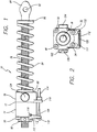
- the linear actuator 10 of the present invention includes a housing 12 (FIGS. 1 and 3).
- the housing is formed of plastic, but it may also be formed of die cast metal or of some metal and some plastic sections.
- Housing 12 has two major sections, a plastic main section 14 and a metal mounting block 16 (FIGS. 1 and 3).
- Upstanding wall 18 and end wall 26 form main section 14.
- the end wall's inner surface 30 is spherical.
- Upstanding wall 18 forms a cylinder at the open end 34 of the main housing (FIGS. 3 and 4), which curves into the spherical end 30 (FIG. 3).
- End wall 26 also has a tapered hole 32 extending through it (FIG. 3).
- upstanding wall 18 has a circumferential projection 36.
- projection 36 projects into a corresponding circumferential groove or trepan 40 on the mounting block (FIG. 3).
- An arrangement other than circumferential projections and grooves can be used to mount the housing and the mounting block together
- short pegs may fit into indentations.
- Small springs (not shown) could mount in a groove or indentation to bias the housing and mounting block apart.
- the mounting block also has a spherical inner surface 46 (FIG. 3) and a central tapered hole or bore 44.
- Surfaces 30 and 46 are approximately the same or are part of the same sphere. That is, the surfaces in theory have a common center and nearly, if not, equal radii.
- bolts 48, 50, 52 and 54 extend through bores 56, 58, 60 and 62 (FIG. 4) in the mounting block.
- the bolts thread into threaded bores (not shown) in the end of the mounting block. Rivets, self-tapping screws and similar fasteners could replace the bolts and threaded bores.
- the exemplary embodiment uses four bolts, but more or fewer could be used.
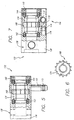
- Gear nut 64 (FIGS. 3 and 4) fits within space 66 inside the open end 34 of main housing 14 and extends between the main housing's spherical wall 30 and the spherical wall 46 of mounting block 16.
- the gear nut is generally cylindrical (FIG. 3) with a larger diameter central ring 68.
- Optional nylon or other low friction annular inserts 70 and 72 attach to the end of the gear nut.
- the inserts are open in their centers and have spherical end surfaces 74 and 76 (FIG. 3). These spherical surfaces conform to spherical walls 30 and 46 of the main housing and mounting block in that all surfaces have nearly the same center and radius. Accordingly, the gear nut can pivot with the longitudinal axis of the leadscrew in any direction within space 66. All spherical walls 30, 46, 70 and 72 should be smooth to reduce friction.
- the gear nut could be a powdered metal part, metal injection molding or machined to have spherical ends.
- leadscrew 78 has an ACME thread.
- One choice for the leadscrew is 5 / 8 in (16 mm [metric conversions are rounded and approximate]) diameter with a 4 threads per inch pitch and four starts. Only FIG. 3 shows the threads of the leadscrew, and they are not drawn to scale.
- the design of the seat that incorporates the actuator of the present invention determines the leadscrew's length.
- One end of the leadscrew is flattened to form a tang 80 (FIG. 1).
- a center opening 82 in the tang allows that end of the actuator to be attached to part of the seat assembly.
- a return spring 84 which surrounds the leadscrew, extends between washer 86 and wall 88 of mounting block 16. Other arrangements that do not use the washer may be used.
- the spring is in compression to bias the leadscrew to the right in FIG. 1.
- Stop ring 90 is crimped on the left end (FIGS. 1 and 3) of the leadscrew to prevent the leadscrew from being withdrawn from the housing.
- Gear nut 64 is open at 92 at its center. See FIG. 4.
- the gear nut also has internal threads that correspond with the leadscrew's threads.
- inserts 74 and 76 have openings that are aligned with the gear nut's opening so that the leadscrew passes freely through the inserts.
- FIG. 4 shows the ball in the locked position.
- a piston 102 (FIGS. 3 and 4) which is mounted in the housing, has a section with a larger diameter 104 that can be positioned below ball 98.
- FIG. 4 shows that part of the piston passes through part of groove 100.
- a wire 108 attaches to bracket 112 on the left end of housing 12 (FIGS. 1 and 3).
- the bracket pivots on pin or projection 116 on the housing and rests against piston 102 .
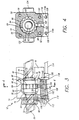
- the bracket has a slot 120 (FIG. 2) that receives wire 108.
- a stop 110 on the end of the wire secures the wire to the bracket.
- leadscrew 78 can move axially.
- spring bias pushes piston 102 to the left (FIG. 3) and returns bracket to its left-most position.
- piston 102 When the piston moves to the left, its raised portion 104 pushes ball 98 into a castellation.
- Fig. 4 shows, ball 98 remains partially within groove 100. Therefore, the ball cannot rotate with the gear. Therefore, when the ball is in a castellation, the ball/groove connection prevents gear nut rotation. This locks the leadscrew.
- Bracket 118 could house a second cable with a second wire 109 to a second actuator. See FIG. 2 which shows 2 stops 110 and 111 on the end of the wires.
- one handle could be within reach of the person sitting in the seat, and the second handle could be within reach of a rear seat passenger or person entering a car who needs to pivot the seat back to enter the rear seat area.
- a pair of bosses 122 and 124 are a part of and project from the sides of mounting block 16 (FIGS. 1, 2 and 4).
- the bosses preferably are metal.
- Each may have a 120° conical indentation 126 (FIG. 2).
- Mounting hardware on the vehicle seat (not shown) accepts and restrains the bosses so that the bosses can pivot while constrained by the hardware. This allows the actuator to pivot about an axis through the bosses.
- any leadscrew misalignment pivots the gear nut with the leadscrew (See FIG. 3) as the spherical surfaces 74 and 76 of inserts 70 and 72 slide along and spin against the spherical inner walls 30 and 46. Therefore, the leadscrew and gear nut remain aligned and do not bind.
- the spherical surfaces 74 and 76 of inserts 70 and 72 must apply proper force to spherical inner walls 30 and 46 . This is accomplished by tightening bolts 48, 50, 52 and 54 or other comparable fasteners properly. Proper tightening minimizes "chuck,” the undesired movement of the leadscrew or gear nut relative to the rest of the locked assembly
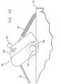
- FIGS. 5-14 Other exemplary embodiments of the present invention are illustrated in FIGS. 5-14.
- a gear nut 134 is located within a housing 136 that includes a main section 138 and a threaded end cap 140 The end cap threads mate with corresponding threads on the inner surface of the main section (threads not shown)
- the gear nut 134 has internal threads which engage a leadscrew 135 (see FIG. 8 - threads not shown) in the manner described above.
- the interior of the housing 136 includes a pair of bearing assemblies 142 and 144 which support the gear nut 134.
- the longitudinal end surfaces 146 and 148 of the gear nut 134 have a curved shape, as do the respective interior surfaces of the bearing assemblies 142 and 144 .
- the curved end surfaces 146 and 148 of the gear nut 134 may be formed through molding, machining or by adding inserts 147 and 149 (as shown) with the appropriate curvature.
- the interior surfaces of the bearing assemblies 142 and 144 are in the form of low friction inserts 150 and 152 that are press-fit into the bearing assemblies. The low friction inserts 150 and 152 rotate with the gear nut 134.
- the remaining portions of the bearing assemblies consist of respective inner races 154 and 156, groups of ball bearings 158 and 160, and outer races 162 and 164.
- the inserts may be eliminated, if desired, and replaced by suitably surfaced inner races.
- the curved end surfaces 146 and 148 of the gear nut 134 define respective spherical surfaces (be they formed by molding, machining or through the use of inserts).
- the surfaces of the inserts 150 and 152 have a conical tapered shape. If the leadscrew is not properly aligned, the spherical surface portions of the gear nut 134 will slide along the respective conical surfaces of the inserts 150 and 152 , thereby maintaining gear nut/leadscrew alignment and preventing binding.
- the spherical surfaces of the gear nut 64 are in contact with housing spherical surfaces 34 and 46.
- the gear nut 134 includes spherical surfaces, while the surfaces of the inserts 150 and 152 have a conical tapered shape.
- the contact area between the gear nut 134 and the bearing assemblies 142 and 144 is, therefore, substantially less than the contact area between the gear nut 64 and the housing surfaces 34 and 46 .
- the contact surface between the gear nut 134 and each of the bearing assemblies 142 and 144 is essentially a thin line which circles the gear nut curved end surfaces 146 and 148.
- the threaded end cap 140 allows the gear nut 134 and bearing assemblies 142 and 144 to be easily placed within the housing main section 138 . Thereafter, the threaded end cap may be used to apply the proper force to the bearing assemblies so as to minimize "chuck.” The end cap 140 may then be locked in place by any suitable method such as, for example, the use of adhesive or deforming small, adjacent portions of the cap 140 and the main body section 138. Such an arrangement is easier to assemble and easier to adjust for friction and chuck than one which relies on tightening bolts to join respective sections of a housing.
- the locking assembly 166 includes a locking lever 170 that rotates with a spindle 172 between an engaged (or locked) orientation and disengaged (or unlocked) orientation.
- the locking lever 170 and spindle 172 are preferably separate structural elements that are connected to one another by any suitable method such as, for example, keying or splining
- the spindle 172 includes splines 173 that are used to attach the spindle to an operating lever or handle (not shown) This spindle and handle arrangement eliminates the need for the wires and cables discussed above.
- one surface of the locking lever 170 engages the castellations 168, while another surface of the locking lever is engaged by a plunger 174 that has a suitable cam surface.
- the plunger 174 is biased in the direction of the locking lever 170 by a spring 176 or other resilient element.
- the plunger 174 and spring 176 maintain the locking lever 170 in the engaged orientation. Operation of the handle (and, therefore, rotation of the spindle 172 ) will overcome the force of the biasing spring 176 and cause the locking lever 170 to move out of engagement with the gear nut 134, thereby allowing the gear nut to rotate.
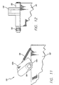
- FIGS. 9-12 Another exemplary locking assembly 178 is shown in FIGS. 9-12.
- a locking lever 180 is pivotably mounted on the exterior of a housing 182 such that one end 180a extends through an opening in the housing.
- the locking lever 180 moves between a locked position where end 180a engages the castellations 168 and an unlocked position where the end is disengaged.
- the locking lever 180 is biased to the locked position by a resilient element, such as a spring 184 (shown in FIGS. 10 and 11) that is attached to the housing 182 and to an end 180b of the lever.
- the lever may be pulled to the unlocked position by a cable (or cables) 186 when mounted for rotation on a rod 187.
- the cable 186 is secured to the locking lever 180 by a ball 189 and is guided by a guide 191.
- the ball 189 prevents the cable 186 from being pulled through the lever 180.
- the lever 180 may be attached to a spindle 188.
- the locking lever 180 will rotate with the spindle 188 when a handle (not shown) is operated.
- the handle may be connected to the spindle 188 through the use of splines 190, or any other suitable fastening device.
- the locking lever 180 may be connected to the spindle 188 in the same or similar manner.
- the present invention may also include a leadscrew guide 192.
- the leadscrew guide 192 guides the leadscrew 135 and helps maintain the alignment thereof.
- the guide may also be used to mount a return spring and prevent the return spring from rubbing against the leadscrew.
- the leadscrew guide 192 acts as a stop to prevent the leadscrew head 194 from moving past the end of the guide.
- the exemplary guide 192 includes an insert portion 194 which is inserted into an aperture in the housing 182 (or 136 ) during assembly.
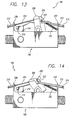
- a locking assembly 196 can be actuated by two cables which approach a linear actuator 198 (preferably one of the actuators described above) from different directions. More specifically, the locking assembly 196 includes a locking lever 200 (preferably of the type shown in FIG. 10) that is biased to the locked position shown in FIG. 13 by a spring 202. This prevents rotation of a gear nut (not shown) within the linear actuator 198.
- the locking lever 200 can be moved to the unlocked position shown in FIG. 14 by a first cable 204 which connects the locking lever to an actuator at a first location.
- the cable 204 is secured to the locking lever 200 by a ball 206 and guided by a guide 208 .
- the cable 204 is also covered by a protective covering, or conduit 210 .
- a second cable 212 and conduit 214 arrangement allows the locking lever 200 to be actuated from a second location.
- One end of the cable 212 is secured to an anchor 216 by a ball 218. From there, the cable 212 passes through an opening in the locking lever 200, through a guide 220, and then on to the second location.
- the guide 220 also holds the conduit 214 and prevents the conduit from moving relative to the actuator while allowing movement of the cable 212 within the conduit.
- a fitting 222 may, if desired, be placed between the end of the conduit 214 and the locking lever 200 in order to protect the end of the conduit from wear. Otherwise, the end of the conduit 214 will abut the locking lever 200.
- the cable 212 and conduit 214 are bent when the locking assembly 196 is in the locked orientation.
- the cable 212 is straightened on both sides of the locking lever (i.e. the slack is removed) when the cable is pulled due to actuation of a handle, lever or other suitable device at the second location. (See FIG. 14.)
- the straightening of the cable 212 causes the conduit 214 to straighten out. As the conduit 214 straightens, it overcomes the biasing force of spring 202 and pushes the locking lever 200 to the unlocked position shown in FIG. 14.
- the conduit 214 is preferably formed at least in part from a plastic material and the stiffness of the conduit must be such that it is flexible enough to bend with the cable 212 under the biasing force of the spring 202 , yet stiff enough to straighten out with the cable when the cable is pulled.
- a locking assembly that can be actuated by two cables which approach a linear actuator from different directions.
- the front seats of automobiles are typically capable of both reclining for passenger comfort and folding forward to allow a passenger in the back seat to exit.
- Use of the locking assembly 196 would allow the seat's linear actuator, which locks the seat in place, to be unlocked from different locations.
- One seat release handle may be located next to the seat cushion of the front seat, While another handle may be located in close proximity to the back seat. As a result, a person sitting in the back seat will be able to release the front seat and exit the vehicle without having to reach forward and find the seat release handle next to the front seat's cushion (which is often blocked from view by the front seat itself).
- the gear nut could be a helical gear that a mating gear or worm could drive. Locking the driving motor would lock the gear nut.
- Another modification concerns the mounting of ball 98 . Instead of relying on gravity to remove the ball from a castellation, the ball could be spring mounted.
Landscapes
- Engineering & Computer Science (AREA)
- General Engineering & Computer Science (AREA)
- Mechanical Engineering (AREA)
- Aviation & Aerospace Engineering (AREA)
- Transportation (AREA)
- Transmission Devices (AREA)
Claims (42)
- Actionneur linéaire, qui comprend :dans lequel :un logement (12, 136) ;une vis mère (78, 135) qui traverse le logement (12, 136) ;un écrou d'engrenage (64, 134) situé dans le logement (12, 136) et monté sur la vis mère (78, 135) de façon à pouvoir être mobile en réponse au mouvement axial de la vis mère (78, 135) par rapport à l'écrou d'engrenage ;et une première et deuxième surfaces d'appui (30, 46; 150, 152) dans ledit logement (12, 136) ;caractérisé en ce que :ledit écrou d'engrenage est mobile par rapport audit logement ;ledit écrou d'engrenage (64, 134) a des surfaces d'appui (74, 76; 147, 149) pour se mettre en prise avec lesdites surfaces d'appui de logement de façon à ce que l'écrou d'engrenage soit capable de pivoter par rapport audit logement (12, 136) afin de changer l'axe de rotation de l'écrou d'engrenage ; etles surfaces d'appui de logement (30, 46; 150, 152) ont une courbure qui est différente de celle des surfaces d'appui d'écrou d'engrenage (30, 46; 147, 149).
- Actionneur linéaire tel que revendiqué à la revendication 1 dans lequel :ledit logement (12, 136) incorpore un espace ouvert (66) au moins partiellement limité par des parois courbes tournées vers l'intérieur (30, 46; 150, 152) ;l'écrou d'engrenage (64, 134) a des parois extérieures courbes (74, 76; 147, 149) ;et au moins une portion de chacune des parois courbes extérieures (74, 76; 147, 149) de l'écrou d'engrenage (64; 134) est dans une relation espacée par rapport à une desdites parois courbes adjacentes tournées vers l'intérieur (30, 46; 150, 152) du logement (12, 136).
- Actionneur linéaire tel que revendiqué à la revendication 2 ou 3 dans lequel les parois courbes du logement (12) et de l'écrou d'engrenage (64) sont sphériques.
- Actionneur linéaire tel que revendiqué à la revendication 1 dans lequel :(a) ledit logement (12, 136) a une section centrale ouverte (66), une paroi d'extrémité ayant une surface sphérique (30) sur au moins une portion de la paroi d'extrémité, un bloc de montage (16) à l'extrémité opposée de la paroi d'extrémité, le bloc de montage ayant une surface sphérique (46) sur au moins une portion du bloc de montage, les surfaces sphériques (30, 46; 150, 152) de la paroi d'extrémité et du bloc de montage se faisant face, la paroi d'extrémité et le bloc de montage ayant chacun un orifice central (32, 44) l'un en face de l'autre ;(b) ledit écrou d'engrenage (64, 134) s'étend entre les surfaces sphériques (30, 46; 150, 152) de la paroi d'extrémité et du bloc de montage (16), l'écrou d'engrenage (64, 134) étant muni d'une ouverture centrale (92) et de surfaces d'extrémité courbes et étant situé à l'intérieur du logement (12, 136) de telle manière qu'au moins une portion de chacune des surfaces d'extrémité courbes soit dans une relation espacée par rapport à la surface sphérique adjacente respective de la paroi d'extrémité ou du bloc de montage ; et(c) ladite vis mère (78, 135) traverse le logement (12, 136) et passe dans l'écrou d'engrenage (64, 134), l'écrou d'engrenage étant appuyé contre les surfaces sphériques (30, 46; 150, 152) et tournant autour de la vis mère (78, 135) en réponse au mouvement axial de la vis mère (78, 135) dans le logement (12, 136) ;(d) l'écrou d'engrenage (64, 134) pouvant pivoter pour changer l'axe de rotation de l'écrou d'engrenage par rapport au logement (12, 136).
- Actionneur linéaire tel que revendiqué à la revendication 4 dans lequel les surfaces d'extrémité courbes de l'écrou d'engrenage (64) comprennent des parois extérieures sphériques (72, 74).
- Actionneur linéaire tel que revendiqué à la revendication 4 ou 5 dans lequel des pièces rapportées forment au moins une paroi extérieure sphérique.
- Actionneur linéaire tel que revendiqué à la revendication 1 dans lequel :ledit logement (12) a une section centrale ouverte, une paroi d'extrémité ayant une surface sphérique sur au moins une portion de la paroi d'extrémité, un bloc de montage (16) à l'extrémité opposée de la paroi d'extrémité, le bloc de montage ayant une surface sphérique sur au moins une portion du bloc de montage (16), les surfaces sphériques (30, 46) de la paroi d'extrémité et du bloc de montage se faisant face, la paroi d'extrémité et le bloc de montage ayant chacun un orifice central (32, 44) l'un en face de l'autre ;ledit écrou d'engrenage (64) s'étend entre les surfaces sphériques (30, 46) de la paroi d'extrémité et du bloc de montage (16), l'écrou d'engrenage étant muni d'une ouverture centrale (92) et de créneaux s'étendant autour de celui-ci ;ladite vis mère (78) passe dans l'écrou d'engrenage (64), l'écrou d'engrenage appuyé contre les surfaces sphériques (30, 46) et tournant autour de la vis mère (78) en réponse au mouvement axial de la vis mère (78) dans le logement (136) ;et ledit actionneur comprend en outre :une rainure ménagée dans le logement (136) s'étendant vers les créneaux ;une boule pouvant se déplacer à l'intérieur de la rainure entre une position faisant partiellement saillie depuis la rainure et s'étendant dans un créneau et une position rétractée depuis un créneau ;et un piston dans le logement (136) qui vient en contact avec la boule, le piston ayant des portions de diamètres différents, le piston se déplaçant dans le logement (136) depuis une position dans laquelle la portion de diamètre plus petit est adjacente à la boule pour permettre à celle-ci de se rétracter depuis un créneau et une portion de plus grand diamètre poussant la boule vers le créneau ;et dans lequel l'écrou d'engrenage (64) pivote pour changer l'axe de rotation de l'écrou d'engrenage par rapport au logement (136).
- Actionneur linéaire tel que revendiqué à la revendication 7 comprenant en outre un ressort dans le logement (12, 136) et relié d'une manière exploitable au piston, le ressort sollicitant le piston pour positionner la portion de plus grand diamètre de façon à venir en contact avec la boule.
- Actionneur linéaire tel que revendiqué dans l'une quelconque des revendications 4 à 8 dans lequel les orifices centraux (32, 44) sont coniques.
- Actionneur linéaire tel que revendiqué à la revendication 1 dans lequel ledit écrou d'engrenage (64; 134) possède une première et deuxième portions d'extrémité longitudinales ayant des surfaces courbes (76, 76; 147, 149) qui définissent une courbure de surface d'extrémité d'écrou d'engrenage ;
et lesdites première et deuxième surfaces d'appui de logement (30, 46; 150, 152) se mettent respectivement en prise avec les première et deuxième surfaces d'extrémité longitudinales (74, 76; 147, 149) de l'écrou d'engrenage (64; 134) de telle manière que l'écrou d'engrenage est capable de pivoter pour changer l'axe de rotation de l'écrou d'engrenage, les surfaces d'appui (30, 46; 150, 152) étant mobiles et définissant une courbure de surface d'appui qui est différente de la courbure de surface d'extrémité d'écrou d'engrenage. - Actionneur linéaire tel que revendiqué à la revendication 1, dans lequel l'une de la courbure de surface d'extrémité d'écrou d'engrenage (147, 149) et la courbure de surface d'appui (150, 152) est en grande partie sphériques et l'autre de la courbure de surface d'extrémité d'écrou d'engrenage et la courbure de surface d'appui est en grande partie conique.
- Actionneur linéaire tel que revendiqué à la revendication 1 ou 11, dans lequel la courbure de surface d'extrémité d'écrou d'engrenage (34, 46; 147, 149) est en grande partie sphérique.
- Actionneur linéaire tel que revendiqué à la revendication 11 ou 12, dans lequel les première et deuxième surfaces d'appui (150, 152) sont associées au premier et deuxième assemblages d'appui (142, 144).
- Actionneur linéaire tel que revendiqué à la revendication 13, dans lequel les premier et deuxième assemblages d'appui (142, 144) incorporent des portions respectives fixes et des portions respectives mobiles.
- Actionneur linéaire tel que revendiqué à la revendication 14, dans lequel les première et deuxième surfaces d'appui (150, 152) comprennent une première et deuxième pièces rapportées (150, 152) qui sont respectivement fixées aux portions mobiles des premier et deuxième assemblages d'appui (142, 144).
- Actionneur linéaire tel que revendiqué à la revendication 1 ou dans l'une quelconque des revendications 11 à 15, dans lequel les première et deuxième portions d'extrémité de l'écrou d'engrenage (134) et les première et deuxième surfaces d'appui (150, 152) définissent des zones de contact respectives entre elles, chaque zone de contact se présentant sous la forme d'une ligne mince qui entoure une portion d'extrémité d'écrou d'engrenage respective.
- Actionneur linéaire tel que revendiqué à la revendication 1 ou dans l'une quelconque des revendications 11 à 16, dans lequel le logement (12, 136) comprend une section principale (138) définissant une ouverture filetée et un chapeau d'extrémité fileté (140) adapté pour se mettre en prise avec l'ouverture et appliquer une force variable sur au moins une de la première surface d'appui (150), la deuxièmes surface d'appui (152), et l'écrou d'engrenage (134).
- Actionneur linéaire tel que revendiqué à la revendication 1, dans lequel :ledit écrou d'engrenage (64, 134) possède une pluralité de créneaux espacés sur son pourtour (94, 168) ;et ledit actionneur comprend en outre un mécanisme de verrouillage (166) incorporant un levier pouvant pivoter (170) adapté pour se déplacer entre une position verrouillée dans laquelle le levier se met en prise avec un des créneaux et une position non verrouillée, et un dispositif de sollicitation (176) adapté pour solliciter le levier vers la position verrouillée.
- Actionneur linéaire tel que revendiqué à la revendication 18, dans lequel le levier (170) est monté sur une tige mobile (172) .
- Actionneur linéaire tel que revendiqué à la revendication 18 ou 19, dans lequel le levier (170) est situé en grande partie à l'intérieur du logement (136).
- Actionneur linéaire tel que revendiqué à la revendication 18, 19 ou 20 dans lequel le dispositif de sollicitation (176) comprend un plongeur (174) adapté pour se mettre en prise avec une portion du levier (170) et un élément résilient (176) adapté pour appliquer une force de sollicitation sur le plongeur.
- Actionneur linéaire tel que revendiqué à la revendication 21, dans lequel le logement (136) incorpore une ouverture de levier, une première portion du levier est située à l'intérieur du logement (136), et une deuxième portion du levier est située à l'extérieur du logement (136).
- Actionneur linéaire tel que revendiqué à la revendication 22, dans lequel le levier (180) pivote autour d'un axe situé en grande partie en dehors du logement (182).
- Actionneur linéaire tel que revendiqué à la revendication 22 ou 23, dans lequel le dispositif de sollicitation comprend un élément résilient (184, 202) ayant une première portion attachée au logement (182) et une deuxième portion attachée au levier.
- Actionneur linéaire tel que revendiqué à la revendication 22, 23 ou 24 dans lequel le levier (180, 200) est monté sur une tige mobile (187).
- Actionneur linéaire tel que revendiqué dans l'une quelconque des revendications 24 à 25, dans lequel le levier (180, 200) est relié d'une manière exploitable à un câble d'actionnement (186; 204, 212).
- Actionneur linéaire tel que revendiqué dans l'une quelconque des revendications 18 à 26, dans lequel la courbure de surface d'extrémité d'écrou d'engrenage (147, 149) est en grande partie sphérique et la courbure de surface d'appui est en grande partie conique.
- Actionneur linéaire tel que revendiqué dans l'une quelconque des revendications 18 à 27, dans lequel le logement (12, 136) comprend une section principale qui définit une ouverture filetée et un chapeau d'extrémité fileté adapté pour se mettre en prise avec l'ouverture et appliquer une force variable à au moins une de la première surface d'appui, la deuxième surfaces d'appui, et l'écrou d'engrenage (64, 134).
- Actionneur linéaire tel que revendiqué à la revendication 1, dans lequel :ledit écrou d'engrenage (134) possède une pluralité de créneaux espacés sur son pourtour ;et ledit actionneur comprend en outre un assemblage de verrouillage (196) incorporant un levier pouvant pivoter (200) adapté pour se déplacer entre une position verrouillée dans laquelle le levier se met en prise avec un des créneaux et une position non verrouillée, un dispositif de sollicitation (202) adapté pour solliciter le levier vers la position verrouillée, un premier actionneur (212) relié d'une manière exploitable au levier et adapté pour déplacer le levier vers une position non verrouillée quand au moins une portion du premier actionneur (212) est déplacée dans un premier sens, et un deuxième actionneur (204) relié d'une manière exploitable au levier et adapté pour déplacer le levier vers la position non verrouillée quand au moins une portion du deuxième actionneur est déplacée dans un deuxième sens, le deuxième sens étant différent du premier sens.
- Actionneur linéaire tel que revendiqué à la revendication 29, dans lequel le premier actionneur comprend un câble (212) et un conduit (214) à travers lequel passe le câble.
- Actionneur linéaire tel que revendiqué à la revendication 30, dans lequel le conduit (214) définit une portion d'extrémité qui est en grande partie contiguë au levier (200), une portion en grande partie fixe (220) et une portion entre les deux, et dans lequel la portion du conduit entre la portion d'extrémité et la portion fixe est déformée quand le levier est dans la position verrouillée.
- Actionneur linéaire tel que revendiqué à la revendication 31, dans lequel le câble (212) définit une portion d'extrémité qui ne peut pas se déplacer dans le premier sens et une portion qui s'étend depuis la portion d'extrémité, à travers le levier et vers une glissière, et dans lequel au moins une certaine portion du conduit entre la portion de conduit d'extrémité et la portion de conduit fixe se situe entre le levier et la glissière.
- Actionneur linéaire tel que revendiqué à la revendication 31 ou 32, dans lequel la portion intermédiaire du câble (212) est déformée quand le levier est dans la position verrouillée.
- Actionneur linéaire tel que revendiqué à la revendication 1, dans lequel :ledit logement (12, 136) incorpore un espace ouvert défini par des parois courbes tournées vers l'intérieur (30, 46; 150, 152) ;et ledit écrou d'engrenage (64, 134) définit des parois extérieures courbes (72, 74; 147, 149) qui tournent par rapport aux parois courbes tournées vers l'intérieur respectives (30, 46; 150, 152) du logement (12, 136) ;et dans lequel l'écrou d'engrenage (64, 134) pivote pour changer l'axe de rotation de l'écrou d'engrenage par rapport au logement (12, 136).
- Actionneur linéaire tel que revendiqué à la revendication 34, dans lequel les parois tournées vers l'intérieur (30, 46; 150, 152) du logement (12, 136) ont une courbure correspondant à la courbure des parois extérieures (72, 74; 147, 149) de l'écrou d'engrenage (64, 134), et l'écrou d'engrenage pivote par rapport aux parois courbes du logement (12, 136).
- Actionneur linéaire tel que revendiqué à la revendication 35, dans lequel les parois courbes (30, 46) du logement (12, 136) et de l'écrou d'engrenage (64) sont sphériques.
- Actionneur linéaire tel que revendiqué dans l'une quelconque des revendications 34 à 36, comprenant en outre :des créneaux (94) s'étendant autour de l'écrou d'engrenage (64) ;un objet (98) pouvant se déplacer entre une position s'étendant dans un créneau (94) et une position rétractée depuis un créneau ; un piston (102) associé au logement (12, 136) et possédant une surface de came capable de venir en contact avec l'objet, le piston se déplaçant par rapport au logement (12, 136) depuis une position qui permet à l'objet de se rétracter depuis un créneau et une position qui pousse l'objet vers un créneau.
- Actionneur linéaire tel que revendiqué à la revendication 1, dans lequel :dans lequel l'écrou d'engrenage (64) pivote pour changer l'axe de rotation de l'écrou d'engrenage par rapport au logement (12).ledit logement (12) incorpore une première portion (14) munie d'une paroi courbe tournée vers l'intérieur et d'une deuxième portion (16) possédant une paroi courbe tournée vers l'intérieur, les première et deuxième portions de logement (14, 16) définissant des éléments structuraux séparés ;ledit écrou d'engrenage (64) définit des parois extérieures courbes (74, 76), au moins une portion de chacune des parois extérieures courbes de l'écrou d'engrenage (64) étant dans une relation espacée par rapport à une paroi courbe tournée vers l'intérieur adjacente du logement (12) ;et ledit actionneur (10) comprend en outre un mécanisme de réglage associé aux première et deuxième portions de logement (14, 16) pour régler sélectivement la distance entre les deux ;
- Actionneur linéaire tel que revendiqué à la revendication 38, dans lequel le mécanisme de réglage comprend une pluralité de boulons (48, 50, 53, 54).
- Actionneur linéaire tel que revendiqué à la revendication 38 ou 39, dans lequel les parois tournées vers l'intérieur (30, 46; 150, 152) du logement (12) ont une courbure correspondant à la courbure des parois extérieures (74, 76; 147, 149) de l'écrou d'engrenage (64, 134), et l'écrou d'engrenage pivote par rapport aux parois courbes du logement (12, 136).
- Actionneur linéaire tel que revendiqué à la revendication 40, dans lequel les parois courbes (30, 46; 150, 152) du logement (12, 136) et de l'écrou d'engrenage (64) sont sphériques.
- Actionneur linéaire tel que revendiqué à la revendication 38, comprenant en outre :des créneaux (94) s'étendant autour de l'écrou d'engrenage (64) ;et un objet (98) pouvant se déplacer entre une position s'étendant dans un créneau et une position rétractée depuis un créneau ; un piston (102) associé au logement (12, 136) et possédant une surface de came capable de venir en contact avec l'objet, le piston se déplaçant par rapport au logement (12, 136) depuis une position qui permet à l'objet de se rétracter depuis un créneau et une position qui pousse l'objet vers un créneau.
Applications Claiming Priority (3)
| Application Number | Priority Date | Filing Date | Title |
|---|---|---|---|
| US08/595,300 US5689995A (en) | 1996-02-01 | 1996-02-01 | Actuator that adjusts to side loads automatically by pivoting internally |
| US595300 | 1996-02-01 | ||
| PCT/US1997/001260 WO1997028388A1 (fr) | 1996-02-01 | 1997-01-29 | Actionneur s'ajustant automatiquement a des charges laterales par pivotement interne |
Publications (3)
| Publication Number | Publication Date |
|---|---|
| EP0877875A1 EP0877875A1 (fr) | 1998-11-18 |
| EP0877875A4 EP0877875A4 (fr) | 2000-08-09 |
| EP0877875B1 true EP0877875B1 (fr) | 2004-08-04 |
Family
ID=24382666
Family Applications (1)
| Application Number | Title | Priority Date | Filing Date |
|---|---|---|---|
| EP97904878A Expired - Lifetime EP0877875B1 (fr) | 1996-02-01 | 1997-01-29 | Actionneur s'ajustant automatiquement a des charges laterales par pivotement interne |
Country Status (7)
| Country | Link |
|---|---|
| US (2) | US5689995A (fr) |
| EP (1) | EP0877875B1 (fr) |
| JP (1) | JP2000515223A (fr) |
| AU (1) | AU726499B2 (fr) |
| CA (1) | CA2246420C (fr) |
| DE (1) | DE69730118T2 (fr) |
| WO (1) | WO1997028388A1 (fr) |
Cited By (1)
| Publication number | Priority date | Publication date | Assignee | Title |
|---|---|---|---|---|
| US12297685B2 (en) | 2019-11-01 | 2025-05-13 | Magna Closures Inc. | Powered door unit with improved mounting arrangement |
Families Citing this family (32)
| Publication number | Priority date | Publication date | Assignee | Title |
|---|---|---|---|---|
| US5689995A (en) | 1996-02-01 | 1997-11-25 | P. L. Porter Co. | Actuator that adjusts to side loads automatically by pivoting internally |
| US6464421B1 (en) * | 1998-04-02 | 2002-10-15 | Ran Enterprises, Inc. | Jack extension tube for a power seat adjuster mechanism for a vehicle |
| US5941130A (en) * | 1998-04-07 | 1999-08-24 | General Motors Corporation | Adjustable steering column for motor vehicle |
| US6116103A (en) * | 1998-05-29 | 2000-09-12 | P. L. Porter Co. | Device for securing gear nut on actuator |
| US6045188A (en) * | 1998-12-16 | 2000-04-04 | Schooler; Paul T. | Seat back lock |
| CA2367478A1 (fr) | 1999-04-20 | 2000-10-26 | Kevin N. Tribbett | Systeme de coordination d'un actionnement electrique avec l'ouverture d'un verrou mecanique pour pieces de vehicules |
| AU5602200A (en) | 1999-06-11 | 2001-01-02 | P L Porter Co. | System for coordinating opening and closing of multiple mechanical locks for a vehicle |
| US6325188B1 (en) * | 1999-08-24 | 2001-12-04 | Chin-Long Wu | Linear motion damping device |
| US6959620B2 (en) * | 2000-02-25 | 2005-11-01 | Eastman Kodak Company | Device for balancing of a radial threaded spindle eccentricity of a spindle drive |
| US6412606B1 (en) * | 2001-10-03 | 2002-07-02 | Chun-Liang Wu | Damper/positioning structure |
| JP3956756B2 (ja) * | 2001-10-31 | 2007-08-08 | ヤマハ株式会社 | 光ディスク記録装置 |
| US6736362B2 (en) * | 2002-06-12 | 2004-05-18 | Gkn Automotive, Inc. | Self aligning linkshaft support bearing bracket |
| US20040066072A1 (en) * | 2002-10-01 | 2004-04-08 | Trippensee Darin J. | Load-assist actuator |
| US7182402B1 (en) | 2004-06-22 | 2007-02-27 | Timco Aviation Services, Inc. | Seat recline control override |
| US7410127B1 (en) | 2004-07-01 | 2008-08-12 | Timco Aviation Services, Inc. | Seat track anti-rattle locking device |
| US7232096B1 (en) * | 2004-10-26 | 2007-06-19 | Ahad Sam J | Positive lock seat device |
| US7261369B2 (en) * | 2004-11-02 | 2007-08-28 | Timco Aviation Services Inc | Convertible aircraft passenger seat |
| AT8083U1 (de) * | 2004-11-17 | 2006-01-15 | Zimmermann Juergen | Stelleinrichtung |
| WO2006089501A1 (fr) * | 2005-02-23 | 2006-08-31 | Luk Lamellen Und Kupplungsbau Beteiligungs Kg | Dispositif d'actionnement conçu pour une transmission de vehicule automobile, et procede pour reduire ou empecher les erreurs de commande liees a l'inertie lors de changements de vitesse |
| US7390062B2 (en) * | 2005-07-06 | 2008-06-24 | Seats Incorporated | Seat having cushion height and recline adjustment mechanisms |
| US7660076B2 (en) * | 2005-09-02 | 2010-02-09 | International Business Machines Corporation | Helical gear actuator for tape drive systems |
| JP2007089275A (ja) * | 2005-09-21 | 2007-04-05 | Smc Corp | 電動シリンダ |
| US8047613B1 (en) | 2008-11-19 | 2011-11-01 | Timco Aviation Services, Inc. | Cushion-less aircraft seat |
| US20100127544A1 (en) * | 2008-11-25 | 2010-05-27 | Future Mobility Healthcare Inc. | Lockable reclining adjustment device to control the tilting of the seat frame of a manual wheelchair |
| US8622475B2 (en) | 2008-12-15 | 2014-01-07 | Bae Industries, Inc. | Linear recliner assembly with threaded linear drive rod and rotatably engaged gear stop |
| US8226167B2 (en) * | 2008-12-15 | 2012-07-24 | Bae Industries, Inc. | Linear recliner assembly with threaded linear drive rod and rotatably engaged gear stop |
| US8292224B1 (en) | 2009-01-15 | 2012-10-23 | Timco Aviation Services, Inc. | Quick install aircraft track fitting device |
| JP4985744B2 (ja) * | 2009-10-28 | 2012-07-25 | 株式会社今仙電機製作所 | シート装置 |
| JP5986230B2 (ja) * | 2012-02-16 | 2016-09-06 | テンナント カンパニー | 小型のクリーニングヘッドリフト機構およびサスペンションを有する表面メンテナンス車 |
| DE102013214733A1 (de) * | 2013-07-29 | 2015-01-29 | Robert Bosch Gmbh | Linearantrieb |
| EP3385113A1 (fr) * | 2017-04-03 | 2018-10-10 | Adient US LLC | Unité de commande pour siège de véhicule |
| DE102017131095A1 (de) * | 2017-12-22 | 2019-06-27 | Faurecia Autositze Gmbh | Sitzverstelleinrichtung für einen Fahrzeugsitz und Verfahren zur Herstellung einer Sitzverstelleinrichtung |
Family Cites Families (24)
| Publication number | Priority date | Publication date | Assignee | Title |
|---|---|---|---|---|
| US34142A (en) * | 1862-01-14 | Improved rollers for wringing-machines | ||
| US2579305A (en) * | 1948-01-26 | 1951-12-18 | Sturgess Inc | Position-adjusting mechanism |
| GB986283A (en) * | 1962-02-08 | 1965-03-17 | Magnavox Electronics Company L | Improvements relating to bearings |
| FR1407810A (fr) * | 1964-06-25 | 1965-08-06 | Dispositif de transmission par vis et écrou | |
| FR2007080A1 (fr) * | 1968-04-27 | 1970-01-02 | Recaro Ag | |
| US3665782A (en) * | 1970-09-04 | 1972-05-30 | Superior Electric Co | Nut support to accomodate misalignment |
| US4040663A (en) * | 1976-11-16 | 1977-08-09 | Christensen Fredrich M | Seat back tilt control unit |
| US4291914A (en) * | 1980-01-10 | 1981-09-29 | Hoover Universal, Inc. | Adjustable seat hinge |
| US4482211A (en) * | 1982-12-13 | 1984-11-13 | Robert J. Fisher | Electrically operated remote control rearview mirror |
| JPS6338048A (ja) * | 1986-07-31 | 1988-02-18 | Oi Seisakusho Co Ltd | パワ−シ−トスライド装置 |
| FR2605074A1 (fr) * | 1986-10-13 | 1988-04-15 | Rockwell Cim | Dispositif lineaire de reglage rapide et de blocage d'une piece mobile par rapport a une piece fixe, applicable notamment au reglage de guide de table de machines a bois |
| FR2605075B1 (fr) * | 1986-10-13 | 1989-01-27 | Rockwell Cim | Systeme de verrouillage d'un dispositif lineaire de reglage rapide et de blocage d'une piece mobile par rapport a une piece fixe |
| USRE34142E (en) * | 1986-12-12 | 1992-12-15 | Britax Rainsfords Pty. Ltd. | Pivotable screw jack drive |
| US4807856A (en) * | 1987-10-08 | 1989-02-28 | Gary Teckenbrock | Adjustable bicycle seat post |
| DE3855543T2 (de) * | 1987-10-26 | 1997-01-23 | Fuji Kiko Kk | Lenksäule mit Schwenk- und Teleskopbewegung |
| US4881775A (en) * | 1988-02-11 | 1989-11-21 | General Motors Corporation | Reclining seat back apparatus and method of utilization thereof |
| US5277672A (en) * | 1989-06-30 | 1994-01-11 | Ets. Cousin Freres | Clearance take up device for so-called continuous epicycloidal train articulations, and its mounting mode |
| JPH0732249Y2 (ja) * | 1990-05-29 | 1995-07-26 | 池田物産株式会社 | パワーシートスライド装置 |
| FR2674195B1 (fr) * | 1991-03-19 | 1993-12-17 | Faure Automobile Bertrand | Mecanisme a train hypocyclouidal pour siege de vehicule comportant un frein anti-reversible a couple differentiel. |
| JP2501242Y2 (ja) * | 1991-10-31 | 1996-06-12 | 池田物産株式会社 | パワ―シ―トスライド装置 |
| AT400881B (de) * | 1992-01-24 | 1996-04-25 | Zimmermann Juergen | Spindelhubgetriebe |
| US5299853A (en) * | 1993-02-02 | 1994-04-05 | Hoover Universal, Inc. | Vehicle seat assembly with linear actuator |
| US5778733A (en) | 1995-10-11 | 1998-07-14 | P. L. Porter Co. | Spinning nut linear mechanical lock |
| US5689995A (en) | 1996-02-01 | 1997-11-25 | P. L. Porter Co. | Actuator that adjusts to side loads automatically by pivoting internally |
-
1996
- 1996-02-01 US US08/595,300 patent/US5689995A/en not_active Expired - Lifetime
-
1997
- 1997-01-29 CA CA002246420A patent/CA2246420C/fr not_active Expired - Fee Related
- 1997-01-29 WO PCT/US1997/001260 patent/WO1997028388A1/fr not_active Ceased
- 1997-01-29 JP JP09527746A patent/JP2000515223A/ja not_active Ceased
- 1997-01-29 AU AU17554/97A patent/AU726499B2/en not_active Ceased
- 1997-01-29 US US09/117,576 patent/US6003394A/en not_active Expired - Lifetime
- 1997-01-29 EP EP97904878A patent/EP0877875B1/fr not_active Expired - Lifetime
- 1997-01-29 DE DE69730118T patent/DE69730118T2/de not_active Expired - Lifetime
Cited By (1)
| Publication number | Priority date | Publication date | Assignee | Title |
|---|---|---|---|---|
| US12297685B2 (en) | 2019-11-01 | 2025-05-13 | Magna Closures Inc. | Powered door unit with improved mounting arrangement |
Also Published As
| Publication number | Publication date |
|---|---|
| EP0877875A1 (fr) | 1998-11-18 |
| AU1755497A (en) | 1997-08-22 |
| US6003394A (en) | 1999-12-21 |
| CA2246420C (fr) | 2002-08-27 |
| AU726499B2 (en) | 2000-11-09 |
| WO1997028388A1 (fr) | 1997-08-07 |
| CA2246420A1 (fr) | 1997-08-07 |
| EP0877875A4 (fr) | 2000-08-09 |
| DE69730118T2 (de) | 2005-08-04 |
| JP2000515223A (ja) | 2000-11-14 |
| US5689995A (en) | 1997-11-25 |
| DE69730118D1 (de) | 2004-09-09 |
Similar Documents
| Publication | Publication Date | Title |
|---|---|---|
| EP0877875B1 (fr) | Actionneur s'ajustant automatiquement a des charges laterales par pivotement interne | |
| US5320413A (en) | Vehicle seat assembly with linear actuator | |
| EP0696525B1 (fr) | Articulation rotative | |
| AU749767C (en) | Mechanical seat lock | |
| US6279994B1 (en) | Linear seat-back recliner mechanism | |
| US5280999A (en) | Linear seat back recliner | |
| EP0878642B1 (fr) | Dispositif de rattrapage de jeu | |
| EP0617676B1 (fr) | Double vis globique et mecanisme d'inclinaison de siege a engrenage | |
| US8113076B2 (en) | Mechanical positioner for reclining seat assembly | |
| CA2040624A1 (fr) | Dispositif de bascule a reglage continu pour sieges | |
| US6938957B2 (en) | Rotation lock mechanism for aircraft seat | |
| US11529892B2 (en) | Gearbox for vehicle seat adjustment mechanism | |
| US5582461A (en) | Infinitely adjustable linear actuator | |
| US6116103A (en) | Device for securing gear nut on actuator | |
| WO2005005212A1 (fr) | Actionneur a vis electromecanique lineaire pour frein de stationnement | |
| US5556165A (en) | Infinitely adjustable linear actuator for vehicle seat | |
| WO1997020706A1 (fr) | Mecanisme de reglage de l'inclinaison d'un siege | |
| US5607032A (en) | Rotatable shaft lock apparatus | |
| MXPA98003291A (en) | Cardanic driver block for the vehic seat adjuster |
Legal Events
| Date | Code | Title | Description |
|---|---|---|---|
| PUAI | Public reference made under article 153(3) epc to a published international application that has entered the european phase |
Free format text: ORIGINAL CODE: 0009012 |
|
| 17P | Request for examination filed |
Effective date: 19980824 |
|
| AK | Designated contracting states |
Kind code of ref document: A1 Designated state(s): DE FR GB IT |
|
| A4 | Supplementary search report drawn up and despatched |
Effective date: 20000622 |
|
| AK | Designated contracting states |
Kind code of ref document: A4 Designated state(s): DE FR GB IT |
|
| 17Q | First examination report despatched |
Effective date: 20010828 |
|
| GRAP | Despatch of communication of intention to grant a patent |
Free format text: ORIGINAL CODE: EPIDOSNIGR1 |
|
| GRAS | Grant fee paid |
Free format text: ORIGINAL CODE: EPIDOSNIGR3 |
|
| GRAA | (expected) grant |
Free format text: ORIGINAL CODE: 0009210 |
|
| AK | Designated contracting states |
Kind code of ref document: B1 Designated state(s): DE FR GB IT |
|
| REG | Reference to a national code |
Ref country code: GB Ref legal event code: FG4D |
|
| REF | Corresponds to: |
Ref document number: 69730118 Country of ref document: DE Date of ref document: 20040909 Kind code of ref document: P |
|
| ET | Fr: translation filed | ||
| PLBE | No opposition filed within time limit |
Free format text: ORIGINAL CODE: 0009261 |
|
| STAA | Information on the status of an ep patent application or granted ep patent |
Free format text: STATUS: NO OPPOSITION FILED WITHIN TIME LIMIT |
|
| 26N | No opposition filed |
Effective date: 20050506 |
|
| PG25 | Lapsed in a contracting state [announced via postgrant information from national office to epo] |
Ref country code: IT Free format text: LAPSE BECAUSE OF NON-PAYMENT OF DUE FEES Effective date: 20090129 |
|
| PGRI | Patent reinstated in contracting state [announced from national office to epo] |
Ref country code: IT Effective date: 20110616 |
|
| PGFP | Annual fee paid to national office [announced via postgrant information from national office to epo] |
Ref country code: FR Payment date: 20120216 Year of fee payment: 16 |
|
| PGFP | Annual fee paid to national office [announced via postgrant information from national office to epo] |
Ref country code: DE Payment date: 20120125 Year of fee payment: 16 |
|
| PGFP | Annual fee paid to national office [announced via postgrant information from national office to epo] |
Ref country code: IT Payment date: 20120127 Year of fee payment: 16 Ref country code: GB Payment date: 20120125 Year of fee payment: 16 |
|
| GBPC | Gb: european patent ceased through non-payment of renewal fee |
Effective date: 20130129 |
|
| REG | Reference to a national code |
Ref country code: FR Ref legal event code: ST Effective date: 20130930 |
|
| PG25 | Lapsed in a contracting state [announced via postgrant information from national office to epo] |
Ref country code: DE Free format text: LAPSE BECAUSE OF NON-PAYMENT OF DUE FEES Effective date: 20130801 |
|
| REG | Reference to a national code |
Ref country code: DE Ref legal event code: R119 Ref document number: 69730118 Country of ref document: DE Effective date: 20130801 |
|
| PG25 | Lapsed in a contracting state [announced via postgrant information from national office to epo] |
Ref country code: GB Free format text: LAPSE BECAUSE OF NON-PAYMENT OF DUE FEES Effective date: 20130129 Ref country code: FR Free format text: LAPSE BECAUSE OF NON-PAYMENT OF DUE FEES Effective date: 20130131 |
|
| PG25 | Lapsed in a contracting state [announced via postgrant information from national office to epo] |
Ref country code: IT Free format text: LAPSE BECAUSE OF NON-PAYMENT OF DUE FEES Effective date: 20130129 |