EP0878362B1 - Dispositif de protection en cas de choc latéral pour l'occupant d'un véhicule - Google Patents
Dispositif de protection en cas de choc latéral pour l'occupant d'un véhicule Download PDFInfo
- Publication number
- EP0878362B1 EP0878362B1 EP98106957A EP98106957A EP0878362B1 EP 0878362 B1 EP0878362 B1 EP 0878362B1 EP 98106957 A EP98106957 A EP 98106957A EP 98106957 A EP98106957 A EP 98106957A EP 0878362 B1 EP0878362 B1 EP 0878362B1
- Authority
- EP
- European Patent Office
- Prior art keywords
- protection device
- impact protection
- side impact
- flap
- frame part
- Prior art date
- Legal status (The legal status is an assumption and is not a legal conclusion. Google has not performed a legal analysis and makes no representation as to the accuracy of the status listed.)
- Expired - Lifetime
Links
Images

Classifications
-
- B—PERFORMING OPERATIONS; TRANSPORTING
- B60—VEHICLES IN GENERAL
- B60R—VEHICLES, VEHICLE FITTINGS, OR VEHICLE PARTS, NOT OTHERWISE PROVIDED FOR
- B60R21/00—Arrangements or fittings on vehicles for protecting or preventing injuries to occupants or pedestrians in case of accidents or other traffic risks
- B60R21/02—Occupant safety arrangements or fittings, e.g. crash pads
- B60R21/16—Inflatable occupant restraints or confinements designed to inflate upon impact or impending impact, e.g. air bags
- B60R21/20—Arrangements for storing inflatable members in their non-use or deflated condition; Arrangement or mounting of air bag modules or components
- B60R21/21—Arrangements for storing inflatable members in their non-use or deflated condition; Arrangement or mounting of air bag modules or components in vehicle side panels, e.g. doors
-
- B—PERFORMING OPERATIONS; TRANSPORTING
- B60—VEHICLES IN GENERAL
- B60R—VEHICLES, VEHICLE FITTINGS, OR VEHICLE PARTS, NOT OTHERWISE PROVIDED FOR
- B60R21/00—Arrangements or fittings on vehicles for protecting or preventing injuries to occupants or pedestrians in case of accidents or other traffic risks
- B60R21/02—Occupant safety arrangements or fittings, e.g. crash pads
- B60R21/16—Inflatable occupant restraints or confinements designed to inflate upon impact or impending impact, e.g. air bags
- B60R21/20—Arrangements for storing inflatable members in their non-use or deflated condition; Arrangement or mounting of air bag modules or components
- B60R21/215—Arrangements for storing inflatable members in their non-use or deflated condition; Arrangement or mounting of air bag modules or components characterised by the covers for the inflatable member
- B60R21/2165—Arrangements for storing inflatable members in their non-use or deflated condition; Arrangement or mounting of air bag modules or components characterised by the covers for the inflatable member characterised by a tear line for defining a deployment opening
Definitions
- the invention relates to a side impact protection device for an occupant of a vehicle according to the generic term of claim 1, which is known from DE 19 505 214 A.
- the object of the invention is to provide a cover for an outlet opening of a Further develop airbag so that the cover in the rest position of the Side impact protection device is a functional and optical unit with the Forming part and that when unfolding the airbag, the cover is not in Contact with the occupant to be protected can get.
- the advantages achieved by the invention are to be seen in that the am Fitted trim part, from an outer frame part and at least two integrally connected to the frame part, superimposed flap halves existing cover in rest position of the side impact protection always is positioned in the correct position to the trim part and that when unfolding the gas cushion the pivotable flap halves not in contact with the protected Inmates arrive.
- the cover is easy and inexpensive to produce.
- the Flap halves are on the side facing the passenger compartment with a decorative cover made of leather, synthetic leather or a foil, being in one common connection region of both flap halves and the cover one Zipper is provided.
- the cover is made of a lightweight, sprayable Material (e.g., Santoprene) made by injection molding, wherein between the peripheral outer frame part and the adjacent outer contour the flap halves at least partially a weakening is provided.
- a lightweight, sprayable Material e.g., Santoprene
- both valve halves In the common connection region of both valve halves run the Flap halves with a small distance from each other; are at certain intervals narrow connecting webs provided between the adjacent flap halves.
- each thin-walled retaining plates provided with the frame part and the respective flap half are connected.
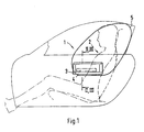
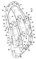
- a side impact protection device 1 for an occupant 2 comprises a housing 3, a gas generator 4 and a folded airbag 5, wherein the housing 3, the gas generator 4 connected to the housing 3 and the gas bag 5 form prefabricated built-in module 6, the at its side mounting part 7 in position is held.
- the built-in module 6 is attached to a door inner panel and the upstream fairing part 8 is formed by a door inner lining.
- installation module 6 could also be attached to a fixed side wall be, wherein the cowling 8 then by an upstream side panel is formed.
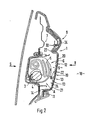
- the cover 10 in the embodiment comprises an outer, on adjacent trim panel 8 fixed frame part 11 and two arranged one above the other, formed integrally with the frame part 11 Flap halves 12, 13.
- the flap halves 12, 13 are at the outer Frame part 11 facing edge except for an upper and a lower Hinge area over a weakening 14 (tear line) to the outer frame part 11 connected.
- the wall thickness is approximately between zero and 0.4 mm, whereas the wall thickness in the hinge areas about 0.8 to 1.2 mm.
- Connecting portion 15 extend both valve halves 12, 13 at a small distance each other (gap 16); at intervals of about 60mm, both flap halves 12, 13 connected by a plurality of narrow upright connecting webs 17.
- Both Flap halves 12, 13 are on the one passenger compartment 18 facing side with a decorative cover 19 provided.
- the cover 19 is made by leather, synthetic leather, formed a film or the like.
- the cover 19 consists of two halves 20, 21, adjacent to the common connection region 15 of both valve halves 12, 13 are connected to each other via an approximately horizontally oriented tear seam 22.
- the tear seam 22 forms a predetermined breaking point during inflation of the airbag 5.
- a one-piece cover 19 which adjacent the common connection region 15 has a predetermined breaking point.
- the Predetermined breaking point can, for example, by a laser tear seam provided on the inside be formed on the reference 19.
- the cover 10 is formed by a one-piece, about 2.5 mm thick injection molded part made of Santoprene. But there may be other suitable ones Materials are used to make the cover 10.
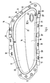
- the flap halves 12, 13 during deployment of the Airbag 5 are on the inside at both flap halves 12, 13 thin-walled Holding plates 23, 24 are provided, each of the outer frame part 11 with the connect adjacent flaps half 12 and 13 in addition to the hinge area.
- Each retaining plate 23, 24 of thin-walled aluminum sheet comprises one each elongated mounting flange 25, 25 ', which on the passenger compartment 18th Abgewandten side of the valve half 12, 13 abuts and with this over several Ultrasonic welding 29 is firmly connected.
- To the mounting flange 25, 25 ' joins a relatively narrow hinge portion 26, 26 ', which with an outer Holding portion 27, 27 'is connected.
- the holding portion 27, 27 ' is located at the rear of the outer frame part 11.
- At least one U-shaped bracket section 28, 28 'of the Holding portion is guided around the outside of the frame part 11 (Hook connection).
- the circumferential frame part 11 of the cover 10 is multiple with the adjacent trim part 8 by ultrasonic welding 30th connected.
- the upper flap portion 12 on both sides of the hinge portion 26th of the holding plate 23 a plurality of upright stiffening ribs (not shown in detail).
- a Plug 37 closable mounting opening 38 is provided through which a Fixing screw 39 for the cover 10 can be used.
- a screw head 40 is supported on an extension 41 of the lower retaining plate 24 and the Fixing screw 39 is in a slide-42 of the housing. 3 screwed in (Fig. 6).
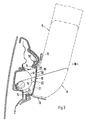
- the two flap halves 12, 13 take on inflated Airbag 5, the positions shown in phantom in Fig. 3 a.
Landscapes
- Engineering & Computer Science (AREA)
- Mechanical Engineering (AREA)
- Air Bags (AREA)
Claims (10)
- Dispositif de protection contre une collision latérale selon la revendication 1, sur une section de paroi verticale d'un caractérisé en ce que pour chaque moitié de clapet (12, 13) est prévue son propre élément d'habillage (20, 21) et en ce que les deux éléments d'habillage (20, 21) sont reliés entre eux par le joint à déchirer (22), et le couvercle (10) comprenant un élément de cadre extérieur (11) périphérique pouvant être fixé à l'élément d'habillage (8) adjacent, une pièce façonnée intérieure entourée par l'élément de cadre extérieur (11) et, sur le côté tourné vers le passager, un revêtement décoratif (19) en deux parties reliées entre elles par un joint à déchirer (22), la pièce façonnée intérieure étant séparée, lors d'un déclenchement du sac gonflable, en deux moitiés de clapet (12, 13) pouvant pivoter, caractérisé en ce que l'élément de cadre extérieur (11) et les deux moitiés de clapet (12, 13) sont réalisés d'un seul tenant, les moitiés de clapet (12, 13) étant reliées à l'élément de cadre extérieur (11) par un affaiblissement (14) périphérique, à l'exception d'une zone de charnière supérieure et d'une zone de charnière inférieure, tandis que dans la zone du joint à déchirer (22), les deux moitiés de clapet (12, 13) s'étendent à faible distance l'une de l'autre et ne sont reliées entre elles que par d'étroites pattes de liaison (17) verticales, disposées par endroits, et en ce que sur la face intérieure des deux moitiés de clapet (12, 13) sont prévues des tôles de maintien (23, 24) à paroi mince qui relient entre eux l'élément de cadre (11) situé à l'extérieur et la moitié de clapet (12, 13) adjacente, chaque tôle de maintien passant, par au moins une section d'étrier (28, 28'), autour du côté extérieur de l'élément de cadre (11).
- Dispositif de protection contre une collision latérale selon la revendication 1, caractérisé en ce que des limiteurs d'ouverture (35) sous la forme de pattes verticales sont disposés par endroits entre l'élément de cadre extérieur (11) et la moitié de clapet (12, 13) adjacente - face à la zone de liaison (15) commune -.
- Dispositif de protection contre une collision latérale selon la revendication 1, caractérisé en ce que pour chaque moitié de clapet (12, 13) est prévue son propre élément d'habillage (20, 21) et en ce que les deux éléments d'habillage (20, 21) sont reliés entre eux par le joint à déchirer (22).
- Dispositif de protection contre une collision latérale selon la revendication 1, caractérisé en ce qu'il est prévu un revêtement (19) en une partie pour les deux moitiés de clapet (12, 13), lequel présente dans la zone de liaison (15) commune un joint à déchirer (22) réalisé au moyen d'un laser.
- Dispositif de protection contre une collision latérale selon la revendication 1, caractérisé en ce que chaque tôle de maintien (23, 24) est reliée à la moitié de clapet (12, 13) adjacente par une ou plusieurs soudures aux ultrasons (29).
- Dispositif de protection contre une collision latérale selon une ou plusieurs des revendications précédentes, caractérisé en ce que chaque tôle de maintien (23, 24) comporte une bride de fixation (25, 25') allongée reliée à la moitié de clapet (12, 13), laquelle bride est reliée par une section de charnière (26, 26') relativement étroite à une section de maintien extérieure (27, 27'), et en ce que sur la section de maintien extérieure (27, 27') sont prévues par endroits les sections d'étrier (28, 28') en U.
- Dispositif de protection contre une collision latérale selon une ou plusieurs des revendications précédentes, caractérisé en ce qu'il est prévu sur une moitié de clapet (13) une ouverture de montage (38) pouvant être fermée par un bouchon (37) inséré, à travers laquelle on peut insérer une vis de fixation (39) pour fixer la tôle de maintien (24) située derrière, sur un boítier (3) de l'airbag.
- Dispositif de protection contre une collision latérale selon une ou plusieurs des revendications précédentes, caractérisé en ce que l'élément de cadre (11) du couvercle (10) et la section de maintien extérieure (27, 27') des deux tôles de maintien (23, 24) peuvent être fixés par endroits par soudage aux ultrasons (30), sur l'élément d'habillage (8) adjacent.
- Dispositif de protection contre une collision latérale selon une ou plusieurs des revendications précédentes, caractérisé en ce que sur la moitié de clapet supérieure (12) sont disposées, des deux côtés de la section de charnière (26) de la tôle de maintien (23), plusieurs nervures de renfort (36) s'étendant verticalement.
- Dispositif de protection contre une collision latérale selon une ou plusieurs des revendications précédentes, caractérisé en ce que le couvercle (10) est formé par une pièce moulée par injection d'un seul tenant en Santoprene.
Applications Claiming Priority (2)
| Application Number | Priority Date | Filing Date | Title |
|---|---|---|---|
| DE19720585 | 1997-05-16 | ||
| DE19720585A DE19720585A1 (de) | 1997-05-16 | 1997-05-16 | Seitenaufprallschutzeinrichtung für einen Insassen eines Fahrzeuges |
Publications (3)
| Publication Number | Publication Date |
|---|---|
| EP0878362A2 EP0878362A2 (fr) | 1998-11-18 |
| EP0878362A3 EP0878362A3 (fr) | 2002-01-23 |
| EP0878362B1 true EP0878362B1 (fr) | 2005-10-12 |
Family
ID=7829670
Family Applications (1)
| Application Number | Title | Priority Date | Filing Date |
|---|---|---|---|
| EP98106957A Expired - Lifetime EP0878362B1 (fr) | 1997-05-16 | 1998-04-16 | Dispositif de protection en cas de choc latéral pour l'occupant d'un véhicule |
Country Status (5)
| Country | Link |
|---|---|
| US (1) | US6086091A (fr) |
| EP (1) | EP0878362B1 (fr) |
| JP (1) | JPH10324214A (fr) |
| KR (1) | KR19980087097A (fr) |
| DE (2) | DE19720585A1 (fr) |
Families Citing this family (24)
| Publication number | Priority date | Publication date | Assignee | Title |
|---|---|---|---|---|
| US6612610B1 (en) * | 1998-09-18 | 2003-09-02 | Honda Giken Kogyo Kabushiki Kaisha | Air bag device |
| DE29915820U1 (de) * | 1999-09-08 | 2000-01-13 | TRW Occupant Restraint Systems GmbH & Co. KG, 73553 Alfdorf | Seitenaufprall-Schutzeinrichtung |
| DE10024293B4 (de) * | 2000-05-17 | 2013-06-13 | TAKATA Aktiengesellschaft | Luftsackanordnung |
| US6371514B1 (en) * | 2000-05-26 | 2002-04-16 | Trw Vehicle Safety Systems Inc. | Air bag module mounted in vehicle door |
| JP3913999B2 (ja) * | 2001-03-02 | 2007-05-09 | カルソニックカンセイ株式会社 | 車両用エアバッグ装置 |
| DE10135614A1 (de) * | 2001-07-21 | 2003-02-13 | Findlay Ind Deutschland Gmbh | Türverkleidung mit Seitenairbag-Modul eines Personenkraftwagens |
| DE10155356B4 (de) * | 2001-11-02 | 2008-04-03 | Brose Fahrzeugteile Gmbh & Co. Kommanditgesellschaft, Coburg | Kraftfahrzeugtür |
| DE60302804T2 (de) * | 2002-01-11 | 2006-07-20 | Toyoda Gosei Co., Ltd. | Knieschutz-Airbagvorrichtung |
| US20030168836A1 (en) | 2002-03-11 | 2003-09-11 | Eiji Sato | Side airbag apparatus |
| DE10220051B4 (de) * | 2002-05-04 | 2016-12-15 | Volkswagen Ag | Sicherheitsvorrichtung an einer Türbrüstung einer Fahrzeugtür |
| DE10304198A1 (de) * | 2003-01-29 | 2004-08-26 | Sai Automotive Sal Gmbh | Innenverkleidungsteil |
| US7144032B2 (en) * | 2003-09-09 | 2006-12-05 | Autoliv Asp, Inc. | Expandable pelvic side airbag |
| US7413215B2 (en) * | 2003-09-17 | 2008-08-19 | Delphi Technologies, Inc. | Method and apparatus for providing an inflatable cushion for use with a vehicle door |
| EP1559622B1 (fr) * | 2004-01-27 | 2013-05-22 | Takata Corporation | Dispositif de protection d'un passager de véhicule |
| EP1577172B1 (fr) * | 2004-03-17 | 2012-11-14 | Takata AG | Dispositif d'airbag |
| DE102004013036B4 (de) * | 2004-03-26 | 2011-04-14 | Faurecia Innenraum Systeme Gmbh | Vorrichtung zum Kopf- und/oder Schulteraufprallschutz bei einer Seitenkollision und/oder einem Überschlag |
| US20060012155A1 (en) * | 2004-07-01 | 2006-01-19 | Ford Global Technologies, Llc | Vehicle side airbag apparatus and seat containing same |
| DE102005024268A1 (de) * | 2005-05-20 | 2006-11-23 | Polytec Interior Gmbh | Sicherheitseinrichtung |
| US7581751B2 (en) * | 2005-08-05 | 2009-09-01 | Honda Motor Co., Ltd. | Air bag device |
| JP4481254B2 (ja) * | 2006-02-02 | 2010-06-16 | 本田技研工業株式会社 | エアバッグ装置 |
| JP4793104B2 (ja) * | 2006-06-01 | 2011-10-12 | 豊田合成株式会社 | サイドエアバッグ装置 |
| JP4940772B2 (ja) * | 2006-06-13 | 2012-05-30 | 日産自動車株式会社 | エアバッグ装置 |
| DE102009041516A1 (de) * | 2009-09-14 | 2011-03-24 | Dr. Ing. H.C. F. Porsche Aktiengesellschaft | Fahrzeugtür |
| DE102009060380A1 (de) * | 2009-12-24 | 2011-06-30 | Dr. Ing. h.c. F. Porsche Aktiengesellschaft, 70435 | Tür für ein Kraftfahrzeug |
Family Cites Families (26)
| Publication number | Priority date | Publication date | Assignee | Title |
|---|---|---|---|---|
| DE3315535A1 (de) * | 1983-04-29 | 1984-03-22 | Daimler-Benz Ag, 7000 Stuttgart | Abdeckung fuer ein aufblasbares gaskissen |
| US4989896A (en) * | 1988-10-17 | 1991-02-05 | Tip Engineering Group, Inc. | Double door closure for an air bag deployment opening |
| US5062664A (en) * | 1989-05-11 | 1991-11-05 | Allied-Signal Inc. | Air bag assembly |
| JP2759819B2 (ja) * | 1989-05-24 | 1998-05-28 | マツダ株式会社 | 自動車のエアバッグ装置 |
| US5744776A (en) * | 1989-07-14 | 1998-04-28 | Tip Engineering Group, Inc. | Apparatus and for laser preweakening an automotive trim cover for an air bag deployment opening |
| DE4101286A1 (de) * | 1991-01-17 | 1992-07-23 | Trw Repa Gmbh | Aufblasbarer gassack fuer rueckhaltesysteme in fahrzeugen |
| US5224732A (en) * | 1991-07-16 | 1993-07-06 | Toyota Motor Co Ltd | Inflatable restraint system for side impact crash protection |
| JP3265510B2 (ja) * | 1992-04-10 | 2002-03-11 | 豊田合成株式会社 | エアバッグ装置 |
| DE4214662C2 (de) * | 1992-05-02 | 2001-10-18 | Porsche Ag | Aufprallschutzeinrichtung für einen Insassen eines Kraftfahrzeuges |
| US5275432A (en) * | 1992-10-30 | 1994-01-04 | Alliedsignal Inc. | Air bag deployment door with snap fit |
| JPH06227348A (ja) * | 1993-02-05 | 1994-08-16 | Toyota Motor Corp | サイドエアバッグ装置 |
| DE4311241C1 (de) * | 1993-04-06 | 1994-04-28 | Daimler Benz Ag | Abdeckplatte für einen in einem Gehäuse eingefalteten Gassack |
| JPH0796811A (ja) * | 1993-09-28 | 1995-04-11 | Kansei Corp | 樹脂製品及びエアバッグ装置用リッド |
| DE4410889C2 (de) * | 1994-03-29 | 1996-03-28 | Opel Adam Ag | Airbagabdeckung |
| DE9408908U1 (de) * | 1994-05-31 | 1994-11-17 | Trw Repa Gmbh | Gassack-Schutzvorrichtung |
| DE4430412C1 (de) * | 1994-08-26 | 1995-10-12 | Porsche Ag | Seitenaufprallschutzeinrichtung für einen Insassen eines Fahrzeuges |
| GB2293355B (en) * | 1994-09-08 | 1997-12-17 | Alliedsignal Deutschland Gmbh | Inflatable safety restraint for vehicle occupant protection |
| DE4437773C1 (de) * | 1994-10-24 | 1995-10-26 | Daimler Benz Ag | Instrumententafel mit einem integrierten, aufklappbaren Gassackdeckel |
| DE4443027A1 (de) * | 1994-12-02 | 1996-06-05 | Trw Repa Gmbh | Seitenaufprall-Gassack |
| DE19505214C2 (de) * | 1995-02-16 | 2000-05-04 | Johnson Contr Interiors Gmbh | Innenverkleidungsteil für eine Seitentür eines Personenkraftwagens |
| DE19511511A1 (de) | 1995-03-29 | 1996-02-22 | Daimler Benz Ag | Gassack in einem Kraftwagen |
| US5662351A (en) * | 1995-08-21 | 1997-09-02 | Trw Vehicle Safety Systems Inc. | Air bag deployment door |
| DE19535430A1 (de) * | 1995-09-23 | 1997-03-27 | Vaw Ver Aluminium Werke Ag | Airbagprofil |
| DE29517372U1 (de) * | 1995-11-02 | 1996-02-01 | Trw Repa Gmbh | Gassack-Seitenaufprall-Schutzeinrichtung |
| DE29608055U1 (de) * | 1996-04-24 | 1996-07-18 | Daimler Benz Ag | Gassack, insbesondere für ein Seitenairbagmodul |
| US5906390A (en) * | 1997-05-19 | 1999-05-25 | Trw Vehicle Safety Systems Inc. | Vehicle occupant protection apparatus |
-
1997
- 1997-05-16 DE DE19720585A patent/DE19720585A1/de not_active Ceased
-
1998
- 1998-04-16 DE DE59813097T patent/DE59813097D1/de not_active Expired - Fee Related
- 1998-04-16 EP EP98106957A patent/EP0878362B1/fr not_active Expired - Lifetime
- 1998-05-13 JP JP10130113A patent/JPH10324214A/ja active Pending
- 1998-05-15 KR KR1019980017548A patent/KR19980087097A/ko not_active Withdrawn
- 1998-05-15 US US09/079,389 patent/US6086091A/en not_active Expired - Fee Related
Also Published As
| Publication number | Publication date |
|---|---|
| KR19980087097A (ko) | 1998-12-05 |
| EP0878362A2 (fr) | 1998-11-18 |
| DE19720585A1 (de) | 1998-11-19 |
| DE59813097D1 (de) | 2005-11-17 |
| US6086091A (en) | 2000-07-11 |
| EP0878362A3 (fr) | 2002-01-23 |
| JPH10324214A (ja) | 1998-12-08 |
Similar Documents
| Publication | Publication Date | Title |
|---|---|---|
| EP0878362B1 (fr) | Dispositif de protection en cas de choc latéral pour l'occupant d'un véhicule | |
| DE69903797T2 (de) | Nahtlose airbag-abdeckung für ein armaturenbrett | |
| EP0235383B1 (fr) | Dispositif de protection contre les chocs pour les occupants d'un véhicule automobile | |
| DE69601001T2 (de) | Deckel für eine Wandöffnung in einem Luftsack-Aufprallschutz-System | |
| DE3707370C2 (fr) | ||
| DE69214543T2 (de) | Aufprallschutzvorrichtung | |
| DE10000768B4 (de) | Aufblasbare Seitenvorhanganordnung für ein Fahrzeug | |
| DE68919946T2 (de) | Verschluss für eine Luftsack-Entfaltungsöffnung. | |
| DE69306331T2 (de) | Air-Bag-Abdeckung für Hochleistungs-Gasgenerator und Scharnier dafür | |
| EP0878358B1 (fr) | Dispositif de protection en cas d'accident pour un occupant de véhicule automobile | |
| DE69611475T2 (de) | Airbag Abdeckungsanordnung | |
| DE102004051877A1 (de) | Instrumententafel mit modularer Airbagklappenbaugruppe | |
| DE3918281C2 (de) | Aufprallschutzvorrichtung für einen Kraftfahrzeuginsassen, insbesondere für einen Beifahrer | |
| DE19640434A1 (de) | Einsatztüranordnung | |
| DE69204217T2 (de) | Verbesserungen von Luftsack-Aufprall-Schutzsystemen. | |
| DE4229379A1 (de) | Abdeckung einer Aufprallschutzvorrichtung für Fahrzeuginsassen | |
| DE19829755B4 (de) | Airbagvorrichtung für ein Kraftfahrzeug | |
| DE69512178T2 (de) | Nahtlose Abdeckung für ein Airbag-Modul | |
| WO2001042060A1 (fr) | Systeme a airbag integre dans une partie de revetement interieur pour vehicules automobiles | |
| EP0510738B1 (fr) | Dispositif de protection à coussin gonflable | |
| DE19750945A1 (de) | Seitenaufprallschutzmodul zur Montage an einem Sitz eines Kraftfahrzeugs | |
| EP0686531A1 (fr) | Dispositif de protection à sac gonflable contre les collisions | |
| EP1445156A1 (fr) | Dispositif de protection contre le choc latéral pour un occupant de véhicule | |
| DE19653512A1 (de) | Airbagabdeckung in einem Kraftfahrzeug | |
| DE19604014C2 (de) | Vorrichtung zum Schutz von Insassen eines KFZ |
Legal Events
| Date | Code | Title | Description |
|---|---|---|---|
| PUAI | Public reference made under article 153(3) epc to a published international application that has entered the european phase |
Free format text: ORIGINAL CODE: 0009012 |
|
| AK | Designated contracting states |
Kind code of ref document: A2 Designated state(s): AT BE CH CY DE DK ES FI FR GB GR IE IT LI LU MC NL PT SE Kind code of ref document: A2 Designated state(s): DE FR GB IT |
|
| AX | Request for extension of the european patent |
Free format text: AL;LT;LV;MK;RO;SI |
|
| PUAL | Search report despatched |
Free format text: ORIGINAL CODE: 0009013 |
|
| AK | Designated contracting states |
Kind code of ref document: A3 Designated state(s): AT BE CH CY DE DK ES FI FR GB GR IE IT LI LU MC NL PT SE |
|
| AX | Request for extension of the european patent |
Free format text: AL;LT;LV;MK;RO;SI |
|
| 17P | Request for examination filed |
Effective date: 20020723 |
|
| AKX | Designation fees paid |
Free format text: DE FR GB IT |
|
| 17Q | First examination report despatched |
Effective date: 20040830 |
|
| GRAP | Despatch of communication of intention to grant a patent |
Free format text: ORIGINAL CODE: EPIDOSNIGR1 |
|
| GRAS | Grant fee paid |
Free format text: ORIGINAL CODE: EPIDOSNIGR3 |
|
| GRAA | (expected) grant |
Free format text: ORIGINAL CODE: 0009210 |
|
| AK | Designated contracting states |
Kind code of ref document: B1 Designated state(s): DE FR GB IT |
|
| REG | Reference to a national code |
Ref country code: GB Ref legal event code: FG4D Free format text: NOT ENGLISH |
|
| REF | Corresponds to: |
Ref document number: 59813097 Country of ref document: DE Date of ref document: 20051117 Kind code of ref document: P |
|
| GBT | Gb: translation of ep patent filed (gb section 77(6)(a)/1977) |
Effective date: 20060109 |
|
| ET | Fr: translation filed | ||
| PLBE | No opposition filed within time limit |
Free format text: ORIGINAL CODE: 0009261 |
|
| STAA | Information on the status of an ep patent application or granted ep patent |
Free format text: STATUS: NO OPPOSITION FILED WITHIN TIME LIMIT |
|
| 26N | No opposition filed |
Effective date: 20060713 |
|
| PGFP | Annual fee paid to national office [announced via postgrant information from national office to epo] |
Ref country code: DE Payment date: 20070405 Year of fee payment: 10 |
|
| PGFP | Annual fee paid to national office [announced via postgrant information from national office to epo] |
Ref country code: GB Payment date: 20070426 Year of fee payment: 10 |
|
| PGFP | Annual fee paid to national office [announced via postgrant information from national office to epo] |
Ref country code: IT Payment date: 20070614 Year of fee payment: 10 |
|
| PGFP | Annual fee paid to national office [announced via postgrant information from national office to epo] |
Ref country code: FR Payment date: 20070416 Year of fee payment: 10 |
|
| GBPC | Gb: european patent ceased through non-payment of renewal fee |
Effective date: 20080416 |
|
| PG25 | Lapsed in a contracting state [announced via postgrant information from national office to epo] |
Ref country code: DE Free format text: LAPSE BECAUSE OF NON-PAYMENT OF DUE FEES Effective date: 20081101 |
|
| REG | Reference to a national code |
Ref country code: FR Ref legal event code: ST Effective date: 20081231 |
|
| PG25 | Lapsed in a contracting state [announced via postgrant information from national office to epo] |
Ref country code: FR Free format text: LAPSE BECAUSE OF NON-PAYMENT OF DUE FEES Effective date: 20080430 |
|
| PG25 | Lapsed in a contracting state [announced via postgrant information from national office to epo] |
Ref country code: GB Free format text: LAPSE BECAUSE OF NON-PAYMENT OF DUE FEES Effective date: 20080416 |
|
| PG25 | Lapsed in a contracting state [announced via postgrant information from national office to epo] |
Ref country code: IT Free format text: LAPSE BECAUSE OF NON-PAYMENT OF DUE FEES Effective date: 20080416 |