EP0878390A2 - Structure de cloison - Google Patents
Structure de cloison Download PDFInfo
- Publication number
- EP0878390A2 EP0878390A2 EP98303703A EP98303703A EP0878390A2 EP 0878390 A2 EP0878390 A2 EP 0878390A2 EP 98303703 A EP98303703 A EP 98303703A EP 98303703 A EP98303703 A EP 98303703A EP 0878390 A2 EP0878390 A2 EP 0878390A2
- Authority
- EP
- European Patent Office
- Prior art keywords
- wall structure
- vertical
- structure according
- wall
- corrugated plate
- Prior art date
- Legal status (The legal status is an assumption and is not a legal conclusion. Google has not performed a legal analysis and makes no representation as to the accuracy of the status listed.)
- Granted
Links
Images

Classifications
-
- B—PERFORMING OPERATIONS; TRANSPORTING
- B63—SHIPS OR OTHER WATERBORNE VESSELS; RELATED EQUIPMENT
- B63B—SHIPS OR OTHER WATERBORNE VESSELS; EQUIPMENT FOR SHIPPING
- B63B29/00—Accommodation for crew or passengers not otherwise provided for
- B63B29/02—Cabins or other living spaces; Construction or arrangement thereof
-
- B—PERFORMING OPERATIONS; TRANSPORTING
- B63—SHIPS OR OTHER WATERBORNE VESSELS; RELATED EQUIPMENT
- B63B—SHIPS OR OTHER WATERBORNE VESSELS; EQUIPMENT FOR SHIPPING
- B63B3/00—Hulls characterised by their structure or component parts
- B63B3/14—Hull parts
- B63B3/68—Panellings; Linings, e.g. for insulating purposes
-
- E—FIXED CONSTRUCTIONS
- E04—BUILDING
- E04B—GENERAL BUILDING CONSTRUCTIONS; WALLS, e.g. PARTITIONS; ROOFS; FLOORS; CEILINGS; INSULATION OR OTHER PROTECTION OF BUILDINGS
- E04B1/00—Constructions in general; Structures which are not restricted either to walls, e.g. partitions, or floors or ceilings or roofs
- E04B1/18—Structures comprising elongated load-supporting parts, e.g. columns, girders, skeletons
- E04B1/24—Structures comprising elongated load-supporting parts, e.g. columns, girders, skeletons the supporting parts consisting of metal
-
- E—FIXED CONSTRUCTIONS
- E04—BUILDING
- E04B—GENERAL BUILDING CONSTRUCTIONS; WALLS, e.g. PARTITIONS; ROOFS; FLOORS; CEILINGS; INSULATION OR OTHER PROTECTION OF BUILDINGS
- E04B1/00—Constructions in general; Structures which are not restricted either to walls, e.g. partitions, or floors or ceilings or roofs
- E04B1/62—Insulation or other protection; Elements or use of specified material therefor
- E04B1/74—Heat, sound or noise insulation, absorption, or reflection; Other building methods affording favourable thermal or acoustical conditions, e.g. accumulating of heat within walls
- E04B1/88—Insulating elements for both heat and sound
-
- E—FIXED CONSTRUCTIONS
- E04—BUILDING
- E04B—GENERAL BUILDING CONSTRUCTIONS; WALLS, e.g. PARTITIONS; ROOFS; FLOORS; CEILINGS; INSULATION OR OTHER PROTECTION OF BUILDINGS
- E04B7/00—Roofs; Roof construction with regard to insulation
- E04B7/20—Roofs consisting of self-supporting slabs, e.g. able to be loaded
- E04B7/22—Roofs consisting of self-supporting slabs, e.g. able to be loaded the slabs having insulating properties, e.g. laminated with layers of insulating material
-
- E—FIXED CONSTRUCTIONS
- E04—BUILDING
- E04C—STRUCTURAL ELEMENTS; BUILDING MATERIALS
- E04C2/00—Building elements of relatively thin form for the construction of parts of buildings, e.g. sheet materials, slabs, or panels
- E04C2/02—Building elements of relatively thin form for the construction of parts of buildings, e.g. sheet materials, slabs, or panels characterised by specified materials
- E04C2/26—Building elements of relatively thin form for the construction of parts of buildings, e.g. sheet materials, slabs, or panels characterised by specified materials composed of materials covered by two or more of groups E04C2/04, E04C2/08, E04C2/10 or of materials covered by one of these groups with a material not specified in one of the groups
- E04C2/284—Building elements of relatively thin form for the construction of parts of buildings, e.g. sheet materials, slabs, or panels characterised by specified materials composed of materials covered by two or more of groups E04C2/04, E04C2/08, E04C2/10 or of materials covered by one of these groups with a material not specified in one of the groups at least one of the materials being insulating
- E04C2/292—Building elements of relatively thin form for the construction of parts of buildings, e.g. sheet materials, slabs, or panels characterised by specified materials composed of materials covered by two or more of groups E04C2/04, E04C2/08, E04C2/10 or of materials covered by one of these groups with a material not specified in one of the groups at least one of the materials being insulating composed of insulating material and sheet metal
-
- E—FIXED CONSTRUCTIONS
- E04—BUILDING
- E04C—STRUCTURAL ELEMENTS; BUILDING MATERIALS
- E04C2/00—Building elements of relatively thin form for the construction of parts of buildings, e.g. sheet materials, slabs, or panels
- E04C2/30—Building elements of relatively thin form for the construction of parts of buildings, e.g. sheet materials, slabs, or panels characterised by the shape or structure
- E04C2/32—Building elements of relatively thin form for the construction of parts of buildings, e.g. sheet materials, slabs, or panels characterised by the shape or structure formed of corrugated or otherwise indented sheet-like material; composed of such layers with or without layers of flat sheet-like material
- E04C2/322—Building elements of relatively thin form for the construction of parts of buildings, e.g. sheet materials, slabs, or panels characterised by the shape or structure formed of corrugated or otherwise indented sheet-like material; composed of such layers with or without layers of flat sheet-like material with parallel corrugations
-
- B—PERFORMING OPERATIONS; TRANSPORTING
- B63—SHIPS OR OTHER WATERBORNE VESSELS; RELATED EQUIPMENT
- B63B—SHIPS OR OTHER WATERBORNE VESSELS; EQUIPMENT FOR SHIPPING
- B63B2221/00—Methods and means for joining members or elements
- B63B2221/10—Methods and means for joining members or elements using adhesives
-
- B—PERFORMING OPERATIONS; TRANSPORTING
- B63—SHIPS OR OTHER WATERBORNE VESSELS; RELATED EQUIPMENT
- B63B—SHIPS OR OTHER WATERBORNE VESSELS; EQUIPMENT FOR SHIPPING
- B63B2231/00—Material used for some parts or elements, or for particular purposes
- B63B2231/02—Metallic materials
- B63B2231/04—Irons, steels or ferrous alloys
-
- E—FIXED CONSTRUCTIONS
- E04—BUILDING
- E04B—GENERAL BUILDING CONSTRUCTIONS; WALLS, e.g. PARTITIONS; ROOFS; FLOORS; CEILINGS; INSULATION OR OTHER PROTECTION OF BUILDINGS
- E04B2/00—Walls, e.g. partitions, for buildings; Wall construction with regard to insulation; Connections specially adapted to walls
- E04B2/72—Non-load-bearing walls of elements of relatively thin form with respect to the thickness of the wall
Definitions
- This invention relates to a wall structure according to the preamble of claim 1 and to a wall element for such a wall structure.
- An object of the present invention is to provide a wall structure which is thin and relatively lightweight, is sufficiently stiff vertically as well as horizontally and has good fire-resisting and sound-insulating properties.
- the fire-proof properties of the wall structure should meet a high standard and the sound-insulation should be good, in particular be within the frequency range 100 to 200 Hz.
- a wall structure as claimed in the ensuing claim 1.
- the corrugations of the corrugated plate extend at least substantially horizontally to provide the horizontal stiffening of the wall structure.
- the or each corrugated plate is attached to the vertical stiffening element(s) substantially only by virtue of being adhesively bonded to the surface plate means.
- the or each corrugated plate preferably has no direct connection with any of the vertical stiffening elements.
- the surface plate means are conveniently adhesively bonded to the vertical stiffening elements, and this adhesive bonding should preferably be secured by means of screws or the like for maintaining the fire-resisting properties of the structure in the event of the glue being destroyed by the heat of a fire.
- a wall structure including surface plate means rigidly secured to a vertical stiffening element and adhesively bonded to a horizontally stiffening corrugated plate can be made sufficiently stiff with a wall thickness between the vertical stiffening elements of only from 5 to 10 mm for many applications.
- Such a wall structure can be provided with insulating means such as a glass or rock wool layer advantageously having a thickness of about 10 mm, and typically adhesively bonded or otherwise attached to the corrugated plate.
- the use of two or more superimposed insulating layers improves both the fire-resisting properties and the sound-insulating properties of the wall structure.
- a wall structure of this kind has proved to be highly advantageous as a wall structure erectable at the building site or for use in prefabricated room units such as passenger cabins.
- the invention is used as a relatively thin wall. If a very strong wall with particularly good fire-resisting-properties is required, the total thickness of the corrugated plate may be up to 20 mm. Generally, however, it is not warranted to use a corrugated plate thicker than 15 mm. Normally, the height of the corrugations is no more than 8 mm, preferably no more than 6 mm. This gives the wall structure a quite satisfactory stiffness if the surface plate means and corrugated panel are made of steel. At the same time good sound-insulation and good fire-resistance is obtained. A fire-proof insulation layer attached to the steel structure also further improves these properties. Rock wool is a reliable insulation material. The fire-resistance of glass wool, although adequate for some applications, is poorer because it melts at a considerably lower temperature than rock wool.
- a single layer soft rock wool mat or a stiffer panel-like rock wool unit is in general sufficient as an insulating layer although two or more superimposed insulating layers may be provided.
- the density of such an insulating layer is advantageously from 100 to 200 kg/m 3 , preferably from 150 to 200 kg/m 3 . Insulation having a higher density as a rule provides better fire insulation than an insulation of lower density.
- the panel-like element has the advantage that it is self-supporting and may therefore be easier to install.
- each ridge of the corrugations glued or bonded to the surface plate means is conveniently formed as a plane or flat surface having a width of at least some millimetres, preferably about 5 mm. This provides an extremely reliable and strong gluing attachment of the corrugated plate.
- the corrugations of the corrugated plate may also be formed with sharp bends giving them a trapezoidal configuration.
- the portions between ridge portions on opposite sides of the corrugated plate are generally linear.
- the angle between these linear portions and the surface plate means should not be made too large, because if the angle is too large it is more difficult to bore holes and apply screws through the wall. An angle of from 30° to 45°, preferably from 30° to 40°, is recommended.
- Coated steel is a suitable material for the corrugated plate and the surface plate means.
- coated includes all kinds of coating or covering measures, such as painting, galvanizing, plastic covering etc.
- the surface plate means may be a 0.7 or 0.6 mm thick plate, e.g. a steel plate, having a coating of PVC on its surface facing away from corrugated plate and a paint coating on its surface facing toward the corrugated plate.
- the corrugated plate may be made of a galvanized steel plate having a material thickness of about 0.5 mm.
- the thickness of the surface plate means and the material thickness of the corrugated plate should be selected to obtain sufficient stiffness and fire-resistance. The stiffness is considerably influenced by the distance between the vertical stiffening elements. If a particularly light wall structure is required, aluminium plates may be used as surface plate means and/or corrugated plates, but such a structure is considerably more expensive than a steel structure.
- the vertical stiffening elements may with advantage be made of steel tubes of rectangular cross-section. However, stiffening elements of other profiles of steel or other metals can be used as well. In order to obtain sufficient stiffening, it is of advantage for the dimension of the stiffening elements perpendicular to the wall plane to be considerably greater than the overall thickness of the corrugated plate. With such a construction a space is created between the vertical stiffening elements in which insulating material can easily be placed.
- a wall structure according to the invention can be assembled from wall elements attached to one another side by side and each having a different one of the vertical stiffening elements at one vertical edge.
- the surface plate means is attached, preferably by gluing, to the vertical stiffening element of each wall element and the surface plate means of the adjacent wall element is attached, during assembly, to the same vertical stiffening element, preferably by means of screws, rivets or the like. It is recommended that both vertical edges of the surface plate means are provided with bends coinciding with one side of the vertical stiffening element. These bends may also have a continuation in the form of a second bend more or less parallel to the wall plane. These bends have a stiffening influence on the wall elements and facilitate the joining together of the wall elements.
- the horizonal width of the wall elements in the wall plane may be selected to fit a modular system. If the wall elements are too broad they are difficult to handle. A width of from 80 to 150 cm, preferably from 85 to 100 cm, is recommended.
- the corrugated plates are fitted between a vertical stiffening element along one vertical edge of a wall element and a bent portion of the surface plate means at its remote vertical edge. It is of advantage that the horizontal length of the corrugated plate as close as possible corresponds to the horizontal dimension of the space provided for the corrugated plate. The clearance required for fitting in the corrugated plate is thus kept to a minimum achieving the best sound insulation and the best fire resistance. If the insulating means is in the form of one or more insulating panels, the or each panel may be somewhat over-sized relative to the space provided. Its unloaded horizontal dimension is then somewhat greater than the corresponding dimension of the corrugated plate.
- the insulating means may be adhesively bonded to the corrugated plate(s).
- the fire-resisting properties of the wall structure may be increased by additionally securing the insulating means against the corrugated plate(s) by means of heat-resisting attachment elements, typically screwed or riveted to the vertical stiffening elements.
- heat-resisting attachment elements typically screwed or riveted to the vertical stiffening elements.
- a wall structure in accordance with the invention may be used as an exterior wall of a prefabricated cabin unit for installation in a passenger ship.
- the surface plate means face the interior of the cabin and the corrugated plate (or the insulating means positioned thereagainst) faces a concealed space, such as a clearance between the adjacent cabin units.
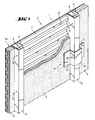
- the wall structure shown in the drawings comprises a surface plate 1, a corrugated plate 2 adhesively bonded to the surface plate 1, an insulation layer 3 and a vertical stiffening element or stiffener 4.
- the surface plate 1 is a 0.7 mm steel plate plated with PVC on its side away from the corrugated plate 2.
- the side of the plate 1 facing the corrugated plate 2 may be painted.
- the corrugated plate 2 is made of a 0.5 mm thinly galvanized steel plate.
- the galvanizing layer should not be too thick since it would impair the fire resistance of the wall structure.
- the corrugations of the plate 2 are generally horizontally orientated and typically have the form shown in Fig. 4.
- the vertical stiffeners are made of substantially rectangular 25 x 25 mm steel tubes.
- the insulation layer 3 conveniently comprises a rock wool mat of 10 mm thickness.
- Figs. 2 and 3 show how two wall elements 5 and 5a are joined together.
- Each wall element has a vertical stiffener 4 at one vertical edge and no vertical stiffener at its opposite vertical edge.
- the surface plate 1 is bent at the vertical edge of the wall element 5 containing the vertical element 4 into two right angle bends, a first bend 6 perpendicular to the plane of the wall and a second bend 7 parallel to the wall plane.
- the vertical stiffener has two side surfaces 4a and 4b to which the surface plate 1 is glued. Between the back surface 4c of the vertical stiffener and the bend 7 of the surface plate there is a gap 8 of some millimetres to facilitate the assembly of the wall elements.
- the adjacent wall element 5a has, at its one vertical edge where there is no vertical stiffener, two right angle bends 6a and 7a.
- the bend 6a is so dimensioned that the bend 7a coincides with the bend 7, when the surface plates 1 of both the wall elements 5 and 5a are aligned.
- the wall elements 5 and 5a have a horizontal width of approximately 100 cm. Their joint is secured by means of several attachment screws (not shown) which are positioned at different heights at the position of the line 9. These screws secure the glued attachment of the surface plate 1 to the vertical stiffener 4.
- Fig. 1 shows how the glued attachment of the corrugated plate 2 and the insulation layer 3 may be additionally secured by, for example, metallic fastening elements 15. Only one such fastening element is shown, but preferably several of these are used at each vertical stiffener 4. It is also possible to increase the vertical size or dimension of these elements so that the elements 15 have more of a strip-like form.
- the elements 15 are used in particular if one or more additional insulation layer is placed over the insulation layer 3.
- the element 15 shown includes a central part 16 extending over the vertical stiffener 4 and the bends of the surface plates 1 and being U-shaped if necessary. At both sides of the central part 16 there is a relatively broad support flange 17 lightly pressing against the insulation layer or layers.
- the central part 16 is, at one or both of its sides, attached to the vertical stiffener 4 by means of one or several screws or rivets 18, if there is sufficient space. If there is not sufficient space the attachment is made at the back side 4c of the vertical stiffener 4.
- Fig. 4 shows a corrugated plate 2, in which the corrugations have been made by bending the plate so that, at both sides of the plate, a number of plane surfaces or flattened ridge portions 12 and 13 are formed.
- the flattened ridge portions lie substantially in one plane and the flattened ridge portions 13 lie substantially in a spaced apart parallel plane.
- Each ridge portion 13 has a width of almost 5 mm and is used for adhesively bonding the corrugated plate 2 to the surface plate 1.
- the insulating layer 3 may be glued to the flattened ridge portions 12.
- the ridge portions 12 and 13 may include small apertures, recesses or other unevennesses, by means of which a larger adhesion area is created for the glue.
- the use of an inorganic glue increases fire safety. However, this is not essential and, for example, polyurethane glues may be used in many cases.
- the total thickness of the corrugated plate 2 is approximately 7 mm.
- the portions 14 of the corrugated plate between the ridge portions 12 and 13 are substantially flat and are at an angle of approximately 40 degrees to the wall plane.
- the corrugated plate 2 has no direct connection with the vertical stiffeners 4.
- the corrugated plate is attached to the vertical stiffeners substantially only by virtue of being adhesively bonded to the surface plate 1.
- the wall structure described above is favourable with respect to sound insulation properties because the lack of a direct connection between the vertical stiffeners and the corrugated plate means that vibrations, including sound, transmitted to the vertical stiffeners from the structure on which they are supported, such as an underlying deck or the like, or to which they may be attached, such as the floor and ceiling of the surrounding structure, are not easily transmitted to the corrugated plate.
- the surface plate is attached to the corrugated plate by adhesive bonding, which is more yielding than metallic contact, e.g. welding, vibrations, including sound, transmitted from the vertical stiffeners to the surface plate are effectively damped. Further, attaching the corrugated plate to the surface plate by adhesive bonding is relatively simple and inexpensive because it does not require skilled labour.
Landscapes
- Engineering & Computer Science (AREA)
- Architecture (AREA)
- Civil Engineering (AREA)
- Structural Engineering (AREA)
- Ocean & Marine Engineering (AREA)
- Chemical & Material Sciences (AREA)
- Combustion & Propulsion (AREA)
- Mechanical Engineering (AREA)
- Physics & Mathematics (AREA)
- Electromagnetism (AREA)
- Acoustics & Sound (AREA)
- Building Environments (AREA)
- Finishing Walls (AREA)
- Glass Compositions (AREA)
- Panels For Use In Building Construction (AREA)
Applications Claiming Priority (2)
| Application Number | Priority Date | Filing Date | Title |
|---|---|---|---|
| FI972025A FI972025A7 (fi) | 1997-05-13 | 1997-05-13 | Seinärakenne |
| FI972025 | 1997-05-13 |
Publications (3)
| Publication Number | Publication Date |
|---|---|
| EP0878390A2 true EP0878390A2 (fr) | 1998-11-18 |
| EP0878390A3 EP0878390A3 (fr) | 1999-08-11 |
| EP0878390B1 EP0878390B1 (fr) | 2003-09-03 |
Family
ID=8548841
Family Applications (1)
| Application Number | Title | Priority Date | Filing Date |
|---|---|---|---|
| EP98303703A Expired - Lifetime EP0878390B1 (fr) | 1997-05-13 | 1998-05-12 | Structure de cloison |
Country Status (10)
| Country | Link |
|---|---|
| US (1) | US6155016A (fr) |
| EP (1) | EP0878390B1 (fr) |
| JP (1) | JPH10317548A (fr) |
| KR (1) | KR100538079B1 (fr) |
| DE (1) | DE69817670T2 (fr) |
| DK (1) | DK0878390T3 (fr) |
| ES (1) | ES2206841T3 (fr) |
| FI (1) | FI972025A7 (fr) |
| HR (1) | HRP980253B1 (fr) |
| NO (1) | NO317856B1 (fr) |
Cited By (5)
| Publication number | Priority date | Publication date | Assignee | Title |
|---|---|---|---|---|
| KR100538079B1 (ko) * | 1997-05-13 | 2006-05-09 | 아께르 핀야즈 오이 | 벽구조 |
| WO2006131692A1 (fr) * | 2005-06-07 | 2006-12-14 | Tba Textiles Limited | Systeme d'isolation de paroi metallique |
| WO2007057513A1 (fr) * | 2005-11-18 | 2007-05-24 | Aker Yards Cabins Oy. | Structure de mur |
| GB2470082A (en) * | 2009-04-03 | 2010-11-10 | Michael Heffron | Fixing device |
| EP3118100A3 (fr) * | 2015-07-14 | 2017-02-22 | Piikkio Works Oy | Structure de paroi |
Families Citing this family (14)
| Publication number | Priority date | Publication date | Assignee | Title |
|---|---|---|---|---|
| ITGE20010013A1 (it) * | 2001-02-09 | 2002-08-09 | Impresa Marinoni S R L | Strutture adatte all'allestimento di locali umidi e relativo procedimento di montaggio. |
| NL1023780C2 (nl) * | 2003-06-30 | 2005-01-03 | Alcoa Nederland Bv | Plint voor een scheidingswand. |
| FI124620B (fi) * | 2005-01-28 | 2014-11-14 | Neapo Oy | Huonetilajärjestely, laiva, rakennus ja menetelmä huonetilajärjestelyn rakentamiseksi |
| US20060254202A1 (en) * | 2005-05-13 | 2006-11-16 | Dan Villanella | Lightweight shielded panel system including acoustical shielding |
| FR2889616B1 (fr) * | 2005-08-02 | 2008-05-30 | Hutchinson Sa | Panneau acoustique du type a lame d'air |
| US20090151278A1 (en) * | 2007-12-18 | 2009-06-18 | Cornerstone Specialty Wood Products, Llc | Flooring system and method for installing involving a corrugated member and a panel flooring member |
| US20100233503A1 (en) * | 2009-03-13 | 2010-09-16 | Zachman Joseph M | Panel for a storage container |
| KR20140003392A (ko) * | 2010-08-12 | 2014-01-09 | 리빙 쿼터 테크놀로지, 인코포레이티드 | 알루미늄 수용 모듈 및 알루미늄 수용 모듈 구성 방법 |
| WO2012024814A1 (fr) | 2010-08-24 | 2012-03-01 | Empire Technology Development Llc | Systèmes à structures de colonnes denses en béton armé |
| US8844223B2 (en) * | 2010-08-24 | 2014-09-30 | Empire Technology Development Llc | Prefabricated wall panels |
| KR101664880B1 (ko) * | 2014-12-08 | 2016-10-11 | 현대오트론 주식회사 | 듀얼 클러치 변속기의 제어 방법 |
| KR101824077B1 (ko) * | 2015-07-17 | 2018-01-31 | 삼성중공업 주식회사 | 거주구 방화 구조 및 거주구 모듈 |
| KR101840649B1 (ko) * | 2017-11-20 | 2018-03-21 | 알렌 주식회사 | 해상 발전플랫폼의 부유시스템 |
| CN115387499B (zh) * | 2022-09-05 | 2024-01-16 | 苏州科技大学 | 一种防屈曲波形缩口钢板组合耗能构件 |
Family Cites Families (14)
| Publication number | Priority date | Publication date | Assignee | Title |
|---|---|---|---|---|
| DE2418009A1 (de) * | 1973-04-16 | 1974-10-31 | Pjk Projects Ltd | Vorgefertigte paneeltafel zur herstellung von wandpaneelen |
| JPS5829682Y2 (ja) * | 1979-04-15 | 1983-06-29 | 松下電工株式会社 | 建築用板 |
| JPS56151425U (fr) * | 1980-04-15 | 1981-11-13 | ||
| FR2552017A1 (fr) * | 1983-09-19 | 1985-03-22 | Leclerc Thierry | Panneau composite de haute resistance |
| US4736566A (en) * | 1984-01-17 | 1988-04-12 | Krotsch Harold V | Modular fabrication panel system |
| FI75127C (fi) * | 1985-11-28 | 1989-08-28 | Waertsilae Oy Ab | Rumsenhet foer sjoeanordning. |
| CA1283557C (fr) * | 1986-01-31 | 1991-04-30 | Leonid Slonimsky | Panneau pour coffrage de betonnage, et son raccord |
| DE3903511A1 (de) * | 1989-02-06 | 1990-08-09 | Rheinhold & Mahla Gmbh | Ebenes bekleidungselement |
| JP2552017Y2 (ja) * | 1992-07-02 | 1997-10-27 | 株式会社トヨバックス | 2段穴加工用ドリル |
| IT1268968B1 (it) * | 1994-05-23 | 1997-03-18 | Ct Per Gli Studi Di Tecnica Na | Struttura di pannello per la realizzazione di pareti e locali qualicabine e simili in costruzioni navali |
| DE4426743A1 (de) * | 1994-07-28 | 1996-02-01 | Hoechst Ag | Zentrierbüchse |
| JPH0842029A (ja) * | 1995-07-14 | 1996-02-13 | Sanuki Kenko:Kk | 板材装着用支柱及び該支柱を使用した板材装着方法 |
| US5706614A (en) * | 1996-10-16 | 1998-01-13 | Wiley, Jr.; James G. | Modular building having a steel shipping container core |
| FI972025A7 (fi) * | 1997-05-13 | 1998-11-14 | Kvaerner Masa Yards Oy | Seinärakenne |
-
1997
- 1997-05-13 FI FI972025A patent/FI972025A7/fi unknown
-
1998
- 1998-05-12 DK DK98303703T patent/DK0878390T3/da active
- 1998-05-12 ES ES98303703T patent/ES2206841T3/es not_active Expired - Lifetime
- 1998-05-12 US US09/076,526 patent/US6155016A/en not_active Expired - Lifetime
- 1998-05-12 DE DE69817670T patent/DE69817670T2/de not_active Expired - Lifetime
- 1998-05-12 NO NO19982159A patent/NO317856B1/no not_active IP Right Cessation
- 1998-05-12 HR HR972025 patent/HRP980253B1/xx not_active IP Right Cessation
- 1998-05-12 EP EP98303703A patent/EP0878390B1/fr not_active Expired - Lifetime
- 1998-05-13 KR KR1019980017150A patent/KR100538079B1/ko not_active Expired - Lifetime
- 1998-05-13 JP JP10130035A patent/JPH10317548A/ja not_active Ceased
Cited By (7)
| Publication number | Priority date | Publication date | Assignee | Title |
|---|---|---|---|---|
| KR100538079B1 (ko) * | 1997-05-13 | 2006-05-09 | 아께르 핀야즈 오이 | 벽구조 |
| WO2006131692A1 (fr) * | 2005-06-07 | 2006-12-14 | Tba Textiles Limited | Systeme d'isolation de paroi metallique |
| WO2007057513A1 (fr) * | 2005-11-18 | 2007-05-24 | Aker Yards Cabins Oy. | Structure de mur |
| CN101310083B (zh) * | 2005-11-18 | 2010-09-08 | 艾克亚兹船舱有限公司 | 壁结构 |
| GB2470082A (en) * | 2009-04-03 | 2010-11-10 | Michael Heffron | Fixing device |
| EP3118100A3 (fr) * | 2015-07-14 | 2017-02-22 | Piikkio Works Oy | Structure de paroi |
| CN106476982A (zh) * | 2015-07-14 | 2017-03-08 | 皮基厄工厂有限公司 | 壁结构 |
Also Published As
| Publication number | Publication date |
|---|---|
| KR19980087005A (ko) | 1998-12-05 |
| HRP980253B1 (en) | 2004-12-31 |
| NO317856B1 (no) | 2004-12-20 |
| ES2206841T3 (es) | 2004-05-16 |
| FI972025A0 (fi) | 1997-05-13 |
| FI972025L (fi) | 1998-11-14 |
| HRP980253A2 (en) | 1999-06-30 |
| FI972025A7 (fi) | 1998-11-14 |
| KR100538079B1 (ko) | 2006-05-09 |
| DE69817670T2 (de) | 2004-07-08 |
| EP0878390B1 (fr) | 2003-09-03 |
| NO982159L (no) | 1998-11-16 |
| JPH10317548A (ja) | 1998-12-02 |
| DE69817670D1 (de) | 2003-10-09 |
| US6155016A (en) | 2000-12-05 |
| DK0878390T3 (da) | 2004-01-12 |
| NO982159D0 (no) | 1998-05-12 |
| EP0878390A3 (fr) | 1999-08-11 |
Similar Documents
| Publication | Publication Date | Title |
|---|---|---|
| EP0878390B1 (fr) | Structure de cloison | |
| US6523324B1 (en) | Building panels with plastic impregnated paper | |
| CN101247946B (zh) | 防火板装置及其制造和使用方法 | |
| EP0361727B1 (fr) | Panneau sandwich à usage de faux plafond | |
| US20030033774A1 (en) | Building panels with plastic impregnated paper | |
| RU2767836C1 (ru) | Строительная система и способ возведения здания | |
| JP2002061339A (ja) | 耐火断熱屋根構造 | |
| EP0289098B1 (fr) | Assemblage entre deux panneaux sandwich et système modulaire de construction avec cette assemblage | |
| JP2832240B2 (ja) | 壁用断熱パネル,それを用いた断熱壁及びその施工方法 | |
| JPS62260942A (ja) | サンドイツチパネルの目地構造 | |
| US20080083178A1 (en) | Finishing Material Standoff Member For A Structural Support and Installation Method Therefor | |
| FI119652B (fi) | Seinärakenne | |
| EP1518972B1 (fr) | Elément de revêtement ou de couverture pour parois et toitures de bâtiments en treillis | |
| GB2152431A (en) | Laminated panel | |
| JP3264296B2 (ja) | 建築用パネルの取付構造 | |
| JP2859631B2 (ja) | 壁耐火目地構造 | |
| JP2776547B2 (ja) | 壁耐火構造 | |
| EP0665920B1 (fr) | Element de jointoiement et son utilisation | |
| KR870001942B1 (ko) | 선박용 간막이 벽 파넬 및 선박용 간막이벽 구축방법 | |
| JP3264295B2 (ja) | 建築用パネルの取付構造 | |
| FI110932B (fi) | Mineraalivillapohjainen eristyselementti | |
| JP2912527B2 (ja) | 建築用パネル板 | |
| JP2026074835A (ja) | 屋根構造 | |
| WO2007057513A1 (fr) | Structure de mur | |
| GB2235224A (en) | Modular floor panel |
Legal Events
| Date | Code | Title | Description |
|---|---|---|---|
| PUAI | Public reference made under article 153(3) epc to a published international application that has entered the european phase |
Free format text: ORIGINAL CODE: 0009012 |
|
| AK | Designated contracting states |
Kind code of ref document: A2 Designated state(s): BE DE DK ES FR GB GR IT NL SE |
|
| AX | Request for extension of the european patent |
Free format text: AL;LT;LV;MK;RO;SI |
|
| PUAL | Search report despatched |
Free format text: ORIGINAL CODE: 0009013 |
|
| AK | Designated contracting states |
Kind code of ref document: A3 Designated state(s): AT BE CH CY DE DK ES FI FR GB GR IE IT LI LU MC NL PT SE |
|
| AX | Request for extension of the european patent |
Free format text: AL;LT;LV;MK;RO;SI |
|
| RIC1 | Information provided on ipc code assigned before grant |
Free format text: 6B 63B 29/02 A, 6E 04C 2/292 B, 6E 04C 2/32 B |
|
| 17P | Request for examination filed |
Effective date: 19991011 |
|
| AKX | Designation fees paid |
Free format text: BE DE DK ES FR GB GR IT NL SE |
|
| 17Q | First examination report despatched |
Effective date: 20011113 |
|
| GRAH | Despatch of communication of intention to grant a patent |
Free format text: ORIGINAL CODE: EPIDOS IGRA |
|
| GRAS | Grant fee paid |
Free format text: ORIGINAL CODE: EPIDOSNIGR3 |
|
| GRAA | (expected) grant |
Free format text: ORIGINAL CODE: 0009210 |
|
| AK | Designated contracting states |
Kind code of ref document: B1 Designated state(s): BE DE DK ES FR GB GR IT NL SE |
|
| REG | Reference to a national code |
Ref country code: GB Ref legal event code: FG4D |
|
| REF | Corresponds to: |
Ref document number: 69817670 Country of ref document: DE Date of ref document: 20031009 Kind code of ref document: P |
|
| REG | Reference to a national code |
Ref country code: GR Ref legal event code: EP Ref document number: 20030404331 Country of ref document: GR |
|
| REG | Reference to a national code |
Ref country code: SE Ref legal event code: TRGR |
|
| REG | Reference to a national code |
Ref country code: DK Ref legal event code: T3 |
|
| REG | Reference to a national code |
Ref country code: ES Ref legal event code: FG2A Ref document number: 2206841 Country of ref document: ES Kind code of ref document: T3 |
|
| ET | Fr: translation filed | ||
| PLBE | No opposition filed within time limit |
Free format text: ORIGINAL CODE: 0009261 |
|
| STAA | Information on the status of an ep patent application or granted ep patent |
Free format text: STATUS: NO OPPOSITION FILED WITHIN TIME LIMIT |
|
| 26N | No opposition filed |
Effective date: 20040604 |
|
| PGFP | Annual fee paid to national office [announced via postgrant information from national office to epo] |
Ref country code: GB Payment date: 20060412 Year of fee payment: 9 Ref country code: DK Payment date: 20060412 Year of fee payment: 9 |
|
| PGFP | Annual fee paid to national office [announced via postgrant information from national office to epo] |
Ref country code: SE Payment date: 20060421 Year of fee payment: 9 |
|
| PGFP | Annual fee paid to national office [announced via postgrant information from national office to epo] |
Ref country code: ES Payment date: 20060505 Year of fee payment: 9 |
|
| PGFP | Annual fee paid to national office [announced via postgrant information from national office to epo] |
Ref country code: BE Payment date: 20060516 Year of fee payment: 9 |
|
| BERE | Be: lapsed |
Owner name: *KVAERNER MASA-YARDS OY Effective date: 20070531 |
|
| EUG | Se: european patent has lapsed | ||
| REG | Reference to a national code |
Ref country code: DK Ref legal event code: EBP |
|
| GBPC | Gb: european patent ceased through non-payment of renewal fee |
Effective date: 20070512 |
|
| PG25 | Lapsed in a contracting state [announced via postgrant information from national office to epo] |
Ref country code: BE Free format text: LAPSE BECAUSE OF NON-PAYMENT OF DUE FEES Effective date: 20070531 |
|
| PG25 | Lapsed in a contracting state [announced via postgrant information from national office to epo] |
Ref country code: DK Free format text: LAPSE BECAUSE OF NON-PAYMENT OF DUE FEES Effective date: 20070531 |
|
| PG25 | Lapsed in a contracting state [announced via postgrant information from national office to epo] |
Ref country code: GB Free format text: LAPSE BECAUSE OF NON-PAYMENT OF DUE FEES Effective date: 20070512 |
|
| PG25 | Lapsed in a contracting state [announced via postgrant information from national office to epo] |
Ref country code: SE Free format text: LAPSE BECAUSE OF NON-PAYMENT OF DUE FEES Effective date: 20070513 |
|
| REG | Reference to a national code |
Ref country code: ES Ref legal event code: FD2A Effective date: 20070514 |
|
| PG25 | Lapsed in a contracting state [announced via postgrant information from national office to epo] |
Ref country code: ES Free format text: LAPSE BECAUSE OF NON-PAYMENT OF DUE FEES Effective date: 20070514 |
|
| REG | Reference to a national code |
Ref country code: FR Ref legal event code: PLFP Year of fee payment: 19 |
|
| REG | Reference to a national code |
Ref country code: FR Ref legal event code: PLFP Year of fee payment: 20 |
|
| PGFP | Annual fee paid to national office [announced via postgrant information from national office to epo] |
Ref country code: NL Payment date: 20170511 Year of fee payment: 20 |
|
| PGFP | Annual fee paid to national office [announced via postgrant information from national office to epo] |
Ref country code: DE Payment date: 20170517 Year of fee payment: 20 Ref country code: FR Payment date: 20170515 Year of fee payment: 20 Ref country code: GR Payment date: 20170519 Year of fee payment: 20 |
|
| PGFP | Annual fee paid to national office [announced via postgrant information from national office to epo] |
Ref country code: IT Payment date: 20170522 Year of fee payment: 20 |
|
| REG | Reference to a national code |
Ref country code: DE Ref legal event code: R071 Ref document number: 69817670 Country of ref document: DE |
|
| REG | Reference to a national code |
Ref country code: NL Ref legal event code: MK Effective date: 20180511 |