EP0878811A2 - Dispositif de couplage magnétique pour charger un véhicule électrique - Google Patents
Dispositif de couplage magnétique pour charger un véhicule électrique Download PDFInfo
- Publication number
- EP0878811A2 EP0878811A2 EP98107639A EP98107639A EP0878811A2 EP 0878811 A2 EP0878811 A2 EP 0878811A2 EP 98107639 A EP98107639 A EP 98107639A EP 98107639 A EP98107639 A EP 98107639A EP 0878811 A2 EP0878811 A2 EP 0878811A2
- Authority
- EP
- European Patent Office
- Prior art keywords
- core
- charging
- coupling device
- magnetic coupling
- power receiving
- Prior art date
- Legal status (The legal status is an assumption and is not a legal conclusion. Google has not performed a legal analysis and makes no representation as to the accuracy of the status listed.)
- Ceased
Links
Images



Classifications
-
- B—PERFORMING OPERATIONS; TRANSPORTING
- B60—VEHICLES IN GENERAL
- B60L—PROPULSION OF ELECTRICALLY-PROPELLED VEHICLES; SUPPLYING ELECTRIC POWER FOR AUXILIARY EQUIPMENT OF ELECTRICALLY-PROPELLED VEHICLES; ELECTRODYNAMIC BRAKE SYSTEMS FOR VEHICLES IN GENERAL; MAGNETIC SUSPENSION OR LEVITATION FOR VEHICLES; MONITORING OPERATING VARIABLES OF ELECTRICALLY-PROPELLED VEHICLES; ELECTRIC SAFETY DEVICES FOR ELECTRICALLY-PROPELLED VEHICLES
- B60L53/00—Methods of charging batteries, specially adapted for electric vehicles; Charging stations or on-board charging equipment therefor; Exchange of energy storage elements in electric vehicles
- B60L53/10—Methods of charging batteries, specially adapted for electric vehicles; Charging stations or on-board charging equipment therefor; Exchange of energy storage elements in electric vehicles characterised by the energy transfer between the charging station and the vehicle
- B60L53/12—Inductive energy transfer
- B60L53/126—Methods for pairing a vehicle and a charging station, e.g. establishing a one-to-one relation between a wireless power transmitter and a wireless power receiver
-
- B—PERFORMING OPERATIONS; TRANSPORTING
- B60—VEHICLES IN GENERAL
- B60L—PROPULSION OF ELECTRICALLY-PROPELLED VEHICLES; SUPPLYING ELECTRIC POWER FOR AUXILIARY EQUIPMENT OF ELECTRICALLY-PROPELLED VEHICLES; ELECTRODYNAMIC BRAKE SYSTEMS FOR VEHICLES IN GENERAL; MAGNETIC SUSPENSION OR LEVITATION FOR VEHICLES; MONITORING OPERATING VARIABLES OF ELECTRICALLY-PROPELLED VEHICLES; ELECTRIC SAFETY DEVICES FOR ELECTRICALLY-PROPELLED VEHICLES
- B60L53/00—Methods of charging batteries, specially adapted for electric vehicles; Charging stations or on-board charging equipment therefor; Exchange of energy storage elements in electric vehicles
- B60L53/10—Methods of charging batteries, specially adapted for electric vehicles; Charging stations or on-board charging equipment therefor; Exchange of energy storage elements in electric vehicles characterised by the energy transfer between the charging station and the vehicle
- B60L53/12—Inductive energy transfer
-
- B—PERFORMING OPERATIONS; TRANSPORTING
- B60—VEHICLES IN GENERAL
- B60L—PROPULSION OF ELECTRICALLY-PROPELLED VEHICLES; SUPPLYING ELECTRIC POWER FOR AUXILIARY EQUIPMENT OF ELECTRICALLY-PROPELLED VEHICLES; ELECTRODYNAMIC BRAKE SYSTEMS FOR VEHICLES IN GENERAL; MAGNETIC SUSPENSION OR LEVITATION FOR VEHICLES; MONITORING OPERATING VARIABLES OF ELECTRICALLY-PROPELLED VEHICLES; ELECTRIC SAFETY DEVICES FOR ELECTRICALLY-PROPELLED VEHICLES
- B60L53/00—Methods of charging batteries, specially adapted for electric vehicles; Charging stations or on-board charging equipment therefor; Exchange of energy storage elements in electric vehicles
- B60L53/30—Constructional details of charging stations
- B60L53/34—Plug-like or socket-like devices specially adapted for contactless inductive charging of electric vehicles
-
- H—ELECTRICITY
- H01—ELECTRIC ELEMENTS
- H01F—MAGNETS; INDUCTANCES; TRANSFORMERS; SELECTION OF MATERIALS FOR THEIR MAGNETIC PROPERTIES
- H01F38/00—Adaptations of transformers or inductances for specific applications or functions
- H01F38/14—Inductive couplings
-
- H—ELECTRICITY
- H02—GENERATION; CONVERSION OR DISTRIBUTION OF ELECTRIC POWER
- H02J—ELECTRIC POWER NETWORKS; CIRCUIT ARRANGEMENTS OR SYSTEMS FOR SUPPLYING OR DISTRIBUTING ELECTRIC POWER; SYSTEMS FOR STORING ELECTRIC ENERGY
- H02J50/00—Circuit arrangements or systems for wireless supply or distribution of electric power
- H02J50/10—Circuit arrangements or systems for wireless supply or distribution of electric power using inductive coupling
-
- Y—GENERAL TAGGING OF NEW TECHNOLOGICAL DEVELOPMENTS; GENERAL TAGGING OF CROSS-SECTIONAL TECHNOLOGIES SPANNING OVER SEVERAL SECTIONS OF THE IPC; TECHNICAL SUBJECTS COVERED BY FORMER USPC CROSS-REFERENCE ART COLLECTIONS [XRACs] AND DIGESTS
- Y02—TECHNOLOGIES OR APPLICATIONS FOR MITIGATION OR ADAPTATION AGAINST CLIMATE CHANGE
- Y02T—CLIMATE CHANGE MITIGATION TECHNOLOGIES RELATED TO TRANSPORTATION
- Y02T10/00—Road transport of goods or passengers
- Y02T10/60—Other road transportation technologies with climate change mitigation effect
- Y02T10/70—Energy storage systems for electromobility, e.g. batteries
-
- Y—GENERAL TAGGING OF NEW TECHNOLOGICAL DEVELOPMENTS; GENERAL TAGGING OF CROSS-SECTIONAL TECHNOLOGIES SPANNING OVER SEVERAL SECTIONS OF THE IPC; TECHNICAL SUBJECTS COVERED BY FORMER USPC CROSS-REFERENCE ART COLLECTIONS [XRACs] AND DIGESTS
- Y02—TECHNOLOGIES OR APPLICATIONS FOR MITIGATION OR ADAPTATION AGAINST CLIMATE CHANGE
- Y02T—CLIMATE CHANGE MITIGATION TECHNOLOGIES RELATED TO TRANSPORTATION
- Y02T10/00—Road transport of goods or passengers
- Y02T10/60—Other road transportation technologies with climate change mitigation effect
- Y02T10/7072—Electromobility specific charging systems or methods for batteries, ultracapacitors, supercapacitors or double-layer capacitors
-
- Y—GENERAL TAGGING OF NEW TECHNOLOGICAL DEVELOPMENTS; GENERAL TAGGING OF CROSS-SECTIONAL TECHNOLOGIES SPANNING OVER SEVERAL SECTIONS OF THE IPC; TECHNICAL SUBJECTS COVERED BY FORMER USPC CROSS-REFERENCE ART COLLECTIONS [XRACs] AND DIGESTS
- Y02—TECHNOLOGIES OR APPLICATIONS FOR MITIGATION OR ADAPTATION AGAINST CLIMATE CHANGE
- Y02T—CLIMATE CHANGE MITIGATION TECHNOLOGIES RELATED TO TRANSPORTATION
- Y02T90/00—Enabling technologies or technologies with a potential or indirect contribution to GHG emissions mitigation
- Y02T90/10—Technologies relating to charging of electric vehicles
- Y02T90/12—Electric charging stations
-
- Y—GENERAL TAGGING OF NEW TECHNOLOGICAL DEVELOPMENTS; GENERAL TAGGING OF CROSS-SECTIONAL TECHNOLOGIES SPANNING OVER SEVERAL SECTIONS OF THE IPC; TECHNICAL SUBJECTS COVERED BY FORMER USPC CROSS-REFERENCE ART COLLECTIONS [XRACs] AND DIGESTS
- Y02—TECHNOLOGIES OR APPLICATIONS FOR MITIGATION OR ADAPTATION AGAINST CLIMATE CHANGE
- Y02T—CLIMATE CHANGE MITIGATION TECHNOLOGIES RELATED TO TRANSPORTATION
- Y02T90/00—Enabling technologies or technologies with a potential or indirect contribution to GHG emissions mitigation
- Y02T90/10—Technologies relating to charging of electric vehicles
- Y02T90/14—Plug-in electric vehicles
-
- Y—GENERAL TAGGING OF NEW TECHNOLOGICAL DEVELOPMENTS; GENERAL TAGGING OF CROSS-SECTIONAL TECHNOLOGIES SPANNING OVER SEVERAL SECTIONS OF THE IPC; TECHNICAL SUBJECTS COVERED BY FORMER USPC CROSS-REFERENCE ART COLLECTIONS [XRACs] AND DIGESTS
- Y10—TECHNICAL SUBJECTS COVERED BY FORMER USPC
- Y10S—TECHNICAL SUBJECTS COVERED BY FORMER USPC CROSS-REFERENCE ART COLLECTIONS [XRACs] AND DIGESTS
- Y10S336/00—Inductor devices
- Y10S336/02—Separable
Definitions
- This invention relates to a magnetic coupling device for charging an electric car.
- a conventional charging connector which has been put into practical use for charging an electric car, includes a car-side connector, which is mounted on the electric car, and is connected to a car battery, and a power supply connector connected to a charging power source provided outside the car. Therefore, when the car-side connector and the power supply connector are fitted together, electric power is supplied from the charging power source to the car battery, thereby charging the car battery. Terminals of the car-side connector and the power supply connector are fittingly connected together by a male-female fitting construction to form electric paths.
- this structure creates a problem that a large resistance to the fitting operation is involved.
- each of the car-side connector and the power supply connector includes a core and a coil, and electric power is supplied from the power supply side to the car side by electromagnetic induction current between the coils.
- the car-side connector of this proposed method is always mounted on the electric car. Therefore if the size of the car-side connector is increased, a large mounting space must be provided in a car body, and also the design of the car body is limited greatly. Further, if the weight of the car-side connector is increased, the running performance is lowered.
- the power supply connector be handy and portable.
- the power supply connector is required to have a lightweight design.
- a magnetic coupling device for charging an electric car, wherein a battery device of the electric car is charged by an external charging power source.
- a charging coupler that has a primary coil connected to the external charging power source, is attached to a power receiving portion provided at the electric car, the primary coil and a secondary coil, that is provided at the power receiving portion, can be electromagnetically coupled together by a magnetic circuit passing through the primary and secondary coils.
- the battery device is charged by an electromotive force which is induced in the secondary coil when the primary coil is excited.
- Split cores are provided at one of the power receiving portion and the charging coupler, and are coupled together to form the magnetic circuit when the charging coupler is atached to the power receiving portion. Thus, no core is not provided at the other of the charging coupler and the power receiving portion.
- the split core includes a fixed core and a moving core that is movable relative to the fixed core.
- the moving core is movable in a direction of an axis thereof to be inserted into an air core portion of the coil.
- the split cores are normally spaced apart from each other, and are coupled together when the charging coupler is attached to the power receiving portion, so that the magnetic circuit is formed between the primary and secondary coils.
- the split cores are all provided at one of the power receiving portion and the charging coupler. Therefore, the other of the power receiving portion and the charging coupler is not provided with any of the split cores, which reduces its weight. If the weight of the charging coupler is reduced, the charging coupler can be handled easily. If the weight of the power receiving portion is reduced, the fuel consumption of the electric car that includes this power receiving portion is improved.
- the moving core that forms the moving portion of the split cores is movable in the direction of the axis thereof. Therefore, a space that is required for moving the moving core is elongated and not wide.
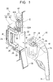
- Fig. 1 shows a charging coupler 10 and a power receiving portion 20 which jointly constitute a magnetic coupling device of this embodiment for an electric car.
- the charging coupler 10 is provided at an end of a charging power cable 11 extending from an external charging device (not shown).
- a primary coil 13, connected to the charging power cable 11, is mounted within a housing 12 of the charging coupler 10.
- the primary coil 13 is wound on a tubular body 14 of a rectangular cross-section having a thin wall, and an air core portion 15 is formed in the primary coil 13, and extends along an axis thereof.
- the primary coil 13 is fixed within the housing 12, with its axis extending in an upward-downward direction.
- spaces 16 and 16 are formed adjacent to upper and lower sides of the primary coil 13, respectively, and communicate with the air core portion 15.
- the two spaces 16 and 16 are open to the exterior through a pair of front openings 17 and 17, formed in a front surface of the housing 12, and an upper opening 18 formed in an upper surface of the housing 12.
- a fixed core 30, provided at the power receiving portion 20, is inserted into the housing 12 through the openings 17.
- a moving core 40, provided at the power receiving portion 20, is inserted into the housing 12 through the upper opening 18.
- the power receiving portion 20 has an open portion 21 which is open to an outer surface of a car body of the electric car.
- the charging coupler 10 can be inserted into the power receiving portion 20 in a direction indicated by arrow A (Fig. 1) via the open portion.
- the open portion 21 of the power receiving portion 20 can be closed by a lid 28.
- the fixed core 30 is provided within the power receiving portion 20, and is disposed inwardly of a coupler receiving space 22 for receiving the charging coupler 10.
- the fixed core 30 is formed, for example, by sintering ferrite powder, and includes a bar of a square cross-section formed into a generally C-shape with right-angled corners.
- the fixed core 30 is fixed within the power receiving portion 20 in such a manner that a vertical portion 31 of this C-shaped body is disposed at the innermost side, whereas horizontal portions 32 and 32 of the C-shaped body extend toward the open portion 21.
- a secondary coil 24 is wound on the vertical portion 31, and output terminals of the secondary coil 24 are connected to a charging circuit (not shown).
- Distal end surfaces 33 and 33 of the horizontal portions 32 and 32 are disposed in a common plane, and the moving core 40 can be moved in sliding contact with the two distal end surfaces 33 and 33.
- the power receiving portion 20 has a vertically-elongated space 22A which is disposed above the coupler receiving space 22, and communicates therewith.
- a linear drive device 41 e.g. a cylinder or a ball screw
- the moving core 40 is secured to a drive portion 41A of the linear drive device 41.
- the moving core 40 and the fixed core 30 jointly constitute a split core 23.
- the moving core 40 is formed by sintering ferrite powder, and comprises a bar of a square cross-section. An axis of the moving core 40 extends in a direction of movement of the moving core 40.
- the moving core 40 is slidingly movable between a position (see Fig. 2) where the moving core 40 is received in the vertically-elongated space 22A, and a position (see Fig. 3) where the moving core 40 is extended into the coupler receiving space 22, with opposite end portions of the moving core 40 facing the distal end surfaces 33 and 33 of the fixed core 30, respectively.
- the moving core 40 is prevented from turning about its axis so that one flat side surface 42 (see Fig. 2) of the cross-sectionally square shaped body of the moving core 40 can face the distal end surfaces 33 of the fixed core 30.
- a slanting surface 43 is formed at a lower end portion of the flat side surface 42. The slanting surface 43 can be brought into sliding contact with the distal end surfaces 33, and the moving core 40 can be moved in sliding contact with the distal end surfaces 33.
- Step portions 25 and 25 are formed respectively at the upper and lower surfaces of the coupler receiving space 22, and lock piece portions 26 and 26 are formed respectively at these step portions 25 and 25.
- the lock piece portions 26 and 26 can be engaged respectively in engagement channels 27, formed respectively in the upper and lower surfaces of the charging coupler 10, to hold the charging coupler 10 in a properly-mounted condition.
- the upper opening 18 in the charging coupler 10 faces the moving core 40 so that the moving core 40 can be inserted into the charging coupler 10.
- Detection sensors are provided respectively at the step portions 25 so as to judge whether or not the charging coupler 10 is properly mounted.
- the moving core 40 is operated in accordance with a signal from the detection sensors.
- the linear drive device 41 is operated in response to a charging completion signal from the power battery, and also can be operated by a change-over switch.
- the electric car For charging the battery device of the electric car, the electric car is parked in the vicinity of the external charging device.
- the charging coupler 10 hung at a predetermined position (for example, the side of the external charging device), is brought to the power receiving portion 20 of the electric car.
- the lid 28 of the power receiving portion 20 is opened, and then the charging coupler 10 is pushed into the power receiving portion 20.
- the horizontal portions 32 of the fixed core 30 are inserted into the charging coupler 10 respectively through the front openings 17 and 17.
- the charging coupler 10 is properly mounted, so that the lock piece portions 26 of the power receiving portion 20 are engaged respectively in the engagement channels 27 in the charging coupler 10, and also the upper opening 18 in the charging coupler 10 faces the moving core 40. Then, this condition is detected by the detection sensors, and in accordance with this detection signal, the linear drive device 41 is operated to move the moving core 40 downward into the space 16 of the charging coupler 10.
- the slanting surface 43 of the moving core 40 is brought into sliding contact with the fixed core 30, and the moving core 40 is brought into sliding contact with the distal end surface 33 of the fixed core 30, and moves downward. Then, the moving core 40 moves through the air core portion 15 of the primary coil 13, and abuts the bottom of the space 16. In this condition, the two distal end surfaces 33 and 33 of the fixed core 30 are held in contact with the opposite end portions of the moving core 40, respectively, as shown in Fig. 3, and a closed-loop magnetic circuit, passing through the primary and secondary coils 13 and 24, is formed.
- the moving core 40 is moved upward or retracted by the linear drive device 41, and is received in the vertically-elongated space 22A. Then, the charging coupler 10 is withdrawn, and is returned to the predetermined position.
- the second embodiment of the invention uses a fixed core that have a different structure than those of the first embodiment.
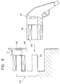
- the fixed core 50 and the moving core 51 are shown in Fig. 4.
- the fixed core 50 and the moving core 51 are both formed into an L-shape.
- the moving core 51 has an inverted L-shape and is movable in a direction indicated by arrow B into and out of contact with the fixed core 50.
- a vertical portion and a horizontal portion of the moving core 51 can be contacted at their end portions with a horizontal portion and a vertical portion of the fixed core 50 to form a closed-loop magnetic circuit.
- the rest of the structure is the same as that of the first embodiment, and therefore explanation thereof will be omitted.
- the charging coupler can also be reduced in weight as in the first embodiment.
- the fixed core 50 and the moving core 51 have the same shape, and common parts can be used, which reduces the cost.
Landscapes
- Engineering & Computer Science (AREA)
- Power Engineering (AREA)
- Transportation (AREA)
- Mechanical Engineering (AREA)
- Computer Networks & Wireless Communication (AREA)
- Charge And Discharge Circuits For Batteries Or The Like (AREA)
- Electric Propulsion And Braking For Vehicles (AREA)
Applications Claiming Priority (2)
| Application Number | Priority Date | Filing Date | Title |
|---|---|---|---|
| JP125458/97 | 1997-05-15 | ||
| JP9125458A JPH10322921A (ja) | 1997-05-15 | 1997-05-15 | 電気自動車充電用磁気結合装置 |
Publications (2)
| Publication Number | Publication Date |
|---|---|
| EP0878811A2 true EP0878811A2 (fr) | 1998-11-18 |
| EP0878811A3 EP0878811A3 (fr) | 1999-03-03 |
Family
ID=14910603
Family Applications (1)
| Application Number | Title | Priority Date | Filing Date |
|---|---|---|---|
| EP98107639A Ceased EP0878811A3 (fr) | 1997-05-15 | 1998-04-27 | Dispositif de couplage magnétique pour charger un véhicule électrique |
Country Status (4)
| Country | Link |
|---|---|
| US (1) | US6127800A (fr) |
| EP (1) | EP0878811A3 (fr) |
| JP (1) | JPH10322921A (fr) |
| CN (1) | CN1203432A (fr) |
Cited By (8)
| Publication number | Priority date | Publication date | Assignee | Title |
|---|---|---|---|---|
| GB2404094A (en) * | 2003-07-17 | 2005-01-19 | Thales Plc | A contact-less two part electrical connector |
| WO2007063500A3 (fr) * | 2005-12-02 | 2007-10-18 | Koninkl Philips Electronics Nv | Systeme de couplage |
| DE102009020504A1 (de) * | 2009-05-08 | 2010-12-02 | Sew-Eurodrive Gmbh & Co. Kg | Ladeanordnung für ein Fahrzeug und Fahrzeug |
| EP2614980A1 (fr) * | 2012-01-11 | 2013-07-17 | Tyco Electronics Nederland B.V. | Système de connecteur sans contact pour le couplage d'un véhicule électrique sur une alimentation électrique |
| EP2634780A1 (fr) * | 2012-03-02 | 2013-09-04 | Schneider Electric Industries SAS | Dispositif d'actionnement à commande électromagnétique, bornes électriques comportant un tel dispositif et dispositif de rechargement comportant de telles bornes |
| EP3709315A1 (fr) | 2019-03-15 | 2020-09-16 | ABB Schweiz AG | Coupleur à noyau fendu pour transfert de puissance inductive |
| DE102019203527A1 (de) * | 2019-03-15 | 2020-09-17 | Volkswagen Aktiengesellschaft | Vorrichtung zur induktiven Energieübertragung für einen Lastzug |
| WO2021250708A1 (fr) * | 2020-06-07 | 2021-12-16 | La Marca Francesco | Dispositif d'accouplement de wpt de type statique à mécanisme de fluage à déformation contrôlée et réglable pour stabilisation et pour blocage |
Families Citing this family (22)
| Publication number | Priority date | Publication date | Assignee | Title |
|---|---|---|---|---|
| US6859009B2 (en) * | 1999-07-02 | 2005-02-22 | Richard Jablin | Urban transportation system |
| US6727621B1 (en) * | 2003-04-22 | 2004-04-27 | Northland/Scott Fetzer Company | Motor-based electrical power supply |
| US6879233B2 (en) * | 2003-05-15 | 2005-04-12 | Yen Jen Yen | Inductor induced light emitting bottle |
| DE10360604B4 (de) | 2003-12-19 | 2020-06-18 | Sew-Eurodrive Gmbh & Co Kg | Verbraucher mit Mittel zu seiner induktiven Versorgung und System |
| DE102005022367B4 (de) | 2005-05-10 | 2021-05-20 | Sew-Eurodrive Gmbh & Co Kg | Berührungslos versorgter Verbraucher und System |
| DE102005022648B4 (de) * | 2005-05-11 | 2021-05-27 | Sew-Eurodrive Gmbh & Co Kg | Anlage mit berührungslos versorgtem Verbraucher |
| KR101948276B1 (ko) * | 2009-02-05 | 2019-02-14 | 오클랜드 유니서비시즈 리미티드 | 유도 전력 전송 장치 |
| US8405346B2 (en) * | 2009-02-17 | 2013-03-26 | Diversified Power International, Llc | Inductively coupled power transfer assembly |
| US20110221387A1 (en) * | 2010-03-09 | 2011-09-15 | Robert Louis Steigerwald | System and method for charging an energy storage system for an electric or hybrid-electric vehicle |
| US8725330B2 (en) | 2010-06-02 | 2014-05-13 | Bryan Marc Failing | Increasing vehicle security |
| JP5895631B2 (ja) * | 2012-03-16 | 2016-03-30 | アイシン精機株式会社 | 車両給電装置 |
| USD706618S1 (en) * | 2012-05-18 | 2014-06-10 | Elliott Brenghause | Window locking bracket |
| KR101449197B1 (ko) * | 2012-12-26 | 2014-10-08 | 현대자동차주식회사 | 전기자동차 충전용 자성커넥터 장치 |
| US9419468B1 (en) * | 2013-12-20 | 2016-08-16 | Amazon Technologies, Inc. | Inductive charging system |
| CN105098998B (zh) * | 2014-05-16 | 2020-02-11 | 泰科电子(上海)有限公司 | 无线电力传输装置 |
| DE102014222000A1 (de) * | 2014-10-29 | 2016-05-04 | Bayerische Motoren Werke Aktiengesellschaft | Verfahren und Bodeneinheit zum induktiven Laden von Elektro- und Hybridfahrzeugen |
| DE102015223615B4 (de) * | 2015-11-30 | 2025-03-20 | Bayerische Motoren Werke Aktiengesellschaft | Sekundärspuleneinheit mit einer Service-Öffnung |
| CN106347166B (zh) * | 2016-11-22 | 2018-09-18 | 飞洲集团有限公司 | 一种电动车辆的整体冷却充电装置 |
| JP7260409B2 (ja) * | 2019-06-14 | 2023-04-18 | 本田技研工業株式会社 | 自律走行作業機、及び無線給電システム |
| CN115195503B (zh) * | 2021-04-08 | 2025-09-09 | 香港理工大学 | 磁耦合充电系统和磁耦合充电方法 |
| TWI804939B (zh) * | 2021-07-30 | 2023-06-11 | 帥群微電子股份有限公司 | 無線充電系統及其充電站 |
| US12172476B1 (en) * | 2021-12-09 | 2024-12-24 | Amazon Technologies, Inc. | Coupler with magnetic element for towing utility carts |
Family Cites Families (10)
| Publication number | Priority date | Publication date | Assignee | Title |
|---|---|---|---|---|
| GB1501502A (en) * | 1975-01-08 | 1978-02-15 | Pelcon Ltd | Inductive connectors |
| US5341083A (en) * | 1991-09-27 | 1994-08-23 | Electric Power Research Institute, Inc. | Contactless battery charging system |
| EP0552737A1 (fr) * | 1992-01-22 | 1993-07-28 | Hughes Aircraft Company | Chargeur résistant aux intempéries monté lelong |
| US5637973A (en) * | 1992-06-18 | 1997-06-10 | Kabushiki Kaisha Yaskawa Denki | Noncontacting electric power transfer apparatus, noncontacting signal transfer apparatus, split-type mechanical apparatus employing these transfer apparatus and a control method for controlling same |
| US5264776A (en) * | 1992-06-30 | 1993-11-23 | Hughes Aircraft Company | Electric vehicle inductive coupling charge port |
| JPH06189479A (ja) * | 1992-12-15 | 1994-07-08 | Toyota Autom Loom Works Ltd | 電磁給電装置 |
| JPH06197479A (ja) * | 1992-12-24 | 1994-07-15 | Toyota Autom Loom Works Ltd | 電磁給電装置 |
| JPH06197480A (ja) * | 1992-12-25 | 1994-07-15 | Toyota Autom Loom Works Ltd | 電磁給電装置 |
| US5680028A (en) * | 1994-06-30 | 1997-10-21 | Mceachern; Alexander | Charger for hand-held rechargeable electric apparatus with reduced magnetic field |
| DE69714879T2 (de) * | 1996-01-30 | 2003-05-08 | Sumitomo Wiring Systems, Ltd. | Verbindungssystem mit zugehörigem Verfahren |
-
1997
- 1997-05-15 JP JP9125458A patent/JPH10322921A/ja active Pending
-
1998
- 1998-04-27 EP EP98107639A patent/EP0878811A3/fr not_active Ceased
- 1998-05-05 CN CN98107872A patent/CN1203432A/zh active Pending
- 1998-05-13 US US09/076,861 patent/US6127800A/en not_active Expired - Fee Related
Cited By (14)
| Publication number | Priority date | Publication date | Assignee | Title |
|---|---|---|---|---|
| GB2404094B (en) * | 2003-07-17 | 2008-01-02 | Thales Plc | Electrical connector |
| GB2404094A (en) * | 2003-07-17 | 2005-01-19 | Thales Plc | A contact-less two part electrical connector |
| WO2007063500A3 (fr) * | 2005-12-02 | 2007-10-18 | Koninkl Philips Electronics Nv | Systeme de couplage |
| US7825544B2 (en) | 2005-12-02 | 2010-11-02 | Koninklijke Philips Electronics N.V. | Coupling system |
| DE102009020504B4 (de) | 2009-05-08 | 2023-08-17 | Sew-Eurodrive Gmbh & Co Kg | Ladeanordnung für ein Fahrzeug und Fahrzeug |
| DE102009020504A1 (de) * | 2009-05-08 | 2010-12-02 | Sew-Eurodrive Gmbh & Co. Kg | Ladeanordnung für ein Fahrzeug und Fahrzeug |
| EP2614980A1 (fr) * | 2012-01-11 | 2013-07-17 | Tyco Electronics Nederland B.V. | Système de connecteur sans contact pour le couplage d'un véhicule électrique sur une alimentation électrique |
| EP2634780A1 (fr) * | 2012-03-02 | 2013-09-04 | Schneider Electric Industries SAS | Dispositif d'actionnement à commande électromagnétique, bornes électriques comportant un tel dispositif et dispositif de rechargement comportant de telles bornes |
| FR2987694A1 (fr) * | 2012-03-02 | 2013-09-06 | Schneider Electric Ind Sas | Dispositif d'actionnement a commande electromagnetique, bornes electriques comportant un tel dispositif et dispositif de rechargement comportant de telles bornes |
| EP3709315A1 (fr) | 2019-03-15 | 2020-09-16 | ABB Schweiz AG | Coupleur à noyau fendu pour transfert de puissance inductive |
| DE102019203527A1 (de) * | 2019-03-15 | 2020-09-17 | Volkswagen Aktiengesellschaft | Vorrichtung zur induktiven Energieübertragung für einen Lastzug |
| DE102019203527B4 (de) | 2019-03-15 | 2024-05-08 | Volkswagen Aktiengesellschaft | Vorrichtung zur induktiven Energieübertragung für einen Lastzug |
| WO2021250708A1 (fr) * | 2020-06-07 | 2021-12-16 | La Marca Francesco | Dispositif d'accouplement de wpt de type statique à mécanisme de fluage à déformation contrôlée et réglable pour stabilisation et pour blocage |
| CN116210064A (zh) * | 2020-06-07 | 2023-06-02 | 莫比健康(股份)责任有限公司 | 用于稳定和阻挡且具可控和可调节变形的屈服机构的静态wpt耦合装置 |
Also Published As
| Publication number | Publication date |
|---|---|
| US6127800A (en) | 2000-10-03 |
| CN1203432A (zh) | 1998-12-30 |
| EP0878811A3 (fr) | 1999-03-03 |
| JPH10322921A (ja) | 1998-12-04 |
Similar Documents
| Publication | Publication Date | Title |
|---|---|---|
| US6127800A (en) | Magnetic coupling device for charging an electric car which includes split cores provided at one of a power receiving portion and a charging coupler | |
| JP2581640B2 (ja) | 壁または天井に設置される誘電型充電装置 | |
| US5070293A (en) | Electric power transmitting device with inductive coupling | |
| JP3586955B2 (ja) | 電気自動車用充電システム | |
| JP3870315B2 (ja) | 移動体システム | |
| US5661391A (en) | Apparatus for charging a propulsion battery of an electrically powered vehicle | |
| EP0143780B1 (fr) | Appareil pour charger les batteries d'un vehicule | |
| DE69711963T2 (de) | Verbindungssystem und -verfahren für ein elektrisch betriebenes Fahrzeug | |
| EP0788211A2 (fr) | Système de connexion et méthode de connexion | |
| EP0552737A1 (fr) | Chargeur résistant aux intempéries monté lelong | |
| US6042385A (en) | Connector for charging | |
| JP3724030B2 (ja) | ワゴン台車装置 | |
| JP2986368B2 (ja) | 手応えを与える手段を有する誘導型カプラ | |
| JP2000152512A (ja) | 充電装置 | |
| CN207228801U (zh) | 一种电子锁、充电插座及电动车辆 | |
| CN109149263B (zh) | 一种电子锁及使用该电子锁的充电插座、电动车辆 | |
| JP2013090392A (ja) | 非接触充電装置及び非接触給電設備 | |
| JPH05111168A (ja) | 電気自動車のバツテリの充電装置 | |
| EP3823889B1 (fr) | Système de transformateur magnétique de charge sans fil | |
| JP5962605B2 (ja) | リーチ式電動フォークリフトの非接触充電システム | |
| JPH1118306A (ja) | 電気自動車充電用コネクタ | |
| JP5497374B2 (ja) | 立体駐車装置 | |
| JPH04236102A (ja) | 無人搬送装置における充電方式 | |
| JPH06140256A (ja) | 電力伝達装置 | |
| JP2001028801A (ja) | 搬送台車の充電方法及び充電装置並びにその充電装置を用いた搬送システム |
Legal Events
| Date | Code | Title | Description |
|---|---|---|---|
| PUAI | Public reference made under article 153(3) epc to a published international application that has entered the european phase |
Free format text: ORIGINAL CODE: 0009012 |
|
| AK | Designated contracting states |
Kind code of ref document: A2 Designated state(s): DE FR GB IT |
|
| AX | Request for extension of the european patent |
Free format text: AL;LT;LV;MK;RO;SI |
|
| PUAL | Search report despatched |
Free format text: ORIGINAL CODE: 0009013 |
|
| AK | Designated contracting states |
Kind code of ref document: A3 Designated state(s): AT BE CH CY DE DK ES FI FR GB GR IE IT LI LU MC NL PT SE |
|
| AX | Request for extension of the european patent |
Free format text: AL;LT;LV;MK;RO;SI |
|
| 17P | Request for examination filed |
Effective date: 19990805 |
|
| 17Q | First examination report despatched |
Effective date: 19990920 |
|
| AKX | Designation fees paid |
Free format text: DE FR GB IT |
|
| GRAG | Despatch of communication of intention to grant |
Free format text: ORIGINAL CODE: EPIDOS AGRA |
|
| STAA | Information on the status of an ep patent application or granted ep patent |
Free format text: STATUS: THE APPLICATION HAS BEEN REFUSED |
|
| 18R | Application refused |
Effective date: 20010625 |