EP0878867A2 - Connecteur pour câble flexible plat - Google Patents
Connecteur pour câble flexible plat Download PDFInfo
- Publication number
- EP0878867A2 EP0878867A2 EP98303650A EP98303650A EP0878867A2 EP 0878867 A2 EP0878867 A2 EP 0878867A2 EP 98303650 A EP98303650 A EP 98303650A EP 98303650 A EP98303650 A EP 98303650A EP 0878867 A2 EP0878867 A2 EP 0878867A2
- Authority
- EP
- European Patent Office
- Prior art keywords
- housing
- flat cable
- flexible flat
- cap plate
- contacts
- Prior art date
- Legal status (The legal status is an assumption and is not a legal conclusion. Google has not performed a legal analysis and makes no representation as to the accuracy of the status listed.)
- Granted
Links
Images


Classifications
-
- H—ELECTRICITY
- H01—ELECTRIC ELEMENTS
- H01R—ELECTRICALLY-CONDUCTIVE CONNECTIONS; STRUCTURAL ASSOCIATIONS OF A PLURALITY OF MUTUALLY-INSULATED ELECTRICAL CONNECTING ELEMENTS; COUPLING DEVICES; CURRENT COLLECTORS
- H01R12/00—Structural associations of a plurality of mutually-insulated electrical connecting elements, specially adapted for printed circuits, e.g. printed circuit boards [PCB], flat or ribbon cables, or like generally planar structures, e.g. terminal strips, terminal blocks; Coupling devices specially adapted for printed circuits, flat or ribbon cables, or like generally planar structures; Terminals specially adapted for contact with, or insertion into, printed circuits, flat or ribbon cables, or like generally planar structures
- H01R12/70—Coupling devices
- H01R12/77—Coupling devices for flexible printed circuits, flat or ribbon cables or like structures
- H01R12/79—Coupling devices for flexible printed circuits, flat or ribbon cables or like structures connecting to rigid printed circuits or like structures
-
- H—ELECTRICITY
- H01—ELECTRIC ELEMENTS
- H01R—ELECTRICALLY-CONDUCTIVE CONNECTIONS; STRUCTURAL ASSOCIATIONS OF A PLURALITY OF MUTUALLY-INSULATED ELECTRICAL CONNECTING ELEMENTS; COUPLING DEVICES; CURRENT COLLECTORS
- H01R12/00—Structural associations of a plurality of mutually-insulated electrical connecting elements, specially adapted for printed circuits, e.g. printed circuit boards [PCB], flat or ribbon cables, or like generally planar structures, e.g. terminal strips, terminal blocks; Coupling devices specially adapted for printed circuits, flat or ribbon cables, or like generally planar structures; Terminals specially adapted for contact with, or insertion into, printed circuits, flat or ribbon cables, or like generally planar structures
- H01R12/70—Coupling devices
- H01R12/77—Coupling devices for flexible printed circuits, flat or ribbon cables or like structures
- H01R12/78—Coupling devices for flexible printed circuits, flat or ribbon cables or like structures connecting to other flexible printed circuits, flat or ribbon cables or like structures
Definitions
- the present invention relates to a small connector used for connecting a flexible flat cable to a printed circuit board (especially a flexible board), and in particular to a low-profile small connector on which multiple contacts are mounted at a short arrangement pitch.
- a flexible flat cable including a flexible printed circuit (called an FPC) cable
- an FPC flexible printed circuit
- ZIF zero insertion force
- a connector disclosed in Utility Model Laid-open Japenese Publication 6-88083 (1994).
- a lever For the first connector after the attachment of a cable a lever must be rotated in order for a cable electrode (or a conductive contact) to make contact with the contact of the connector, and special equipment is required to automate the job of assembling the cable and the connector.
- a reinforcement plate (a cover) is attached to the surface of a cable and the cable with the reinforcement plate is directly assembled with the connector, the reinforcement plate engages a guide formed on the connector during the assembly of the cable and the connector to thereby position the cable correctly.
- a connector according to the present invention has been developed in order to eliminate one or more of the above problems of the conventional connector.
- a connector used for a flexible flat cable comprising a housing having a plurality of contacts mounted therein, and a cap plate for capping and retaining a flexible flat cable set in the housing, wherein the housing includes an opening for receiving the flexible flat cable and a recess formed substantially in the center of the opening in the longitudinal direction of the housing, and each of the plurality of the contacts comprises a contact portion extending into the recess and a leg portion extending externally, the contacts being mounted at a predetermined pitch in the longitudinal direction of the housing, wherein the cap plate caps and holds the flexible flat cable inserted through the opening in the housing, and brings conductive contact portions of the flexible flat cable into contact with corresponding contacts in the housing to establish electrical connections, and wherein the housing and the cap plate have latching means for latching means for latching them to retain the flexible flat cable positioned in the housing.
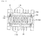
- Figure 1 is a plan view showing a connector according to the present invention.
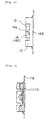
- Figure 2 is a side view showing the connector shown in figure 1.
- Figure 3 is a sectional view showing the connector shown in figure 1.
- Figure 4 is a perspective view showing a cover plate of the connector according to the present invention.
- Figure 5 is a sectional view showing a state of the connector being used.
- Figure 6 is a view showing a case where the connector shown in figure 1 is mounted on a printed circuit board.
- a connector according to the present invention which is used for flexible flat cable, comprises a housing 10 on which a plurality of contacts 11 are mounted; and a cap plate 20 for capping and retaining a flexible flat cable 100 that is positioned in the housing.
- a housing 10 on which a plurality of contacts 11 are mounted
- a cap plate 20 for capping and retaining a flexible flat cable 100 that is positioned in the housing.
- FIG. 1 to 3 is shown the housing of the connector of the present invention, and in figure 4 is shown the cap plate.
- the external shape of the entire housing is a square, and provided in the housing are an opening 12 for accepting and positioning the flexible flat cable, and a recess 13 formed substantially in the center of the opening and extending in the longitudinal direction of the housing (the ridge (protrusion) of the cap plate engages the recess with the cable positioned in between, as will be described later).
- the contacts are arranged at a constant pitch at the bottom of the opening in the housing and along the long sides of the hcusing that face each other.
- contact portions 11A of the contacts extend inside the recess in the housing
- leg portions 11B of the contacts extend outward
- the main body between the contact portions and the leg portions of the contacts is securely fixed or embedded in grooves formed in the facing sides of the housing.
- the contact portions of the contacts are leaf springs, which alternately project into the recess from the sides of the housing located opposite each other.
- the cap plate caps and holds the fexible flat cable, which is inserted into the opening in the housing, and brings conductive contact portions 100A of the flexible flat cable into contact with the corresponding contacts in the housing to provide electrical connections (see Figure 5). At this time, if the contact portions of the contacts, which are mounted on the housing, are sufficiently wide and cover the contact positions of the conductive contact portions of the flexible flat cable, precisely aligned electrical connections of the contacts and the contact portions of the cable can be obtained.
- the housing and the cap plate have latching means for latching them to each other, and when the two are latched, they are positioned in the housing that they hold the flexible flat cable.
- the latching means comprises paired protrusions 22, which, as is shown in Figure 4, are formed along the short sides of the cap plate that face each other, and paired latch plates 14, which, as is shown in Figures 1 to 3, are mounted on the short sides of the housing that face each other.
- the latch plates each include a latch portion 14A, latch portions 14C (see Figure 1) and a base portion 14B (see Figures 1 and 2), with the first two portions being raised from the base portion. Both ends of the base portion 14B of the latch plate extend outside the housing, and are soldered, with the legs of the contacts, to conductive pads 31 (see Figure 6) on a printed board 30 (see Figure 5), for example. Grooves 14a are formed in the latch portions of the latch plate to engage the protrusions 22 on the cap plate. The latch portions 14C on the latch plate are fixed to the grooves that are formed in the short sides of the housing that face each other.
- a ridge 21 is formed on the cap plate in its longitudinal direction, and is fitted into the recess in the housing when the housing engages the cap plate.
- FIG 6 is shown a case where the flexible flat cable connector according to the present invention is automatically mounted on a flexible printed board.
- an automated mounting apparatus holds and moves the housing of the connector by using a tape 40 attached to the surface of the housing.
- the cap plate caps and holds the flexible flat cable inserted into the opening in the housing (especially the ridge (the protrusion) formed on the cap plate that engages the recess in the housing via the cable), unlike the conventional connector, the process for attaching a reinforcement plate (cover plate) to the surface of the cable is not required.
- the accuracy of the positioning of the cable is not affected by the precision of the attachment of the reinforcement plate, and the engagement of the cover plate with the recess in the housing can correctly position the cable.
- the ridge of the cap plate engages the recess in the housing via a cable
- the force available for holding the cable and the strength of the connector can be increased, when compared with the conventional connector where the flat cover simply engages the housing.
- the thickness (the height) of the connector can be adequately reduced.
Landscapes
- Coupling Device And Connection With Printed Circuit (AREA)
- Multi-Conductor Connections (AREA)
- Details Of Connecting Devices For Male And Female Coupling (AREA)
Applications Claiming Priority (3)
| Application Number | Priority Date | Filing Date | Title |
|---|---|---|---|
| JP119544/97 | 1997-05-09 | ||
| JP11954497 | 1997-05-09 | ||
| JP9119544A JPH10312841A (ja) | 1997-05-09 | 1997-05-09 | 可撓性フラットケーブル用コネクタ |
Publications (3)
| Publication Number | Publication Date |
|---|---|
| EP0878867A2 true EP0878867A2 (fr) | 1998-11-18 |
| EP0878867A3 EP0878867A3 (fr) | 2000-12-20 |
| EP0878867B1 EP0878867B1 (fr) | 2004-08-18 |
Family
ID=14763939
Family Applications (1)
| Application Number | Title | Priority Date | Filing Date |
|---|---|---|---|
| EP98303650A Expired - Lifetime EP0878867B1 (fr) | 1997-05-09 | 1998-05-08 | Connecteur pour câble flexible plat |
Country Status (5)
| Country | Link |
|---|---|
| US (1) | US6022242A (fr) |
| EP (1) | EP0878867B1 (fr) |
| JP (1) | JPH10312841A (fr) |
| CA (1) | CA2237207C (fr) |
| DE (1) | DE69825666T2 (fr) |
Cited By (1)
| Publication number | Priority date | Publication date | Assignee | Title |
|---|---|---|---|---|
| SG97172A1 (en) * | 1999-12-17 | 2003-07-18 | Connector Systems Tech Nv | Connector for a flat cable |
Families Citing this family (3)
| Publication number | Priority date | Publication date | Assignee | Title |
|---|---|---|---|---|
| JP3768170B2 (ja) * | 2002-05-09 | 2006-04-19 | 山一電機株式会社 | ケーブル用コネクタ |
| US6932642B2 (en) * | 2003-05-06 | 2005-08-23 | Delphi Technologies, Inc. | Low insertion force connector |
| WO2014002889A1 (fr) * | 2012-06-27 | 2014-01-03 | 矢崎総業株式会社 | Connecteur multifilaire flexible |
Family Cites Families (48)
| Publication number | Priority date | Publication date | Assignee | Title |
|---|---|---|---|---|
| US3082398A (en) * | 1960-05-24 | 1963-03-19 | Amphenol Borg Electronics Corp | Electrical connectors |
| US3084302A (en) * | 1960-12-01 | 1963-04-02 | Hughes Aircraft Co | Electrical ribbon cable connector |
| US3114587A (en) * | 1961-10-02 | 1963-12-17 | Adolf L Herrmann | Flat cables and corresponding connector |
| US3278887A (en) * | 1964-03-16 | 1966-10-11 | Westinghouse Electric Corp | Electrical circuit assembly and method of manufacture |
| US3319216A (en) * | 1965-03-25 | 1967-05-09 | Fischer & Porter Co | Connector for flat cables |
| US3393392A (en) * | 1966-04-27 | 1968-07-16 | Rca Corp | Printed circuit connector |
| GB1180027A (en) * | 1966-06-22 | 1970-02-04 | Lucas Industries Ltd | Connectors for Use in with Flexible Printed Circuits. |
| US3486216A (en) * | 1967-10-17 | 1969-12-30 | Gerald N Cimolino | Co-axial cable stripping,trimming and cutting tool |
| US3696319A (en) * | 1970-08-20 | 1972-10-03 | Berg Electronics Inc | Flat conductor cable connector |
| JPS498168A (fr) * | 1972-05-10 | 1974-01-24 | ||
| US3772775A (en) * | 1972-07-17 | 1973-11-20 | Methods Electronics Inc | Method of making flat conductor cable assemblies |
| US3897130A (en) * | 1973-12-03 | 1975-07-29 | Itt | Flat cable connector |
| US4235500A (en) * | 1978-11-08 | 1980-11-25 | Trw Inc. | Circuit connector |
| US4265507A (en) * | 1979-08-06 | 1981-05-05 | Teledyne Industries, Inc. | Electrical connector for strip conductors |
| US4379608A (en) * | 1981-03-11 | 1983-04-12 | Amp Incorporated | Flat cable to planar circuit connector |
| US4422700A (en) * | 1982-01-06 | 1983-12-27 | Heath Company | Grounded multi-pin connector for shielded flat cable |
| JPS60109280A (ja) * | 1983-11-18 | 1985-06-14 | Hitachi Ltd | 半導体装置の製造方法 |
| US4573752A (en) * | 1984-04-04 | 1986-03-04 | Parlex Corporation | Flat cable connection system |
| US4640562A (en) * | 1984-12-19 | 1987-02-03 | Amp Incorporated | Surface mounting means for printed circuit board |
| US4750881A (en) * | 1985-03-07 | 1988-06-14 | Oki Electric Industry Co., Ltd. | Easily assembled carriage mechanism of printer |
| JPH0665090B2 (ja) * | 1985-09-06 | 1994-08-22 | Fpcコネクタ | |
| US4639063A (en) * | 1985-12-20 | 1987-01-27 | Amp Incorporated | Electrical connector for flexible film circuits |
| US4681382A (en) * | 1985-12-20 | 1987-07-21 | Amp Incorporated | Electrical connector for transmission cable |
| JPH0455421Y2 (fr) * | 1986-11-28 | 1992-12-25 | ||
| US4740867A (en) * | 1987-03-26 | 1988-04-26 | Advanced Circuit Technology, Inc. | Printed circuit connection system |
| JPS63274074A (ja) * | 1987-05-01 | 1988-11-11 | アンプ インコ−ポレ−テツド | 電気コンタクトアセンブリおよびその製造方法 |
| JPH088550Y2 (ja) * | 1988-01-14 | 1996-03-06 | アンプ インコーポレーテッド | フラットケーブル用コネクタ |
| JPH0665092B2 (ja) * | 1989-06-27 | 1994-08-22 | 矢崎総業株式会社 | コネクタ |
| JPH0635413Y2 (ja) * | 1989-07-10 | 1994-09-14 | ホシデン株式会社 | コネクタ |
| US4971575A (en) * | 1989-07-14 | 1990-11-20 | North American Specialties Of California, Inc. | High density connector |
| US4938702A (en) * | 1989-09-22 | 1990-07-03 | Key Tronic Corporation | Connector clamp for attaching flat electrical conductor leads to printed wiring boards |
| US5044980A (en) * | 1990-01-16 | 1991-09-03 | Beta Phase, Inc. | High density and multiple insertion connector |
| US5030794A (en) * | 1990-02-14 | 1991-07-09 | Rlp Tool Co. | Accessory RF shields for multiple-line ribbon cables |
| US5097099A (en) * | 1991-01-09 | 1992-03-17 | Amp Incorporated | Hybrid branch cable and shield |
| US5209671A (en) * | 1991-03-28 | 1993-05-11 | Sharp Kabushiki Kaisha | Electric connection structure between circuit boards |
| US5507651A (en) * | 1991-04-22 | 1996-04-16 | Kel Corporation | Connector assembly for film circuitry |
| US5262590A (en) * | 1992-04-27 | 1993-11-16 | Sheldahl, Inc. | Impedance controlled flexible circuits with fold-over shields |
| JP2622528B2 (ja) * | 1992-08-24 | 1997-06-18 | 日本航空電子工業株式会社 | Fpc接続用コネクタ |
| JPH0688083A (ja) * | 1992-09-07 | 1994-03-29 | Kunio Kato | 可燃廃棄物の固形燃料製造方法 |
| US5297968A (en) * | 1993-01-12 | 1994-03-29 | The Whitaker Corporation | Pluggable connector systems for flexible etched circuits |
| JP3285242B2 (ja) * | 1993-01-25 | 2002-05-27 | 矢崎総業株式会社 | コネクタ構造 |
| MY131437A (en) * | 1993-01-29 | 2007-08-30 | Minnesota Mining & Mfg | Flexible circuit connector |
| US5383788A (en) * | 1993-05-20 | 1995-01-24 | W. L. Gore & Associates, Inc. | Electrical interconnect assembly |
| US5403202A (en) * | 1993-10-07 | 1995-04-04 | Hewlett-Packard Company | Low insertion force/low profile flex connector |
| US5428187A (en) * | 1994-02-24 | 1995-06-27 | Molex Incorporated | Shielded hybrid ribbon cable assembly |
| US5529502A (en) * | 1994-06-01 | 1996-06-25 | Motorola, Inc. | Solderless flexible circuit carrier to printed circuit board interconnection |
| US5616050A (en) * | 1995-01-19 | 1997-04-01 | Ast Research Inc. | Flexible circuit connector |
| JP2981829B2 (ja) * | 1995-01-31 | 1999-11-22 | 日本航空電子工業株式会社 | 可撓導通部材用コネクタ |
-
1997
- 1997-05-09 JP JP9119544A patent/JPH10312841A/ja active Pending
-
1998
- 1998-05-08 DE DE69825666T patent/DE69825666T2/de not_active Expired - Fee Related
- 1998-05-08 EP EP98303650A patent/EP0878867B1/fr not_active Expired - Lifetime
- 1998-05-08 US US09/074,746 patent/US6022242A/en not_active Expired - Fee Related
- 1998-05-08 CA CA002237207A patent/CA2237207C/fr not_active Expired - Fee Related
Cited By (1)
| Publication number | Priority date | Publication date | Assignee | Title |
|---|---|---|---|---|
| SG97172A1 (en) * | 1999-12-17 | 2003-07-18 | Connector Systems Tech Nv | Connector for a flat cable |
Also Published As
| Publication number | Publication date |
|---|---|
| DE69825666D1 (de) | 2004-09-23 |
| JPH10312841A (ja) | 1998-11-24 |
| EP0878867B1 (fr) | 2004-08-18 |
| CA2237207C (fr) | 2007-01-02 |
| EP0878867A3 (fr) | 2000-12-20 |
| CA2237207A1 (fr) | 1998-11-09 |
| DE69825666T2 (de) | 2005-01-05 |
| US6022242A (en) | 2000-02-08 |
Similar Documents
| Publication | Publication Date | Title |
|---|---|---|
| US11233346B2 (en) | Board-to-board connector | |
| KR100344048B1 (ko) | Pga 패키지용의 점검 가능한 전기 커넥터 | |
| CN110061375A (zh) | 连接器、对接连接器以及连接器组件 | |
| US5883787A (en) | Floating guided connector and method | |
| US6450824B1 (en) | Connector including movable cover | |
| KR20000077105A (ko) | 핀 격자 어레이 패키지용 소켓 조립체 및 이를 위한 단자 | |
| CN101283485A (zh) | 连接器 | |
| JP4115974B2 (ja) | ゼロ挿入力電気コネクタ | |
| US6554634B1 (en) | Electrical contact for ZIF socket connector | |
| US6022242A (en) | Connector used for flexible flat cable | |
| EP0269241A2 (fr) | Connecteur électrique comprenant une combinaison d'adaptateurs individuels et de fiches comme membre de contact | |
| US6976890B2 (en) | Electrical connector for connecting a mating contact and a connection object | |
| US4735585A (en) | Interplane connector | |
| EP1133008A2 (fr) | Dispositif de connexion électrique | |
| JPH077184U (ja) | 回路基板の収納ハウジングの構造 | |
| US6296503B1 (en) | Socket for an electric part | |
| JP3268253B2 (ja) | 電気部品用ソケット | |
| JP3535365B2 (ja) | 半導体装置用ソケット | |
| JPH0570273B2 (fr) | ||
| JP3467427B2 (ja) | コネクタの装着構造 | |
| JP3706463B2 (ja) | 基板に実装されたコネクタの接続方法 | |
| JP2564278Y2 (ja) | フレキシブル導体接続用コネクタ | |
| JP2026058139A (ja) | ガイド部品 | |
| CN1972020A (zh) | 连接器 | |
| EP1768476B1 (fr) | Connecteur |
Legal Events
| Date | Code | Title | Description |
|---|---|---|---|
| PUAI | Public reference made under article 153(3) epc to a published international application that has entered the european phase |
Free format text: ORIGINAL CODE: 0009012 |
|
| AK | Designated contracting states |
Kind code of ref document: A2 Designated state(s): BE CH DE ES FR GB IT LI LU NL SE |
|
| AX | Request for extension of the european patent |
Free format text: AL;LT;LV;MK;RO;SI |
|
| PUAL | Search report despatched |
Free format text: ORIGINAL CODE: 0009013 |
|
| AK | Designated contracting states |
Kind code of ref document: A3 Designated state(s): AT BE CH CY DE DK ES FI FR GB GR IE IT LI LU MC NL PT SE |
|
| AX | Request for extension of the european patent |
Free format text: AL;LT;LV;MK;RO;SI |
|
| 17P | Request for examination filed |
Effective date: 20010615 |
|
| AKX | Designation fees paid |
Free format text: BE CH DE ES FR GB IT LI LU NL SE |
|
| 17Q | First examination report despatched |
Effective date: 20030904 |
|
| GRAP | Despatch of communication of intention to grant a patent |
Free format text: ORIGINAL CODE: EPIDOSNIGR1 |
|
| GRAS | Grant fee paid |
Free format text: ORIGINAL CODE: EPIDOSNIGR3 |
|
| GRAA | (expected) grant |
Free format text: ORIGINAL CODE: 0009210 |
|
| AK | Designated contracting states |
Kind code of ref document: B1 Designated state(s): BE CH DE ES FR GB IT LI LU NL SE |
|
| PG25 | Lapsed in a contracting state [announced via postgrant information from national office to epo] |
Ref country code: NL Free format text: LAPSE BECAUSE OF FAILURE TO SUBMIT A TRANSLATION OF THE DESCRIPTION OR TO PAY THE FEE WITHIN THE PRESCRIBED TIME-LIMIT Effective date: 20040818 Ref country code: LI Free format text: LAPSE BECAUSE OF FAILURE TO SUBMIT A TRANSLATION OF THE DESCRIPTION OR TO PAY THE FEE WITHIN THE PRESCRIBED TIME-LIMIT Effective date: 20040818 Ref country code: IT Free format text: LAPSE BECAUSE OF FAILURE TO SUBMIT A TRANSLATION OF THE DESCRIPTION OR TO PAY THE FEE WITHIN THE PRESCRIBED TIME-LIMIT;WARNING: LAPSES OF ITALIAN PATENTS WITH EFFECTIVE DATE BEFORE 2007 MAY HAVE OCCURRED AT ANY TIME BEFORE 2007. THE CORRECT EFFECTIVE DATE MAY BE DIFFERENT FROM THE ONE RECORDED. Effective date: 20040818 Ref country code: CH Free format text: LAPSE BECAUSE OF FAILURE TO SUBMIT A TRANSLATION OF THE DESCRIPTION OR TO PAY THE FEE WITHIN THE PRESCRIBED TIME-LIMIT Effective date: 20040818 Ref country code: BE Free format text: LAPSE BECAUSE OF FAILURE TO SUBMIT A TRANSLATION OF THE DESCRIPTION OR TO PAY THE FEE WITHIN THE PRESCRIBED TIME-LIMIT Effective date: 20040818 |
|
| REG | Reference to a national code |
Ref country code: GB Ref legal event code: FG4D |
|
| RIC1 | Information provided on ipc code assigned before grant |
Ipc: 7H 01R 12/24 B Ipc: 7H 01R 12/16 A |
|
| REG | Reference to a national code |
Ref country code: CH Ref legal event code: EP |
|
| REF | Corresponds to: |
Ref document number: 69825666 Country of ref document: DE Date of ref document: 20040923 Kind code of ref document: P |
|
| PG25 | Lapsed in a contracting state [announced via postgrant information from national office to epo] |
Ref country code: SE Free format text: LAPSE BECAUSE OF FAILURE TO SUBMIT A TRANSLATION OF THE DESCRIPTION OR TO PAY THE FEE WITHIN THE PRESCRIBED TIME-LIMIT Effective date: 20041118 |
|
| PG25 | Lapsed in a contracting state [announced via postgrant information from national office to epo] |
Ref country code: ES Free format text: LAPSE BECAUSE OF FAILURE TO SUBMIT A TRANSLATION OF THE DESCRIPTION OR TO PAY THE FEE WITHIN THE PRESCRIBED TIME-LIMIT Effective date: 20041129 |
|
| NLV1 | Nl: lapsed or annulled due to failure to fulfill the requirements of art. 29p and 29m of the patents act | ||
| REG | Reference to a national code |
Ref country code: CH Ref legal event code: PL |
|
| PG25 | Lapsed in a contracting state [announced via postgrant information from national office to epo] |
Ref country code: LU Free format text: LAPSE BECAUSE OF NON-PAYMENT OF DUE FEES Effective date: 20050508 |
|
| ET | Fr: translation filed | ||
| PLBE | No opposition filed within time limit |
Free format text: ORIGINAL CODE: 0009261 |
|
| STAA | Information on the status of an ep patent application or granted ep patent |
Free format text: STATUS: NO OPPOSITION FILED WITHIN TIME LIMIT |
|
| 26N | No opposition filed |
Effective date: 20050519 |
|
| PGFP | Annual fee paid to national office [announced via postgrant information from national office to epo] |
Ref country code: DE Payment date: 20080630 Year of fee payment: 11 |
|
| PGFP | Annual fee paid to national office [announced via postgrant information from national office to epo] |
Ref country code: GB Payment date: 20080529 Year of fee payment: 11 |
|
| GBPC | Gb: european patent ceased through non-payment of renewal fee |
Effective date: 20090508 |
|
| REG | Reference to a national code |
Ref country code: FR Ref legal event code: ST Effective date: 20100129 |
|
| PG25 | Lapsed in a contracting state [announced via postgrant information from national office to epo] |
Ref country code: FR Free format text: LAPSE BECAUSE OF NON-PAYMENT OF DUE FEES Effective date: 20090602 |
|
| PGFP | Annual fee paid to national office [announced via postgrant information from national office to epo] |
Ref country code: FR Payment date: 20080519 Year of fee payment: 11 |
|
| PG25 | Lapsed in a contracting state [announced via postgrant information from national office to epo] |
Ref country code: GB Free format text: LAPSE BECAUSE OF NON-PAYMENT OF DUE FEES Effective date: 20090508 |
|
| PG25 | Lapsed in a contracting state [announced via postgrant information from national office to epo] |
Ref country code: DE Free format text: LAPSE BECAUSE OF NON-PAYMENT OF DUE FEES Effective date: 20091201 |