EP0879687A1 - Moule et procédé pour le moulage d'une cage en résine synthétique - Google Patents
Moule et procédé pour le moulage d'une cage en résine synthétique Download PDFInfo
- Publication number
- EP0879687A1 EP0879687A1 EP98101236A EP98101236A EP0879687A1 EP 0879687 A1 EP0879687 A1 EP 0879687A1 EP 98101236 A EP98101236 A EP 98101236A EP 98101236 A EP98101236 A EP 98101236A EP 0879687 A1 EP0879687 A1 EP 0879687A1
- Authority
- EP
- European Patent Office
- Prior art keywords
- die
- mold cavity
- gate
- synthetic resin
- cage
- Prior art date
- Legal status (The legal status is an assumption and is not a legal conclusion. Google has not performed a legal analysis and makes no representation as to the accuracy of the status listed.)
- Granted
Links
- 239000000057 synthetic resin Substances 0.000 title claims abstract description 31
- 229920003002 synthetic resin Polymers 0.000 title claims abstract description 31
- 238000000465 moulding Methods 0.000 title claims description 14
- 238000000034 method Methods 0.000 title claims description 5
- 229920005989 resin Polymers 0.000 claims abstract description 46
- 239000011347 resin Substances 0.000 claims abstract description 46
- 238000004891 communication Methods 0.000 claims abstract description 9
- 239000000463 material Substances 0.000 abstract description 7
- 239000012260 resinous material Substances 0.000 description 15
- 239000000835 fiber Substances 0.000 description 3
- 238000010420 art technique Methods 0.000 description 2
- 238000004519 manufacturing process Methods 0.000 description 2
- 238000012986 modification Methods 0.000 description 2
- 230000004048 modification Effects 0.000 description 2
- 229920000049 Carbon (fiber) Polymers 0.000 description 1
- 239000004917 carbon fiber Substances 0.000 description 1
- 230000003247 decreasing effect Effects 0.000 description 1
- 239000003365 glass fiber Substances 0.000 description 1
- 238000002347 injection Methods 0.000 description 1
- 239000007924 injection Substances 0.000 description 1
- 238000001746 injection moulding Methods 0.000 description 1
- 239000002184 metal Substances 0.000 description 1
- 239000012768 molten material Substances 0.000 description 1
- 239000012779 reinforcing material Substances 0.000 description 1
- 238000005096 rolling process Methods 0.000 description 1
Images

Classifications
-
- B—PERFORMING OPERATIONS; TRANSPORTING
- B29—WORKING OF PLASTICS; WORKING OF SUBSTANCES IN A PLASTIC STATE IN GENERAL
- B29C—SHAPING OR JOINING OF PLASTICS; SHAPING OF MATERIAL IN A PLASTIC STATE, NOT OTHERWISE PROVIDED FOR; AFTER-TREATMENT OF THE SHAPED PRODUCTS, e.g. REPAIRING
- B29C45/00—Injection moulding, i.e. forcing the required volume of moulding material through a nozzle into a closed mould; Apparatus therefor
- B29C45/0025—Preventing defects on the moulded article, e.g. weld lines, shrinkage marks
-
- F—MECHANICAL ENGINEERING; LIGHTING; HEATING; WEAPONS; BLASTING
- F16—ENGINEERING ELEMENTS AND UNITS; GENERAL MEASURES FOR PRODUCING AND MAINTAINING EFFECTIVE FUNCTIONING OF MACHINES OR INSTALLATIONS; THERMAL INSULATION IN GENERAL
- F16C—SHAFTS; FLEXIBLE SHAFTS; ELEMENTS OR CRANKSHAFT MECHANISMS; ROTARY BODIES OTHER THAN GEARING ELEMENTS; BEARINGS
- F16C33/00—Parts of bearings; Special methods for making bearings or parts thereof
- F16C33/30—Parts of ball or roller bearings
- F16C33/46—Cages for rollers or needles
- F16C33/4617—Massive or moulded cages having cage pockets surrounding the rollers, e.g. machined window cages
- F16C33/4623—Massive or moulded cages having cage pockets surrounding the rollers, e.g. machined window cages formed as one-piece cages, i.e. monoblock cages
- F16C33/4635—Massive or moulded cages having cage pockets surrounding the rollers, e.g. machined window cages formed as one-piece cages, i.e. monoblock cages made from plastic, e.g. injection moulded window cages
-
- B—PERFORMING OPERATIONS; TRANSPORTING
- B29—WORKING OF PLASTICS; WORKING OF SUBSTANCES IN A PLASTIC STATE IN GENERAL
- B29C—SHAPING OR JOINING OF PLASTICS; SHAPING OF MATERIAL IN A PLASTIC STATE, NOT OTHERWISE PROVIDED FOR; AFTER-TREATMENT OF THE SHAPED PRODUCTS, e.g. REPAIRING
- B29C45/00—Injection moulding, i.e. forcing the required volume of moulding material through a nozzle into a closed mould; Apparatus therefor
- B29C45/0025—Preventing defects on the moulded article, e.g. weld lines, shrinkage marks
- B29C2045/0044—Preventing defects on the moulded article, e.g. weld lines, shrinkage marks expelling moulding material outside the mould cavity at the weld line location
-
- B—PERFORMING OPERATIONS; TRANSPORTING
- B29—WORKING OF PLASTICS; WORKING OF SUBSTANCES IN A PLASTIC STATE IN GENERAL
- B29C—SHAPING OR JOINING OF PLASTICS; SHAPING OF MATERIAL IN A PLASTIC STATE, NOT OTHERWISE PROVIDED FOR; AFTER-TREATMENT OF THE SHAPED PRODUCTS, e.g. REPAIRING
- B29C45/00—Injection moulding, i.e. forcing the required volume of moulding material through a nozzle into a closed mould; Apparatus therefor
- B29C45/17—Component parts, details or accessories; Auxiliary operations
- B29C45/26—Moulds
- B29C45/2628—Moulds with mould parts forming holes in or through the moulded article, e.g. for bearing cages
-
- B—PERFORMING OPERATIONS; TRANSPORTING
- B29—WORKING OF PLASTICS; WORKING OF SUBSTANCES IN A PLASTIC STATE IN GENERAL
- B29C—SHAPING OR JOINING OF PLASTICS; SHAPING OF MATERIAL IN A PLASTIC STATE, NOT OTHERWISE PROVIDED FOR; AFTER-TREATMENT OF THE SHAPED PRODUCTS, e.g. REPAIRING
- B29C45/00—Injection moulding, i.e. forcing the required volume of moulding material through a nozzle into a closed mould; Apparatus therefor
- B29C45/17—Component parts, details or accessories; Auxiliary operations
- B29C45/26—Moulds
- B29C45/2669—Moulds with means for removing excess material, e.g. with overflow cavities
-
- B—PERFORMING OPERATIONS; TRANSPORTING
- B29—WORKING OF PLASTICS; WORKING OF SUBSTANCES IN A PLASTIC STATE IN GENERAL
- B29L—INDEXING SCHEME ASSOCIATED WITH SUBCLASS B29C, RELATING TO PARTICULAR ARTICLES
- B29L2031/00—Other particular articles
- B29L2031/04—Bearings
-
- F—MECHANICAL ENGINEERING; LIGHTING; HEATING; WEAPONS; BLASTING
- F16—ENGINEERING ELEMENTS AND UNITS; GENERAL MEASURES FOR PRODUCING AND MAINTAINING EFFECTIVE FUNCTIONING OF MACHINES OR INSTALLATIONS; THERMAL INSULATION IN GENERAL
- F16C—SHAFTS; FLEXIBLE SHAFTS; ELEMENTS OR CRANKSHAFT MECHANISMS; ROTARY BODIES OTHER THAN GEARING ELEMENTS; BEARINGS
- F16C2220/00—Shaping
- F16C2220/02—Shaping by casting
- F16C2220/04—Shaping by casting by injection-moulding
-
- F—MECHANICAL ENGINEERING; LIGHTING; HEATING; WEAPONS; BLASTING
- F16—ENGINEERING ELEMENTS AND UNITS; GENERAL MEASURES FOR PRODUCING AND MAINTAINING EFFECTIVE FUNCTIONING OF MACHINES OR INSTALLATIONS; THERMAL INSULATION IN GENERAL
- F16C—SHAFTS; FLEXIBLE SHAFTS; ELEMENTS OR CRANKSHAFT MECHANISMS; ROTARY BODIES OTHER THAN GEARING ELEMENTS; BEARINGS
- F16C2300/00—Application independent of particular apparatuses
- F16C2300/02—General use or purpose, i.e. no use, purpose, special adaptation or modification indicated or a wide variety of uses mentioned
-
- F—MECHANICAL ENGINEERING; LIGHTING; HEATING; WEAPONS; BLASTING
- F16—ENGINEERING ELEMENTS AND UNITS; GENERAL MEASURES FOR PRODUCING AND MAINTAINING EFFECTIVE FUNCTIONING OF MACHINES OR INSTALLATIONS; THERMAL INSULATION IN GENERAL
- F16C—SHAFTS; FLEXIBLE SHAFTS; ELEMENTS OR CRANKSHAFT MECHANISMS; ROTARY BODIES OTHER THAN GEARING ELEMENTS; BEARINGS
- F16C2361/00—Apparatus or articles in engineering in general
- F16C2361/43—Clutches, e.g. disengaging bearing
Definitions
- the present invention relates to a die used to mold a cage out of a synthetic resin and, more particularly, to a die used to mold a cage that holds balls of a ball bearing or sprags of a one-Way clutch and to a method of molding such a cage, using the die.
- a cage made of a synthetic resin comprises a cylindrical body 10 and plural pockets 11 formed in the outer surface of the body, as shown in Fig. 6.
- the pockets 11 act to receive rolling balls or sprags and are circumferentially spaced from each other.
- the illustrated cage is a drilled cage.
- so-called crown-type cages (not shown) are available.
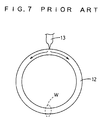
- Such a cage made of a synthetic resin is normally fabricated by injection molding. This is now described in detail by referring to Fig. 7.
- An annular cavity 12 conforming to the profile of a molded cage is formed in a die.
- a molten synthetic resin is poured into the cavity 12 from a gate 13.
- the poured synthetic resin separates into two streams flowing to the left and to the right, respectively, inside the cavity 12. These two streams meet at the opposite side of the gate 13 and recombine into one stream.
- the resinous material poured from the gate 13 as described above moves a relatively long distance until the two streams meet at the opposite side of the gate 13, the molten resinous material cools down as the two streams go toward the meeting point. If the two cooled streams meet, a weld W weaker than other portions is formed at the meeting point. In the cage of the synthetic resin including this weld, it tends to incur breakage in use. Therefore, if the meeting point of the two streams of the poured resinous material is designed to form a thin-walled portion, the decreased cross section is combined with the weld, thus resulting in a still lower strength.
- reinforcing materials such as glass fibers, carbon fibers, or metal fibers may be added.
- the added fibers disturb the orientation of the fibers at the meeting portion W of the two streams in the cage of synthetic resin. Again, the strength tends to decrease at this meeting portion W.
- One method free of this drawback is to provide plural gates circumferentially spaced around the cavity. Streams of the synthetic resin poured from the gates move a short distance to the meeting points. Thus, the streams of the poured material meet such that the temperature is hardly lowered. This increases the strength of the meeting points.
- the gates may be more widely spaced from each other circumferentially.
- the poured resinous material flows a relatively long distance. Again, there arises the possibility that welds which might have insufficient strength are formed.
- a die used to mold a cage out of a synthetic resin the cage having a cylindrical body.
- the die comprises die members having parting surfaces abutting against each other to form a mold cavity conforming to the profile of the body of the cage.
- at least one gate and a resin reservoir are formed along one parting surface outside the cavity.
- the gate and reservoir are in communication with the cavity.
- At least one gate described above is one located around the cavity.
- the resin reservoir and the gate are positioned in a diametrically opposite relation.
- the resin reservoir is smaller in volume than the cavity.
- the resin reservoir is in communication with the cavity through a narrow passageway.
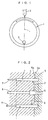
- a molding die according to a first preferred embodiment of the invention is now described by referring to Figs. 1 and 2.
- the die is composed of a pair of die members 4 and 5 having parting surfaces 4a and 5a, respectively, abutting against each other to form an annular mold cavity 1 therebetween.
- This cavity conforms to the profile of the body 10 of a cage (Fig. 6) to be molded.
- the abutting parting surfaces form a gate 2 and a resin reservoir 3.
- a synthetic resin is injected into the cavity 1 through the gate 2.
- the reservoir 3 allows meeting streams of the resinous material to be stored outside the cavity 1.
- the molding die according to the first embodiment of the invention has only one gate 2, which is located at one circumferential position on the cavity 1.
- the resin reservoir 3 is placed at the meeting point of the streams of the resinous material inside the cavity 1.
- the reservoir 3 is located on a diametrical line L passing through the center of the cavity 1 and through the opening of the gate 2. Also, the reservoir 3 is on the opposite side of the gate 2.
- the resin reservoir 3 is smaller in internal volume than the cavity 1 and in communication with the cavity 1 by way of a narrow passageway.
- the gate 2 is outside the cavity 1, while the resin reservoir 3 is inside the cavity 1.
- the gate 2 and the resin reservoir 3 may be formed inside the cavity 1 and along the parting surfaces 4a and 5a of the die members 4 and 5, respectively.
- the gate 2 and the resin reservoir 3 may be formed outside the cavity 1 in a manner not illustrated.
- the die further includes a sprue runner 6 and ejector pins 7, 8. The sprue runner 6 is in communication with the gate 2.
- a retainer or cage molded using the die according to the first embodiment of the invention, is a cage for a roller bearing
- the openings of the gate 2 and of the resin reservoir 3 are preferably formed inside the cavity 1 and in a thick-walled portion between pockets.
- the cage fabricated through the use of the die is used for a roller bearing such as a cylindrical roller or needle roller
- the openings of the gate 2 and of the resin reservoir 3 may be formed either in a pillar portion between pockets or in an annular portion provided the gate 2 and the reservoir 3 are outside the cavity 1.
- a molten synthetic resin is poured into the cavity 1 from the gate 2.
- the poured material separates into two streams flowing in opposite directions inside the cavity 1 as indicated by the arrows and subsequently meet at the resin reservoir 3 located on the opposite side of the gate 2.
- the gate may be a side gate, pin gate, or other gate. The gate can produce the same advantages, whether the gate is located inside or outside the cage or in an end surface. In the first embodiment of the invention, the die uses one gate. Examples of gates using plural gates are given below.
- these gates are normally circumferentially regularly spaced from each other around the cavity.
- the two streams of the resinous material injected into the cavity meet at the midway point of each region between the successive gates. Therefore, there exist plural meeting points of the streams in these regions. Every meeting point is provided with a resin reservoir similar to that of the first embodiment of the invention.
- the resin reservoirs are as many as the gates. Since the resinous masses formed in the resin reservoirs are discarded similarly to the sprue runner, if the number of the resin reservoirs is increased, the amount of wasted resinous material will increase.
- Second through fourth embodiments of the present invention given below use dies each having plural gates.
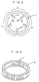
- FIG. 3 A die used to mold a cage out of a synthetic resin in accordance with the second preferred embodiment of the invention is now described by referring to Fig. 3.
- two gates 2A and 2B are formed and circumferentially spaced from each other around a mold cavity 1 formed by the die. It is to be noted that these gates 2A and 2B are not uniformly circumferentially spaced around the cavity.
- the two gates 2A and 2B form a major circumferential region dl and a minor circumferential region d2. That is, d1 > d2.
- the streams of the resinous material poured into the cavity 1 from the gates 2A and 2B meet at the midway points in the two regions d1 and d2.
- one resin reservoir 3 is formed at the meeting point of the streams in the major circumferential region d1.
- the synthetic resin injected from the gates 2A and 2B separates into two opposite streams from the injection position.
- the streams of the material meet at the midway points in the circumferential regions d1 and d2.
- the two streams of the injected material move a long distance until they meet. Therefore, the front-end portions of the streams tend to suffer from large temperature drops.
- the resin reservoir 3 is formed at the meeting point in this major circumferential region d1. Thus, the front-end portions of the streams meet and go out of the cavity 1 into the resin reservoir 3. In consequence, no weld forms unlike in the prior art technique.
- FIG. 4 there is shown a die used to mold a cage out of a synthetic resin in accordance with the third preferred embodiment.
- Three gates 2A, 2B, and 2C are formed on a mold cavity 1 in the die and circumferentially spaced from each other.
- a major circumferential region d1 is formed between the gates 2A and 2C.
- Minor circumferential regions d2 and d3 are formed between the gates 2A and 2B and between the gates 2B and 2C, respectively.
- One resin reservoir 3 is formed at the meeting point located at the midway point in the major circumferential region d1.
- the streams flow only limited distance until they meet. Therefore, in these minor regions, the streams of the injected synthetic resin quickly meet with almost no temperature drop. Hence, the bonding strength of the meeting points is increased.
- the streams of the injected material move a relatively long distance until they meet. Therefore, the front-end portions of the streams tend to suffer from temperature drop.
- the resin reservoir 3 formed at the meeting point causes the front-end portions of the streams to meet and enter the reservoir 3 from the cavity 1. For this reason, no weld appears unlike in the prior art technique.
- this third embodiment there exists only one resin reservoir in the same way as in the first and second embodiments. Consequently, only a limited amount of resin is wasted.
- FIG. 5 there is shown a molding die according to the fourth preferred embodiment of the invention.
- Major circumferential regions d1 and d2 are formed between the gates 2A and 2C and between the gates 2B and 2C, respectively.
- a minor circumferential region d3 is formed between the gates 2A and 2B. (d1, d2 > d3)
- Resin reservoirs 3B and 3A are formed at the meeting points in the two major circumferential regions d1 and d2, respectively.
- the injected synthetic resin behaves in the major and minor circumferential regions in the same way as in the third embodiment. Therefore, description of the synthetic resin is omitted here. In this embodiment, a great drop in the strength of the meeting points of the streams of the molten material and generation of welds can be prevented.
- the two resin reservoirs 3A and 3B are provided and so the amount of resin wasted is somewhat larger than in the first through third embodiments.
- this embodiment is especially adapted for the fabrication of a large cage on which gates cannot be closely spaced from each other.
- one of plural circumferential regions formed between the gates is so short that a large strength drop is not induced.
- resin reservoirs are formed at meeting points of streams of the injected resinous material. Even in this case, the number of the resin reservoirs should be reduced to a minimum to decrease the amount of wasted resin.
Landscapes
- Engineering & Computer Science (AREA)
- General Engineering & Computer Science (AREA)
- Mechanical Engineering (AREA)
- Manufacturing & Machinery (AREA)
- Moulds For Moulding Plastics Or The Like (AREA)
- Rolling Contact Bearings (AREA)
Applications Claiming Priority (3)
| Application Number | Priority Date | Filing Date | Title |
|---|---|---|---|
| JP12838697 | 1997-05-19 | ||
| JP12838697A JP3666536B2 (ja) | 1997-05-19 | 1997-05-19 | 合成樹脂製保持器の製造方法 |
| JP128386/97 | 1997-05-19 |
Publications (2)
| Publication Number | Publication Date |
|---|---|
| EP0879687A1 true EP0879687A1 (fr) | 1998-11-25 |
| EP0879687B1 EP0879687B1 (fr) | 2003-10-08 |
Family
ID=14983540
Family Applications (1)
| Application Number | Title | Priority Date | Filing Date |
|---|---|---|---|
| EP98101236A Expired - Lifetime EP0879687B1 (fr) | 1997-05-19 | 1998-01-24 | Moules et procédé pour le moulage d'une cage en résine synthétique |
Country Status (4)
| Country | Link |
|---|---|
| US (1) | US5948340A (fr) |
| EP (1) | EP0879687B1 (fr) |
| JP (1) | JP3666536B2 (fr) |
| DE (1) | DE69818742T2 (fr) |
Cited By (5)
| Publication number | Priority date | Publication date | Assignee | Title |
|---|---|---|---|---|
| KR100324218B1 (ko) * | 1999-07-08 | 2002-02-16 | 이종석 | 사출성형용 금형 |
| WO2011124389A1 (fr) * | 2010-04-10 | 2011-10-13 | Sensus Spectrum Llc | Procédé de fabrication de pièces moulées annulaires en matière plastique chargées en traction ou en compression |
| EP2664434A1 (fr) * | 2012-04-17 | 2013-11-20 | D.W. Plastics NV | Procédé de moulage par injection pour former une caisse à bouteilles, caisse à bouteilles et appareil correspondant permettant d'obtenir cette caisse à bouteilles |
| US9718226B2 (en) | 2011-04-19 | 2017-08-01 | Suzuki Motor Corporation | Method of injection molding |
| CN107428048A (zh) * | 2015-03-13 | 2017-12-01 | 日本精工株式会社 | 轴承用保持器的制造方法 |
Families Citing this family (30)
| Publication number | Priority date | Publication date | Assignee | Title |
|---|---|---|---|---|
| DE10360290B4 (de) * | 2003-12-20 | 2010-07-29 | Schaeffler Technologies Gmbh & Co. Kg | Kunststoffummantelte Rolle, insbesondere Spannrolle für einen Riementrieb |
| US7789628B2 (en) * | 2004-04-26 | 2010-09-07 | Borgwarner Inc. | Plastic fans having improved fan ring weld line strength |
| US7168922B2 (en) * | 2004-04-26 | 2007-01-30 | Borgwarner Inc. | Plastic fans having improved fan ring weld line strength |
| JP2006205580A (ja) * | 2005-01-28 | 2006-08-10 | Nishikawa Kasei Co Ltd | 樹脂製リング形状品及びその射出成形方法 |
| JP4637598B2 (ja) * | 2005-01-31 | 2011-02-23 | ダイキョーニシカワ株式会社 | 樹脂製リング形状品及びその射出成形方法 |
| JP5102964B2 (ja) * | 2006-03-10 | 2012-12-19 | Ntn株式会社 | 樹脂製保持器および軸受 |
| DE102007061589B4 (de) * | 2007-01-29 | 2017-06-22 | Nsk Ltd. | Kugellager und Halterungskonstruktion |
| US20090238914A1 (en) * | 2008-03-18 | 2009-09-24 | Cheng Uei Precision Industry Co., Ltd. | Feed mechanism of mold |
| JP5388277B2 (ja) | 2009-02-20 | 2014-01-15 | Ntn株式会社 | 保持器、転がり軸受、保持器の製造方法および射出成形用の型 |
| JP5428839B2 (ja) * | 2009-04-17 | 2014-02-26 | 日本精工株式会社 | 合成樹脂製保持器及びその製造方法、並びに転がり軸受 |
| JP5595780B2 (ja) * | 2010-04-19 | 2014-09-24 | Ntn株式会社 | 保持器 |
| JP5588214B2 (ja) * | 2010-04-19 | 2014-09-10 | Ntn株式会社 | 転がり軸受 |
| CN102792040B (zh) * | 2010-03-10 | 2016-03-23 | Ntn株式会社 | 保持器及滚动轴承 |
| DE102010014487A1 (de) * | 2010-04-10 | 2011-10-13 | Sensus Spectrum Llc | Verfahren zum Herstellen von ringförmigen, zug- oder druckbelasteten Formkörpern aus Kunststoff |
| JP4669570B1 (ja) * | 2010-06-02 | 2011-04-13 | 工立化成株式会社 | シール部材を備えた筐体の製造方法 |
| JP5636868B2 (ja) * | 2010-10-20 | 2014-12-10 | 日本精工株式会社 | 合成樹脂製保持器 |
| JP2012092862A (ja) * | 2010-10-25 | 2012-05-17 | Nsk Ltd | 合成樹脂製保持器及びその製造方法、並びに転がり軸受 |
| JP5660943B2 (ja) * | 2011-03-16 | 2015-01-28 | 東洋ゴム工業株式会社 | 金型装置 |
| JP5928122B2 (ja) * | 2012-04-20 | 2016-06-01 | 日本精工株式会社 | 射出成形用金型及び樹脂製保持器の製造方法 |
| JP5641098B2 (ja) * | 2013-06-11 | 2014-12-17 | 日本精工株式会社 | 合成樹脂製保持器の製造方法 |
| AT514828B1 (de) * | 2013-09-24 | 2015-06-15 | Hoerbiger Kompressortech Hold | Verfahren und Form zur Herstellung von Dichtplatten im Spritzguss sowie entsprechend hergestellte Dichtplatten |
| JP6396102B2 (ja) * | 2014-07-15 | 2018-09-26 | 株式会社エンプラス | 筒状品の射出成形金型及び筒状品の射出成形方法 |
| JP5850111B2 (ja) * | 2014-09-01 | 2016-02-03 | 日本精工株式会社 | 合成樹脂製保持器の製造方法 |
| JP2017118636A (ja) * | 2015-12-22 | 2017-06-29 | アスモ株式会社 | ランデル型ロータ用の補助磁石の製造方法 |
| KR20170089356A (ko) | 2016-01-26 | 2017-08-03 | 엘지전자 주식회사 | 사출성형을 위한 금형조립체 |
| EP3418024B1 (fr) * | 2016-02-19 | 2020-02-05 | NSK Ltd. | Cage de roulement et son procédé de fabrication |
| JP6575672B2 (ja) * | 2016-02-26 | 2019-09-18 | 日本精工株式会社 | 軸受用保持器の製造方法、及び軸受用保持器 |
| DE102020210648A1 (de) | 2020-08-21 | 2022-02-24 | Brose Fahrzeugteile SE & Co. Kommanditgesellschaft, Würzburg | Verfahren zur Herstellung eines Spritzgussteils |
| JP7312159B2 (ja) * | 2020-12-23 | 2023-07-20 | 三菱電線工業株式会社 | 成形型 |
| WO2024171321A1 (fr) * | 2023-02-15 | 2024-08-22 | 株式会社ジェイテクト | Dispositif de retenue, palier à roulement et procédé de moulage de dispositif de retenue |
Citations (5)
| Publication number | Priority date | Publication date | Assignee | Title |
|---|---|---|---|---|
| GB465234A (en) * | 1935-07-02 | 1937-05-04 | Celluloid Corp | Improvements in the moulding of organic materials |
| FR1351829A (fr) * | 1963-03-20 | 1964-02-07 | Schaeffler Ohg Industriewerk | Cage de roulement fabriquée en matière synthétique par injection |
| DE3718693A1 (de) * | 1987-06-04 | 1988-12-22 | Schaeffler Waelzlager Kg | Buchsenfoermiges spritzguss-bauteil, insbesondere waelzlagerkaefig |
| EP0508732A2 (fr) * | 1991-04-09 | 1992-10-14 | Polyplastics Co. Ltd. | Procédé d'injection |
| EP0573232A1 (fr) * | 1992-06-05 | 1993-12-08 | Polyplastics Co. Ltd. | Procédé de moulage par injection, moule d'injection et article moulé par injection |
Family Cites Families (8)
| Publication number | Priority date | Publication date | Assignee | Title |
|---|---|---|---|---|
| US4333899A (en) * | 1979-12-03 | 1982-06-08 | The Goodyear Tire & Rubber Company | Method and apparatus for molding a tire |
| DE3134249A1 (de) * | 1981-08-29 | 1983-03-17 | Bayer Ag, 5090 Leverkusen | Kunststoffrad |
| DE3339356A1 (de) * | 1983-10-29 | 1985-06-27 | SKF GmbH, 8720 Schweinfurt | Verfahren und vorrichtung zur herstellung von rollen |
| JPH0225962Y2 (fr) * | 1984-11-12 | 1990-07-16 | ||
| JPS6444927A (en) * | 1987-08-13 | 1989-02-17 | Oki Electric Ind Co Ltd | Resist pattern forming method |
| US5288451A (en) * | 1988-07-18 | 1994-02-22 | Husky Injection Molding Systems Ltd. | Process and apparatus for direct gating injection molding |
| DE69122178T2 (de) * | 1990-06-21 | 1997-01-30 | Fuji Photo Film Co Ltd | Magnetplattenkassette und Verfahren zu dessen Herstellung |
| JPH0796154B2 (ja) * | 1991-05-24 | 1995-10-18 | 有限会社山崎工作所 | 鋳造用金型 |
-
1997
- 1997-05-19 JP JP12838697A patent/JP3666536B2/ja not_active Expired - Fee Related
-
1998
- 1998-01-24 DE DE69818742T patent/DE69818742T2/de not_active Expired - Lifetime
- 1998-01-24 EP EP98101236A patent/EP0879687B1/fr not_active Expired - Lifetime
- 1998-01-27 US US09/014,382 patent/US5948340A/en not_active Expired - Lifetime
Patent Citations (5)
| Publication number | Priority date | Publication date | Assignee | Title |
|---|---|---|---|---|
| GB465234A (en) * | 1935-07-02 | 1937-05-04 | Celluloid Corp | Improvements in the moulding of organic materials |
| FR1351829A (fr) * | 1963-03-20 | 1964-02-07 | Schaeffler Ohg Industriewerk | Cage de roulement fabriquée en matière synthétique par injection |
| DE3718693A1 (de) * | 1987-06-04 | 1988-12-22 | Schaeffler Waelzlager Kg | Buchsenfoermiges spritzguss-bauteil, insbesondere waelzlagerkaefig |
| EP0508732A2 (fr) * | 1991-04-09 | 1992-10-14 | Polyplastics Co. Ltd. | Procédé d'injection |
| EP0573232A1 (fr) * | 1992-06-05 | 1993-12-08 | Polyplastics Co. Ltd. | Procédé de moulage par injection, moule d'injection et article moulé par injection |
Cited By (9)
| Publication number | Priority date | Publication date | Assignee | Title |
|---|---|---|---|---|
| KR100324218B1 (ko) * | 1999-07-08 | 2002-02-16 | 이종석 | 사출성형용 금형 |
| WO2011124389A1 (fr) * | 2010-04-10 | 2011-10-13 | Sensus Spectrum Llc | Procédé de fabrication de pièces moulées annulaires en matière plastique chargées en traction ou en compression |
| CN103140340A (zh) * | 2010-04-10 | 2013-06-05 | 传感频谱有限责任公司 | 由塑料制造环形的承受拉负荷或压负荷的模塑件的方法 |
| RU2531194C2 (ru) * | 2010-04-10 | 2014-10-20 | СЕНСУС СПЕКТРУМ ЭлЭлСи | Способ изготовления кольцеобразных формованных изделий из пластмассы, устойчивых к нагрузкам на растяжение или сжатие |
| CN103140340B (zh) * | 2010-04-10 | 2015-10-21 | 传感频谱有限责任公司 | 由塑料制造环形的承受拉负荷或压负荷的模塑件的方法 |
| US9718226B2 (en) | 2011-04-19 | 2017-08-01 | Suzuki Motor Corporation | Method of injection molding |
| EP2664434A1 (fr) * | 2012-04-17 | 2013-11-20 | D.W. Plastics NV | Procédé de moulage par injection pour former une caisse à bouteilles, caisse à bouteilles et appareil correspondant permettant d'obtenir cette caisse à bouteilles |
| CN107428048A (zh) * | 2015-03-13 | 2017-12-01 | 日本精工株式会社 | 轴承用保持器的制造方法 |
| EP3257651A4 (fr) * | 2015-03-13 | 2018-05-23 | NSK Ltd. | Procédé de fabrication de support de palier |
Also Published As
| Publication number | Publication date |
|---|---|
| EP0879687B1 (fr) | 2003-10-08 |
| DE69818742D1 (de) | 2003-11-13 |
| US5948340A (en) | 1999-09-07 |
| DE69818742T2 (de) | 2004-07-29 |
| JP3666536B2 (ja) | 2005-06-29 |
| JPH10318263A (ja) | 1998-12-02 |
Similar Documents
| Publication | Publication Date | Title |
|---|---|---|
| US5948340A (en) | Die and method for molding cage out of synthetic resin | |
| US4668209A (en) | Plastic-surrounded bearing | |
| JPS5976230A (ja) | 中空のプラスチック成形品の射出成形方法 | |
| JP2006070926A (ja) | 円錐ころ軸受用保持器 | |
| CN108779804B (zh) | 轴承用保持架的制造方法 | |
| US5874116A (en) | Injection molding apparatus having a divided degassing pin | |
| JP6772587B2 (ja) | 合成樹脂製保持器の製造方法及び合成樹脂製保持器 | |
| JP2002005176A (ja) | ころ軸受用合成樹脂保持器およびその製造方法 | |
| US20090011168A1 (en) | Circular resin-molded product having circular center hole and method and apparatus for molding the same | |
| JP6299529B2 (ja) | 軸受用保持器、及びその製造方法 | |
| JPH08197649A (ja) | 合成樹脂製保持器の製造方法 | |
| US5458842A (en) | Method for molding steering wheels | |
| JP2019126959A (ja) | 軸受用保持器の製造方法 | |
| JPH0791525A (ja) | 合成樹脂製プーリ | |
| JP2009143104A (ja) | 成形型及び成形方法 | |
| JP2020076506A (ja) | 転がり軸受用合成樹脂製保持器 | |
| JP3163873B2 (ja) | 複合製品の製造方法及びその製造用金型 | |
| JP4269530B2 (ja) | 樹脂プーリ付き軸受およびその製造方法 | |
| JP6471813B2 (ja) | 軸受用保持器 | |
| JPH09264402A (ja) | 合成樹脂製プーリ | |
| JP6451190B2 (ja) | 軸受用保持器の製造方法 | |
| JP5928122B2 (ja) | 射出成形用金型及び樹脂製保持器の製造方法 | |
| JP6658841B2 (ja) | 軸受用保持器 | |
| JP6658053B2 (ja) | 転がり軸受用合成樹脂製保持器 | |
| KR200151951Y1 (ko) | 사출성형물의 런너 변형을 방지하는 금형 |
Legal Events
| Date | Code | Title | Description |
|---|---|---|---|
| PUAI | Public reference made under article 153(3) epc to a published international application that has entered the european phase |
Free format text: ORIGINAL CODE: 0009012 |
|
| AK | Designated contracting states |
Kind code of ref document: A1 Designated state(s): DE FR GB IT |
|
| AX | Request for extension of the european patent |
Free format text: AL;LT;LV;MK;RO;SI |
|
| 17P | Request for examination filed |
Effective date: 19990112 |
|
| AKX | Designation fees paid |
Free format text: DE FR GB IT |
|
| 17Q | First examination report despatched |
Effective date: 20010129 |
|
| RTI1 | Title (correction) |
Free format text: DIES AND METHOD FOR MOLDING CAGE OUT OF SYNTHETIC RESIN |
|
| GRAH | Despatch of communication of intention to grant a patent |
Free format text: ORIGINAL CODE: EPIDOS IGRA |
|
| RAP1 | Party data changed (applicant data changed or rights of an application transferred) |
Owner name: KOYO SEIKO CO., LTD. |
|
| GRAS | Grant fee paid |
Free format text: ORIGINAL CODE: EPIDOSNIGR3 |
|
| GRAA | (expected) grant |
Free format text: ORIGINAL CODE: 0009210 |
|
| AK | Designated contracting states |
Kind code of ref document: B1 Designated state(s): DE FR GB IT |
|
| REG | Reference to a national code |
Ref country code: GB Ref legal event code: FG4D |
|
| REF | Corresponds to: |
Ref document number: 69818742 Country of ref document: DE Date of ref document: 20031113 Kind code of ref document: P |
|
| ET | Fr: translation filed | ||
| PLBI | Opposition filed |
Free format text: ORIGINAL CODE: 0009260 |
|
| PLAX | Notice of opposition and request to file observation + time limit sent |
Free format text: ORIGINAL CODE: EPIDOSNOBS2 |
|
| 26 | Opposition filed |
Opponent name: DR. M. GOSDIN Effective date: 20040626 |
|
| PLBB | Reply of patent proprietor to notice(s) of opposition received |
Free format text: ORIGINAL CODE: EPIDOSNOBS3 |
|
| PLCK | Communication despatched that opposition was rejected |
Free format text: ORIGINAL CODE: EPIDOSNREJ1 |
|
| PLBN | Opposition rejected |
Free format text: ORIGINAL CODE: 0009273 |
|
| STAA | Information on the status of an ep patent application or granted ep patent |
Free format text: STATUS: OPPOSITION REJECTED |
|
| 27O | Opposition rejected |
Effective date: 20051229 |
|
| PGFP | Annual fee paid to national office [announced via postgrant information from national office to epo] |
Ref country code: IT Payment date: 20080130 Year of fee payment: 11 Ref country code: GB Payment date: 20080123 Year of fee payment: 11 |
|
| GBPC | Gb: european patent ceased through non-payment of renewal fee |
Effective date: 20090124 |
|
| PG25 | Lapsed in a contracting state [announced via postgrant information from national office to epo] |
Ref country code: GB Free format text: LAPSE BECAUSE OF NON-PAYMENT OF DUE FEES Effective date: 20090124 |
|
| PG25 | Lapsed in a contracting state [announced via postgrant information from national office to epo] |
Ref country code: IT Free format text: LAPSE BECAUSE OF NON-PAYMENT OF DUE FEES Effective date: 20090124 |
|
| REG | Reference to a national code |
Ref country code: FR Ref legal event code: PLFP Year of fee payment: 19 |
|
| REG | Reference to a national code |
Ref country code: FR Ref legal event code: PLFP Year of fee payment: 20 |
|
| PGFP | Annual fee paid to national office [announced via postgrant information from national office to epo] |
Ref country code: FR Payment date: 20161215 Year of fee payment: 20 |
|
| PGFP | Annual fee paid to national office [announced via postgrant information from national office to epo] |
Ref country code: DE Payment date: 20170117 Year of fee payment: 20 |
|
| REG | Reference to a national code |
Ref country code: DE Ref legal event code: R071 Ref document number: 69818742 Country of ref document: DE |