EP0879691A2 - Giessanlage zur Bildung einer Harzmembrane - Google Patents
Giessanlage zur Bildung einer Harzmembrane Download PDFInfo
- Publication number
- EP0879691A2 EP0879691A2 EP98106789A EP98106789A EP0879691A2 EP 0879691 A2 EP0879691 A2 EP 0879691A2 EP 98106789 A EP98106789 A EP 98106789A EP 98106789 A EP98106789 A EP 98106789A EP 0879691 A2 EP0879691 A2 EP 0879691A2
- Authority
- EP
- European Patent Office
- Prior art keywords
- suction chamber
- membrane
- die
- resin
- casting apparatus
- Prior art date
- Legal status (The legal status is an assumption and is not a legal conclusion. Google has not performed a legal analysis and makes no representation as to the accuracy of the status listed.)
- Granted
Links
Images











Classifications
-
- B—PERFORMING OPERATIONS; TRANSPORTING
- B29—WORKING OF PLASTICS; WORKING OF SUBSTANCES IN A PLASTIC STATE IN GENERAL
- B29C—SHAPING OR JOINING OF PLASTICS; SHAPING OF MATERIAL IN A PLASTIC STATE, NOT OTHERWISE PROVIDED FOR; AFTER-TREATMENT OF THE SHAPED PRODUCTS, e.g. REPAIRING
- B29C48/00—Extrusion moulding, i.e. expressing the moulding material through a die or nozzle which imparts the desired form; Apparatus therefor
- B29C48/25—Component parts, details or accessories; Auxiliary operations
- B29C48/88—Thermal treatment of the stream of extruded material, e.g. cooling
- B29C48/911—Cooling
- B29C48/9135—Cooling of flat articles, e.g. using specially adapted supporting means
- B29C48/915—Cooling of flat articles, e.g. using specially adapted supporting means with means for improving the adhesion to the supporting means
- B29C48/916—Cooling of flat articles, e.g. using specially adapted supporting means with means for improving the adhesion to the supporting means using vacuum
-
- B—PERFORMING OPERATIONS; TRANSPORTING
- B29—WORKING OF PLASTICS; WORKING OF SUBSTANCES IN A PLASTIC STATE IN GENERAL
- B29C—SHAPING OR JOINING OF PLASTICS; SHAPING OF MATERIAL IN A PLASTIC STATE, NOT OTHERWISE PROVIDED FOR; AFTER-TREATMENT OF THE SHAPED PRODUCTS, e.g. REPAIRING
- B29C48/00—Extrusion moulding, i.e. expressing the moulding material through a die or nozzle which imparts the desired form; Apparatus therefor
- B29C48/03—Extrusion moulding, i.e. expressing the moulding material through a die or nozzle which imparts the desired form; Apparatus therefor characterised by the shape of the extruded material at extrusion
- B29C48/07—Flat, e.g. panels
- B29C48/08—Flat, e.g. panels flexible, e.g. films
-
- B—PERFORMING OPERATIONS; TRANSPORTING
- B29—WORKING OF PLASTICS; WORKING OF SUBSTANCES IN A PLASTIC STATE IN GENERAL
- B29C—SHAPING OR JOINING OF PLASTICS; SHAPING OF MATERIAL IN A PLASTIC STATE, NOT OTHERWISE PROVIDED FOR; AFTER-TREATMENT OF THE SHAPED PRODUCTS, e.g. REPAIRING
- B29C48/00—Extrusion moulding, i.e. expressing the moulding material through a die or nozzle which imparts the desired form; Apparatus therefor
- B29C48/25—Component parts, details or accessories; Auxiliary operations
- B29C48/88—Thermal treatment of the stream of extruded material, e.g. cooling
- B29C48/911—Cooling
- B29C48/9135—Cooling of flat articles, e.g. using specially adapted supporting means
- B29C48/914—Cooling drums
-
- Y—GENERAL TAGGING OF NEW TECHNOLOGICAL DEVELOPMENTS; GENERAL TAGGING OF CROSS-SECTIONAL TECHNOLOGIES SPANNING OVER SEVERAL SECTIONS OF THE IPC; TECHNICAL SUBJECTS COVERED BY FORMER USPC CROSS-REFERENCE ART COLLECTIONS [XRACs] AND DIGESTS
- Y10—TECHNICAL SUBJECTS COVERED BY FORMER USPC
- Y10S—TECHNICAL SUBJECTS COVERED BY FORMER USPC CROSS-REFERENCE ART COLLECTIONS [XRACs] AND DIGESTS
- Y10S425/00—Plastic article or earthenware shaping or treating: apparatus
- Y10S425/016—Extrude and mold
Definitions
- the present invention is for the purpose of forming a film-like or sheet-like resin-made membrane (signifying a thin-film), and relates to a resin-made membrane formation casting apparatus suitably used, for example, as a biaxial oriented film machine, a non-oriented film machine, a sheet machine, and others.
- Figs. 31 and 32 are respectively a side elevational view and a front elevational view each illustratively showing a prior resin-made membrane formation casting apparatus.
- Fig. 32 shows only one end portion side of the prior apparatus in its width direction, the other end portion side is constructed in a similar way.
- the prior apparatus is equipped with a T die 101 for extruding a molten resin from an extruding machine (not shown) into a film-like or sheet-like membrane 102, a casting roll (cooling roll) 103 for receiving the membrane 102 extruded from the T die 101 on its outer circumferential surface to cool and deliver the membrane 102, and a suction chamber (vacuum box) 104 for stably making the membrane 102 come closely into contact with the surface of the casting roll 103.
- a T die 101 for extruding a molten resin from an extruding machine (not shown) into a film-like or sheet-like membrane 102
- a casting roll (cooling roll) 103 for receiving the membrane 102 extruded from the T die 101 on its outer circumferential surface to cool and deliver the membrane 102
- a suction chamber (vacuum box) 104 for stably making the membrane 102 come closely into contact with the surface of the casting roll 103.
- the casting roll 103 is supported by a roll supporting shaft 106 to be rotatable with respect to a side frame 107.
- the suction chamber 104 is fixedly secured on one side surface of the T die 101. Further, a vacuum pump 105 is in a coupled relation to the suction chamber 104 so that, when this vacuum pump 105 is placed into operation, the air between the membrane 102 and the casting roll 103 is sucked through an opening section 104a of the suction chamber 104.
- the opening section 104a is made throughout the overall width of the membrane 102 in the proximity of a portion where the membrane 102 starts to come closely into contact with the outer circumferential surface of the casting roll 103. Further, a seal gap 104b is defined between the suction chamber 104 and the casting roll 103. The dimension of the seal gap 104b is set to ensure a required suction force (pressure reduction level) at the close contact section between the membrane 102 and the casting roll 103 concurrently with allowing the rotation of the casting roll 103.
- reference numeral 108 represents wheels to be used when shifting this apparatus.
- the resin molten by the non-shown extruding machine passes through the T die 101 to be extruded into a film-like or sheet-like membrane 102 which in turn, is placed on the outer circumferential surface of the casting roll 103 to be cooled for formation.
- the air within the suction chamber 104 is sucked by the vacuum pump 105 so that the air in the close contact section between the membrane 102 and the casting roll 103 is sucked through the opening section 104a of the suction chamber 104.
- that close contact section is pressure-reduced to discharge the air taken in between the membrane 102 and the casting roll 103, with the result that the membrane 102 made of the molten resin can stably be brought into contact with the casting roll 103.
- the seal gap 104b between the suction chamber 104 and the casting roll 103 results in enlargement to make it difficult to obtain a necessary suction force, so that the removal of the air taken in between the membrane 102 and the casting roll 103 becomes impossible, with the result that it is impossible to stably make the membrane 102 come closely into contact with the casting roll 103.
- the configuration of the vacuum space defined by the membrane-like molten resin immediately after being discharged from the T die 101, the outer circumferential surface of the casting roll 103 and the tip portion of the suction chamber 104, or the occurrence or non-occurrence of the flow of the outside air into that vacuum space has influence on the stably closely contacting condition of the membrane 102 with the casting roll 103 in accordance with the conditions such as the kind of resin being a material, the resin viscosity when molten, the thickness of the membrane 102 and the formation speed.
- the outside-air flow situation into the vacuum space affects the stably close contact of the membrane 102 with the casting roll 103.
- Fig. 33 shows an outside-air inflow situation (the dotted arrows denote air flows) in a cross section taken along a line S-S of Fig. 31, and as shown in Fig. 33, the membrane 102 vibrates (swings) or is brought into the interior of the suction chamber 104 due to the occurrence of the dynamic pressure at a portion designated at B2 and the eddy caused by the suction at a portion depicted at B1, which hinders the speed-up of the membrane formation.
- the present invention has been developed with a view to eliminating the above-mentioned problems, and it is therefore an object of this invention to provide a casting apparatus for resin-made membrane formation which is capable of accomplishing the stable pressure reduction by a suction chamber without depending upon the dimension of the interval between a die and a cooling roll and of appropriately setting the interval between the die and the cooling roll irrespective of any kind of resin so that the necessary membrane characteristic is securable to improve the quality of a resin-made membrane.
- a casting apparatus for resin-made membrane formation comprises a die for extruding a molten resin into a membrane, a cooling roll for receiving the membrane extruded from the die on its outer circumferential surface to deliver it while cooling, and a suction chamber for sucking air between the membrane and the cooling roll so that the membrane is brought closely into contact with the surface of the cooling roll, wherein the suction chamber is disposed independently of the die and is located to define a necessary seal gap with respect to the cooling roll, and a circumferentially moving mechanism is further provided to move the suction chamber along a circumferential direction of the cooling roll in a state of maintaining the necessary seal gap.
- the suction chamber is separated from the die and is provided independently of the die, and the suction chamber is designed to be moved along the circumferential direction of the cooling roll by the circumferentially moving mechanism while the necessary seal gap is maintained between the suction chamber and the cooling roll.
- the suction chamber can be moved in the circumferential direction of the cooling roll in a manner that the driving member is rotated around the rotary shaft of the cooling roll.
- the cooling roll can be shifted in the circumferential direction of the cooling roll by means of guiding the suction chamber along the guide member.
- the suction chamber can be shifted in the circumferential direction of the cooling roll in a manner that the driving member is rotated around the rotary shaft of the cooling roll and the suction chamber is guided along the guide member.
- the necessary pressure reduction level is securable, with the result that the pressure reduction of the space between the membrane and the cooling roll can stably be done by the suction chamber.
- the elastic seal member if the elastic seal member is put between the die and the suction chamber, even if the variation of the dimension of the interval between the die and the cooling roll or the position of the suction chamber takes place, the elastic seal member can close the gap between the die and the suction chamber following that variation, with the result that the airtightness of the pressure reduction space surrounded by the die, the membrane and the suction chamber is securable so that the necessary pressure reduction level is surely obtainable in that pressure reduction space.
- the elastic seal member is disposed throughout a width exceeding the overall width of the membrane and is pressed against the die with an elastic force to come into contact therewith to close the gap between the die and the suction chamber, irrespective of the variation of the position of the suction chamber, the elastic member can automatically and certainly close the interval between the suction chamber and the die, and therefore, the airtightness of the pressure reduction space surrounded by the die, the membrane and the suction chamber is securable, thereby surely providing the necessary pressure reduction level in the pressure reduction space.
- the suction chamber is movable in the circumferential and radial directions of the cooling roll in a state where the seal gap is maintainable between the suction chamber and the cooling roll and the seal gap between the suction chamber and the cooling roll is adjustable, and further, that gap can be sealed with the elastic seal member irrespective of the dimension of the interval between the die and the suction chamber.
- the interval between the die and the cooling roll can adequately be set for any kind of resin, which ensures the necessary membrane characteristic to sharply improve the quality of the resin-made membrane.
- the shielding plate capable of shielding the end portion of the suction opening section of the suction chamber or the suction nozzle made to suck the air from the end portion side direction of the suction opening section of the suction chamber, the main flow into the space defined by the membrane extruded from the die, the cooling roll and the suction chamber due to the suction is controllable, so that it is possible to suppress the vibrations (swinging) of the membrane or the introduction of the membrane into the suction chamber, with the result that the stable membrane formation is feasible for any kind of resin.
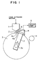
- Fig. 1 is a side elevational view illustratively showing a casting apparatus for resin-made membrane formation according to a first embodiment of the present invention, and as shown in Fig. 1, the casting apparatus according to the first embodiment is also composed of a T die (die) 1 for extruding a resin molten by an extruding machine (not shown) into a film-like or sheet-like membrane (thin-film) 2, a casting roll (cooling roll) 3 for receiving the membrane 2 extruded from the T die 1 on its outer circumferential surface to cool and deliver it, and a suction chamber 4 for sucking air between the membrane 2 and the casting roll 3 to make the membrane 2 stably come closely into contact with the surface of the casting roll 3.
- a T die die
- a casting roll (cooling roll) 3 for receiving the membrane 2 extruded from the T die 1 on its outer circumferential surface to cool and deliver it
- a suction chamber 4 for sucking air between the membrane 2 and the casting roll 3 to make the membrane 2
- the suction chamber 4 is provided independently of the T die 1. Further, the suction chamber 4 is formed along the outer circumferential surface of the casting roll 3, and a necessary seal gap 4d is defined between the suction chamber 4 and the outer circumferential surface of the casting roll 3. The dimension (interval) of this seal gap 4d is set to ensure a necessary suction force (pressure reduction level) at a close contact section between the membrane 2 and the casting roll 3 while allowing the rotation of the casting roll 3.
- a vacuum pump 5 is in communication with the suction chamber 4, and on the operation of this vacuum pump 5, the air between the membrane 2 and the casting roll 3 is sucked through an opening section 4a of the suction chamber 4. Further, the opening section 4a (suction inlet) is made throughout the overall width of the membrane 2 in the proximity of the portion where the membrane 2 starts to come closely into contact with the outer circumferential surface of the casting roll 3.
- a driving member 7 is used as a circumferentially moving mechanism designed to move the suction chamber 4 along a circumferential direction of the casting roll 3 while maintaining the necessary seal gap 4d.
- This driving member 7 is made such that its proximal side supported coaxially with a roll supporting shaft (rotary shaft) 3a of the casting roll 3 to be rotatable around the roll supporting shaft 3a (in directions of arrows A in Fig. 1) while its tip side is in a fixed relation to the suction chamber 4.
- an elastic seal body (elastic seal member) 6 is interposed between the T die 1 and the suction chamber 4, and the gap between the T die 1 and the suction chamber 4 is sealed by the effect of the elastic seal body 6.
- the resin-made membrane formation casting apparatus is constructed as mentioned above, a resin molten by the non-shown extruding machine is extruded from the T die 1 into a film-like or sheet-like membrane 2 which in turn, is taken on the outer circumferential surface of the casting roll 3 to be cooled for formation.
- the vacuum pump 5 sucks the air within the suction chamber 4, the air in the close contact section between the membrane 2 and the casting roll 3 is sucked through the opening section 4a of the suction chamber 4.
- the space close to that close-contact section is pressure-reduced to discharge the air taken in between the membrane 2 and the casting roll 3, so that the membrane 2 made of a molten resin can stably be brought into close contact with the casting roll 3.
- the suction chamber 4 is separated from the T die 1 and disposed independently of the T die 1, and through the use of the driving member 7, the suction chamber 4 is movable along the circumferential directions of the casting roll 3 in a state where the necessary seal gap 4d is maintained between the suction chamber 4 and the casting roll 3.
- the suction chamber 4 is shifted by the driving member 7 counterclockwise around the roll supporting shaft 3a to advance to a given position so that the suction inlet (opening section 4a) of the suction chamber 4 approaches the close-contact starting section between the membrane 2 and the casting roll 3, with the result that the interval between the membrane 2 and the opening section 4a of the suction chamber 4 decreases.
- the suction chamber 4 is shifted by the driving member 7 clockwise around the roll supporting shaft 3a to retreat up to a given position.
- the necessary pressure reduction level is attainable in the pressure reduction space, so that the pressure reduction in the space between the membrane 2 and the casting roll 3 is stably achievable by the suction chamber 4.
- the elastic seal body 6 is interposed between the T die 1 and the suction chamber 4, even if the interval (gap) between the T die 1 and the suction chamber 4 varies, the elastic seal member closes the gap between the T die 1 and the suction chamber 4 in accordance with the variation. Whereupon, the airtightness of the pressure reduction space surrounded by the T die 1, the membrane 2 and the suction chamber 4 is maintainable so that the necessary pressure reduction level is certainly obtainable in that pressure reduction space.
- the rotating operation of the suction chamber 4 by rotationally driving the driving member 7 around the roll supporting shaft 3a can rely on a manual operation and can be through a non-shown driving mechanism (drive motor).
- the pressure reduction in the space between the membrane 2 and the casting roll 3 is stably achievable by the suction chamber 4, and therefore, it is possible to appropriately set the interval between the T die 1 and the casting roll 3 with respect to any kind of resin, with the result that the necessary film characteristic (membrane characteristic) is securable to sharply improve the quality of the resin-made membrane (film or sheet) 2.
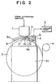
- Fig. 2 illustratively shows a casting apparatus for resin-made membrane formation according to a second embodiment of this invention.
- the casting apparatus according to the second embodiment has the substantially same construction as that of the apparatus according to the first embodiment as shown in Fig. 2, in the second embodiment, a guide member 8 is employed as a circumferentially moving mechanism made to shift a suction chamber 4 along the circumferential directions of a casting roll 3 in a state where a necessary seal gap 4d is kept.
- This guide member 8 is fitted to a side frame 8b made to rotatably support a side end portion of the casting roll 3.
- the guide member 8 has an elongated hole-like guide rail 8 a made to engage with two pins (rollers) 4c, 4c fitted onto a side surface of the suction chamber 4 to guide the suction chamber 4 along circumferential directions (in directions of arrows B in Fig. 2) of the casting roll 3.
- the structure other than the aforesaid circumferentially moving mechanism is the same as that of the first embodiment, and hence, the description thereof will be omitted.
- the suction chamber 4 is shifted counterclockwise (in the left-hand direction in Fig. 2) along the elongated hole-like guide rail 8a of the guide member 8 to advance to a given position so that the suction inlet (opening section 4a) of the suction chamber 4 approaches the close contact starting portion between the membrane 2 and the casting roll 3, thereby shortening the interval between the membrane 2 and the opening section 4a of the suction chamber 4.
- the suction chamber 4 is moved clockwise (in the right-hand direction in Fig. 2) along the elongated hole-like guide rail 8a of the guide member 8 to retreat to a given position.
- the suction chamber 4 is formed along the outer circumferential surface of the casting roll 3, although the suction chamber 4 moves along the elongated hole-like guide rail 8a of the guide member 8, the necessary seal gap 4d is always held between the suction chamber 4 and the outer circumferential surface of the casting roll 3.
- the movement of the suction chamber 4 along the guide rail 8a can manually done or conducted through the use of a driving mechanism (not shown).
- the resin-made membrane formation casting apparatus according to the second embodiment of this invention can also offer the same effects as those of the first embodiment.
- Fig. 3 illustratively shows a casting apparatus for resin-made membrane formation according to a third embodiment of this invention.
- the casting apparatus has the substantially same structure as that of the first embodiment as shown in Fig. 3, in the third embodiment, a driving member 9 and a guide member 10 are used as the circumferentially moving mechanism which moves a suction chamber 4 along circumferential directions of a casting roll 3 while keeping a necessary seal gap 4d.
- the driving member 9 is designed such that its proximal side is supported coaxially with a roll supporting shaft (rotary shaft) 3a of the casting roll 3 to be rotatable around the roll supporting shaft 3a (in directions of arrows D in Fig. 3) while the guide member 10 is attached to its tip side.
- This guide member 10 has an elongated hole-like guide rail 10a made to engage with two pins (or rollers) 4c, 4c fitted onto a side surface of the suction chamber 4 to guide the suction chamber 4 along circumferential directions of the casting roll 3 (in directions of arrows C in Fig. 3).
- the suction chamber 4 is first shifted by the driving member 9 counterclockwise around the roll supporting shaft 3a to proceed to an appropriate position for rough adjustment and the suction chamber 4 is then moved along the elongated hole-like guide rail 10a of the guide member 10 to be positioned at a given position for fine adjustment, so that the suction inlet (opening section 4a) of the suction chamber 4 is positioned in the vicinity of the close-contact starting portion between the membrane 2 and the casting roll 3.
- the rough adjustment is first made such that the suction chamber 4 is moved by the driving member 9 clockwise around the roll supporting shaft 3a to retreat to an appropriate position and subsequently the fine adjustment is made such that the suction chamber 4 is shifted along the elongated hole-like guide rail 10a of the guide member 10 to be positioned at a given position.
- the suction chamber 4 is formed along the outer circumferential surface of the casting roll 3, although the suction chamber 4 is rotated by the driving member 9 and although being shifted along the elongated hole-like guide rail 10a of the guide member 10, the necessary seal gap 4d stays between the suction chamber 4 and the outer circumferential surface of the casting roll 3.
- the rotation of the suction chamber 4 by rotationally driving the driving member 9 around the roll supporting shaft 3a can rely on a manual operation and can be through a non-shown driving mechanism (drive motor).
- the movement of the suction chamber 4 around the guide rail 10a can rely on a manual operation and can be through a non-shown driving mechanism.
- the resin-made membrane formation casting apparatus can also obtain the same effects as those of the first embodiment, and since in the third embodiment the positioning of the suction chamber 4 is made through the two steps of the rough adjustment by the driving member 9 and the fine adjustment by the guide member 10, the positioning is achievable with a high accuracy.
- the elastic seal body 6 closes the gap between the T die 1 and the suction chamber 4
- other structures are also appropriate as long as they can close the gap between the T die 1 and the suction chamber 4 while following the variation of the dimension of the gap, and in addition to an elastic body such as a rubber, bellows members or the like are also acceptable.
- Figs. 4 to 7 respectively show principal sections of a casting apparatus for resin-made membrane formation according to a fourth embodiment of this invention.
- Figs. 4 and 5 are a perspective view and a side-elevational cross-sectional view each showing a structure and fitted condition of an elastic seal member thereof
- Fig. 6 is a side-elevational cross-sectional view showing a mounted condition of the elastic member
- Fig. 7 is a side-elevational cross-sectional view showing a mounted condition of an elastic seal member different in size from the Fig. 6 member.
- the same numerals as the above-taken numerals represent the same parts, and the description thereof will be omitted.
- the suction chamber (vacuum box) represented at numeral 4 in the first to third embodiments will be designated at numeral 40, and the elastic seal body 6 will be described as being an elastic seal member 50.
- a suction chamber 40 of the casting apparatus fulfills a function similar to that of the suction chamber 4 in the first to third embodiments, and is composed of a housing 41 comprising upper walls 41a, 41b, a rear wall 41c and left- and right-hand side walls 41d, and labyrinth packings 42, 43 fixedly secured to outer-surface lower portions of the left- and right-hand side walls 41d and to the rear wall 41c, respectively.
- the labyrinth packing 43 is fixed to the left-and right-hand side walls 42d.
- a front side (left side in Figs. 5 and 6) of the suction chamber 40 is open, and a suction inlet (opening section) 40a is made between the upper wall 41a of the suction chamber 40 and an outer circumferential surface of the casting roll 3.
- the housing 41 is closed by the outer circumferential surface of the casting roll 3 from the below except the suction inlet 40a, and a suction room 40b is defined between the housing 41 and the casting roll 3.
- the labyrinth packings 42, 43 stand against the outer circumferential surface of the casting roll 3 in a state where they are in a slightly spaced relation to each other to possibly suppress the inflow of the air from below the rear wall 41c and the left- and right-hand walls 41d.
- the suction room 40b is coupled through a suction duct 60, fixedly secured to the upper wall 41b, to a vacuum pump 5 (see Figs. 1 to 3).
- the entire suction chamber 40 is rotatably supported coaxially with the casting roll 3 (around the roll supporting shaft 3a) through any one of the circumferentially moving mechanisms described with reference to Figs. 1 to 3 to be revolvable along the outer circumferential surface of the casting roll 3 while maintaining the necessary seal gap.
- the elastic seal member 50 is disposed throughout a width exceeding the overall width of the membrane 2, and as shown in Figs. 4 to 7, is made up of an elastic seal body 51 and fixtures (fitting tools) 52, 53.
- the elastic seal body 51 is made of a foaming agent such as a polyimide foam having an excellent heat resistance, a high impact resilience and a less compressive permanent strain, and formed into a semicircular bar-like configuration in cross section, with its front surface being covered with a glass cloth (made by integrally adhering an aluminium foil through an adhesive to a glass cloth) coated with an aluminium foil.
- a foaming agent such as a polyimide foam having an excellent heat resistance, a high impact resilience and a less compressive permanent strain
- This elastic seal body 51 is fixed to the suction chamber 40 in a manner that its lower portion is held between rising portions 52b, 53b of the fixtures 52, 53 in the forward and backward directions and the fixtures 52, 53 are fixedly tightened with fitting bolts 55 with respect to the upper wall 41a of the suction chamber 40.
- the elastic seal member 50 closes the gap between the T die 1 and the suction chamber 40 in a manner that the elastic seal body 51 is pressed by an elastic force to be brought into contact with the T die 1.
- the fixture 53 is disposed to be placed on the fixture 52, and in a state where elongated holes 52a made on the fixture 52 side are aligned with elongated holes 53a made on the fixture 53 side, the fitting bolts 55 are inserted through washers 54 into these elongated holes 52a, 53a and tightened with respect to the upper wall 41a of the suction chamber 40 so that the fixtures 52, 53 are fixed integrally.
- upper wall 41a side female screws to be engaged with the fitting bolts 55 are constructed as blind screws in a rear plate 41e.
- the elongated holes 52a are made for the purpose of changing the position of the fixture 53 so that elastic seal bodies 51 different in size can be fitted to the suction chamber 40. Further, the elongated holes 53a are for the purpose of adjusting the fitting position of the elastic seal member 50 to the suction chamber 40 in cooperation with the fixture 52 side elongated holes 52a.
- the elastic seal member 50 can be shifted from the position indicated with a solid line in Figs. 6 and 7 to the position indicated with a dashed line A3 in Figs. 6 and 7.
- Fig. 6 in the apparatus according to the fourth embodiment, since, for example, the membrane (film, sheet) 2 has a thin thickness and a relatively weak force suffices for sucking the membrane 2 by the suction chamber 40, the distance between the T die 1 and the casting roll 3 is shown to be short.
- Fig. 7 in the apparatus according to the fourth embodiment, since, for example, the membrane (film, sheet) 2 is thick and the force for sucking the membrane 2 by the suction chamber 40 needs to be relatively strong, the distance between the T die 1 and the casting roll 3 is shown to be long.
- the lower surface configuration of the T die 1 of the apparatus shown in Figs. 1 to 3 has a gradient to spread from a horizontal plane in the vicinity of an opening for the extrusion of the membrane 2 toward the external (right-hand side in the illustrations), in this embodiment shown in Figs. 6 and 7, the lower surface configuration of the T die 1 has two different gradients. However, the difference between these T die 1 lower surface configurations does not particularly make a sense. Further, it is also appropriate that the elastic seal member 50 is attached to the lower surface of the T die 1 and is pressed with an elastic force to be brought into contact with the upper surface side of the suction chamber 40.
- a molten resin is extruded from the T die 1 into the membrane 2 which in turn, is rolled around the casting roll 3 to be formed while cooled.
- the membrane 2 in the molten condition is pulled by the casting roll 3 to run in a direction indicated with a two-dot chain line A1 in Fig. 6 or 7, and at this time, air is taken in between the membrane 2 and the casting roll 3, thus deteriorating the quality of the membrane 2.
- the sucking operation of the suction chamber 40 produces a negative pressure on the rear side of the membrane 2 (the right-hand side in Figs. 6 and 7), and the pressure difference from the front side pressure pulls the membrane 2 backwardly so that the membrane 2 takes the standing position shown by a solid line in Figs. 6 and 7 to enlarge the entry angle of the membrane 2 into the casting roll 3.
- a partition is formed on the rear side of the membrane 2 and the air between the partition and the membrane 2 is sucked by the suction chamber 40. If this space partitioned does not has an appropriate dimension, an unstable phenomenon that the membrane 2 vibrates by the air sucked takes place. Particularly, as indicated with an arrow A2 in Fig. 6, when the passes through between the T die 1 and the suction chamber 40 to flow into the interior of the suction room 40b, the unstableness tends to occur.
- the tip portion of the suction chamber 40 is adjusted to take an optimal position where the unstable phenomenon is hard to occur, and for that adjustment, there is a need to close the gap between the T die 1 and the suction chamber 40 to prevent the formation of the air inflow passage from the external even if changing the position of the suction chamber 40.
- the elastic seal member 50 elastically deforms to automatically continue to close the gap therebetween.
- Figs. 6 and 7 the contour configuration of the elastic seal member 50 before the movement of the suction chamber 40 (the contour configuration before being pressed by the T die 1 to deform) is shown with a two-dot chain line.
- the elastic seal member 50 itself is replaced with an elastic seal member with a different size for adjustment.
- the elastic seal member 50 can certainly and automatically close the gap between the upper surface of the suction chamber 40 and the lower surface of the T die 1 even if the position of the suction chamber 40 varies, the airtightness of the pressure reduction space surrounded by the T die 1, the membrane 2 and the suction chamber 40 is securable, with the result that the necessary pressure reduction level is surely obtainable in that pressure reduction space.
- the elastic seal member 50 can certainly and automatically close the gap between the upper surface of the suction chamber 40 and the lower surface of the T die 1 even if the position of the suction chamber 40 varies, and therefore, it is possible to surely prevent the vibrations of the membrane 2 taking place due to the fact that the air flows from that gap into the suction chamber 40, and the adjustment work becomes extremely facilitated, and even the production operation can be started immediately after the adjustment work.
- Figs. 8A to 8C are side-elevational cross-sectional views each showing a structure and fitted condition of an elastic seal member in a casting apparatus for resin-made membrane formation according to a fifth embodiment of this invention.
- Each of these plate springs 56a to 56c is made from a thin metal (plate thickness is below 1 mm) with a corrosion resistance such as a stainless steel, and is disposed throughout a width exceeding the overall width of the membrane 2 and is attached through a fitting bolt 55 to the upper wall 41a of the suction chamber 40. Further, each of the metallic plate springs 56a to 56c is pressed with an elastic force to come into contact with the lower surface of the T die 1, thereby closing the gap between the lower surface of the T die 1 and the upper surface of the suction chamber 40.
- the plate spring 56a shown in Fig. 8A has a configuration in which its tip portion is inflated into an arc shape to be returned, and the plate spring 56b shown in Fig. 8B has an angle configuration having an arc portion at an upper section, and the plate spring 56c shown in Fig. 8C has a hook-like configuration in which it tip side is directed upwardly.
- the condition deformed by the contact with the T die 1 is indicated with a two-dot chain line.
- plate springs 56a to 56c are made to close the gap by being brought with an elastic force into contact with both the lower surface of the T die 1 and the upper surface of the suction chamber 40, and hence, the configuration is not limited to those shown in Figs. 8A to 8C. Further, it is also appropriate that each of the plate springs 56a to 56c is fitted to the lower surface of the T die 1 whereas being pressed with an elastic force to come into contact with the upper surface side of the suction chamber 40.
- each of the plate springs 56a to 56c themselves is replaced with a plate spring with a different size for adjustment.
- the resin-made membrane formation casting apparatus according to the fifth embodiment of this invention can also offer the same effects as those of the fourth embodiment by using the plate springs 56a to 56c shown in Figs. 8A to 8C.
- Figs. 9 to 16 are illustrations of a casting apparatus for resin-made membrane formation according to a sixth embodiment of this invention.
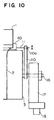
- Figs. 9 and 10 are respectively an illustrative side elevational view and an illustrative front elevational view
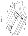
- Figs. 11 and 12 are a perspective view and a side elevational cross-sectional view respectively showing a structure and fitted condition of an elastic seal member thereof
- Fig. 13 is a side-elevational cross-sectional view showing a mounted condition of the elastic seal member
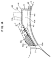
- Fig. 14 is a side-elevational cross-sectional view showing a mounted condition of the elastic seal member different in size from Fig. 13 member
- Figs. 15 and 16 are illustrative side elevational views each for describing an example of operations thereof.
- the same numerals as those in the above description denote the same or corresponding portions, and hence, the explanation thereof will sometimes be omitted.
- the casting apparatus is also composed of a T die (die) 1 for extruding a resin molten by an extruding machine (not shown) into a film-like or sheet-like membrane 2, a casting roll (cooling roll) 3 for receiving the membrane 2 extruded from the T die 1 on its outer circumferential surface to cool and deliver it, and a suction chamber 40 for sucking air between the membrane 2 and the casting roll 3 to make the membrane 2 stably come closely into contact with the surface of the casting roll 3.
- the casting roll 13 is supported on a roll supporting shaft 16 to be rotatable with respect to a side frame 17, wheels 18 to be used when moving this apparatus in a horizontal direction are fitted to lower portions of the side frame 17.
- the suction chamber 40 is provided independently of the T die 1. Further, the suction chamber 40 is formed along the outer circumferential surface of the casting roll 3, and a necessary seal gap is defined between the suction chamber 40 and the outer circumferential surface of the casting roll 3. The dimension (interval) of this gap is set to ensure a necessary suction force (pressure reduction level) in a close contact section between the membrane 2 and the casting roll 3 concurrently with allowing the rotation of the casting roll 3.
- the suction chamber 40 is constructed as being similar to the suction chamber 40 in the fourth embodiment described before with reference to Figs. 4 to 7.
- a vacuum pump 5 is coupled through a suction duct 60 to the suction chamber 40, and on the operation of the vacuum pump 5, the air between the membrane 2 and the casting roll 3 is sucked through a suction inlet (opening section) 40a of the suction chamber 40. Further, the suction inlet 40a is formed throughout the overall width of the membrane 2 in the proximity of a portion at which the membrane 2 starts to come closely into contact with the outer circumferential surface of the casting roll 3.
- a driving member 110 is used as a circumferentially moving mechanism for moving the suction chamber 40 along the circumferential directions of the casting roll 3 while holding the necessary seal gap.
- This driving member 110 is constructed such that its proximal side is supported coaxially with a roll supporting shaft (rotary shaft) 16 of the casting roll 3 to be rotatable around the roll shaft 16 (directions of arrows A in Fig. 9) while its tip side is fixed to the suction chamber 40.
- the driving member 110 has two elongated holes 110a made along the radial directions of the casting roll 3, and by adjusting the tightening positions of supporting bolts 11 penetrating these elongated holes 110a, the suction chamber 40 is fitted with respect to the driving member 110 to be movable in the radial directions of the casting roll 3, that is, so that a necessary seal gap between the outer circumferential surface of the casting roll 3 and the suction chamber 40 is adjustable.
- a radially moving mechanism is constructed with the aforesaid elongated holes 110a and supporting bolts 11. In Fig. 10, only one end portion side of the apparatus according to this embodiment in the width direction is shown, but the other end portion side is constructed in a similar way.
- an elastic seal member 50 is interposed between the T die 1 and the suction chamber 40 and the interval between the T die 1 and the suction chamber 40 is sealed with the elastic seal member 50.
- This elastic seal member 50 is disposed throughout a width exceeding the overall width of the membrane 2 as well as the elastic seal member 50 in the fourth embodiment described with reference to Figs. 4 to 7, and is composed of an elastic seal body 51 and fixtures (fitting tools) 52, 53 as shown in Figs. 11 to 14.
- the elastic seal body 51 is made of a foaming agent such as a polyimide foam having an excellent heat resistance, a high impact resilience and a less compressive permanent strain, and formed into a semicircular bar-like configuration in cross section, with its front surface being covered with a glass cloth (made by integrally adhering an aluminium foil through an adhesive to a glass cloth) coated with an aluminium foil.
- a foaming agent such as a polyimide foam having an excellent heat resistance, a high impact resilience and a less compressive permanent strain
- This elastic seal body 51 is fixed to the suction chamber 40 in a manner that its lower portion is held between rising portions 52b, 53b of the fixtures 52, 53 in the forward and backward directions and the fixtures 52, 53 are fixedly tightened with fitting bolts 55 with respect to the upper wall 41a of the suction chamber 40.
- the elastic seal member 50 closes the gap between the T die 1 and the suction chamber 40 in a manner that the elastic seal body 51 is pressed by an elastic force to be brought into contact with the T die 1.
- the fixture 53 is disposed to be placed on the fixture 52, and in a state where elongated holes 52a made on the fixture 52 side are aligned with elongated holes 53a made on the fixture 53 side, the fitting bolts 55 are inserted through washers 54 into these elongated holes 52a, 53a and tightened with respect to the upper wall 41a of the suction chamber 40 so that the fixtures 52, 53 are fixed integrally.
- upper wall 41a side female screws to be engaged with the fitting bolts 55 are constructed as blind screws in a rear plate 41e.
- the elongated holes 52a are made for the purpose of changing the position of the fixture 53 so that elastic seal bodies 51 different in size can be fitted to the suction chamber 40.
- the apparatus according to the sixth embodiment takes an operation similar to that in the first embodiment shown in Fig. 1.
- the interval between the T die 1 and the casting roll 3 is enlarged by retreating the casting roll 3.
- the side surface opening section made by the membrane 2, the outer circumferential surface of the casting roll 3 and the tip portion of the suction chamber 40 enlarges, so that difficulty is experienced to reach the necessary pressure reduction level.
- the suction chamber 40 fitted to the driving member 110 is advanced to a given position to make the side surface opening section small and the air within the suction chamber 40 is sucked by the vacuum pump 5 up to a necessary pressure reduction level, so that the membrane 2 in a molten condition immediately after the extrusion from the T die 1 can stably be brought closely into contact with the casting roll 3.
- the elastic seal member 50 is interposed between the T die 1 and the suction chamber 40, and therefore, the elastic seal member 50 can close the gap between the T die 1 and the suction chamber 40 while following that variation.
- the elastic seal member 50 elastically deforms to automatically continue to close the gap therebetween.
- the airtightness of the pressure reduction space surrounded by the T die 1, the membrane 2 and the suction chamber 40 is securable, thus surely obtaining the necessary pressure reduction level in that pressure reduction space.
- Figs. 13 and 14 the contour configuration of the elastic seal member 50 before the movement of the suction chamber 40 (the contour configuration before being p ressed by the T die 1 to deform) is shown with a dashed line 50a.
- the elastic seal member 50 itself is replaced with an elastic seal member with a different size for adjustment.
- the elastic seal member 50 is attached to the lower surface of the T die 1 and is pressed with an elastic force to come into contact with the upper surface side of the suction chamber 40.
- the suction chamber 40 is movable in the circumferential directions of the casting roll 3 while keeping a necessary seal gap with respect to the casting roll 3, and further is movable in the radial directions of the casting roll 3, and hence, the seal gap between the suction chamber 40 and the casting roll 3 is adjustable, besides the elastic seal member 50 can seal the gap between the lower surface of the T die 1 and the upper surface of the suction chamber 40 irrespective of the dimension of the gap.
- the interval between the T die 1 and the casting roll 3 can appropriately set for any kind of resin, with the result that the necessary film characteristic (membrane characteristic) is securable to sharply enhancing the quality of the resin-made membrane (film or sheet) 2.
- Figs. 17A to 17C are side-elevational cross-sectional views each showing a structure and fitted condition of an elastic seal member in a resin-made membrane formation casting apparatus according to a seventh embodiment of this invention.
- Each of these plate springs 56a to 56c is made from a thin metal (its plate thickness is at 1 mm or below 1 mm) with a corrosion resistance such as a stainless steel as in the case of the fifth embodiment, and is disposed throughout a width exceeding the overall width of the membrane 2 and is attached through a fitting bolt 55 to the upper wall 41a of the suction chamber 40. Further, each of the metallic plate springs 56a to 56c is pressed with an elastic force to come into contact with the lower surface of the T die 1, there by closing the gap between the lower surface of the T die 1 and the upper surface of the suction chamber 40.
- the plate spring 56a shown in Fig. 17A has a configuration in which its tip portion is inflated into an arc shape to be returned, and the plate spring 56b shown in Fig. 17B has an angle configuration having an arc portion at an upper section, and the plate spring 56c shown in Fig. 17C has a hook-like configuration in which its tip side is directed upwardly.
- the condition deformed by the contact with the T die 1 is indicated with a two-dot chain line.
- plate springs 56a to 56c are made to close the gap by being brought with an elastic force into contact with both the lower surface of the T die 1 and the upper surface of the suction chamber 40, and hence, the configuration is not limited to those shown in Figs. 17A to 17C. Further, it is also appropriate that each of the plate springs 56a to 56c is fitted to the lower surface of the T die 1 whereas being pressed with an elastic force to come into contact with the upper surface side of the suction chamber 40.
- each of the plate springs 56a to 56c themselves is replaced with a plate spring with a different size for adjustment.
- the resin-made membrane formation casting apparatus according to the seventh embodiment of this invention can also offer the same effects as those of the sixth embodiment by using the plate springs 56a to 56c shown in Figs. 17A to 17C.
- Figs. 18 to 20 are illustrations of a casting apparatus for resin-made membrane formation according to an eighth embodiment of this invention.
- Fig. 18 is a side elevational view illustratively showing the apparatus
- Fig. 19 is a perspective view showing structures and fitted conditions of an elastic seal member and a shielding plate in the apparatus
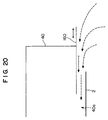
- Fig. 20 is an illustration of an outside air inflow situation in a cross section taken along a line P-P of Fig. 18.
- the same numerals as those in the above explanation designate the same or corresponding parts, and the description thereof will be omitted.
- a shielding plate 160 for suppressing the suction occurring through the end portion by shielding the end portion opening, with the shielding plate 160 being movable in the width directions of a membrane 2.
- the shielding plate 160 has an elongated hole 160a made therein, and is fitted to the suction chamber 40 by means of fitting bolts 162 which are placed to penetrate the elongated hole 160a and are tightened through washers 161 with respect to an upper wall 41a of the suction chamber 40.
- the shielding plate 160 is movable in the width directions of the membrane 2 owing to the elongated hole 160 so that the shielding amount of the end portion of the suction inlet 40a of the suction chamber 40 is adjustable.
- Fig. 19 shows only one end portion side of the apparatus according to this embodiment in the width directions, the other end portion side is constructed in a similar way.
- this embodiment can fulfill great effects when the membrane 2 is stably brought closely into contact with the casting roll 3 in the case of using a resin with a relatively low extension viscosity for the membrane formation.
- the shielding plate 160 is shifted in accordance with the necking quantity of the membrane 2, the air flow is appropriately controllable.
- Figs. 21 to 23 illustrate a casting apparatus for resin-made membrane formation according to a ninth embodiment of this invention.
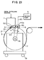
- Fig. 21 is a side elevational view illustratively showing the apparatus
- Fig. 22 is a perspective view showing structures and fitted conditions of an elastic seal member and a suction nozzle in the apparatus
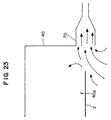
- Fig. 23 is an illustration of an outside air inflow situation in a cross section taken along a line Q-Q of Fig. 21.
- the same numerals as those in the above explanation depict the same or corresponding parts, and the description thereof will be omitted.
- This ninth embodiment is substantially constructed like the above-described sixth embodiment as shown in Fig. 21, except that, as shown in Figs. 21 and 22, to an end portion of a suction inlet (suction opening section) 40a of a suction chamber 40, there is fitted a side suction nozzle 70 which sucks air from a side of the end portion.
- This side suction nozzle 70 is coupled to a vacuum pump 71 and the air at the end portion of the suction inlet 40a of the suction chamber 40 is sucked through the side suction nozzle 70 by the vacuum pump 71.
- the Fig. 22 shows only one end portion of the apparatus according to this embodiment in the width directions, the other end portion side is constructed in a similar way.
- the operation of the resin-made membrane formation casting apparatus according to the ninth embodiment thus arranged is the same as that of the sixth embodiment, and therefore, the description thereof to be made referring to Fig. 23 is limited to only the effects of the side suction nozzle 70.
- the flow due to the suction by the side suction nozzle 70 is a main flow so that the dynamic pressure and the formation of eddy are suppressible and, hence, the vibrations (rocking) of the membrane 2 or the introduction thereof into the suction chamber 40 is suppressible, with the result that the stable membrane formation is feasible irrespective of the kind of resin.
- this embodiment can fulfill great effects when the membrane 2 is stably brought closely into contact with the casting roll 3 in the case of using a resin with a relatively low extension viscosity for the membrane formation.
- the air flow is appropriately controllable.
- Figs. 24 to 26 are illustrations of a casting apparatus for resin-made membrane formation according to a tenth embodiment of this invention.
- Fig. 24 is a side elevational view illustratively showing the apparatus
- Fig. 25 is a perspective view showing structures and fitted conditions of an elastic seal member, a shielding plate and a suction nozzle in the apparatus
- Fig. 26 is an illustration of an outside air inflow situation in a cross section taken along a line R-R of Fig. 24.
- the same numerals as those in the above explanation designate the same or corresponding parts, and the description thereof will be omitted.
- This tenth embodiment has the substantially same structure as that of the above-described sixth embodiment as shown in Fig. 24, except that both a shielding plate 160 described in the eighth embodiment and side suction nozzle 70 described in the ninth embodiment are provided as shown in Figs. 24 and 25.
- the shielding plate 160 which shields that end portion opening to suppress the suction occurring through the end portion, with the shielding plate 160 being movable in the width directions of a membrane 2.
- this shielding plate 160 that is, the end portion of the suction inlet 40a of the suction chamber 40
- the side suction nozzle 70 which sucks air from a side of the end portion.
- This side suction nozzle 70 is coupled to a vacuum pump 71, so that the air at the end portion of the suction inlet 40a of the suction chamber 40 is sucked through the side suction nozzle 70 by means of the vacuum pump 71.
- an elongated hole 160a is made in the shielding plate 160, and the shielding plate 160 is fitted to the suction chamber 40 in a manner that fitting bolts 162 penetrate the elongated hole 160a and is tightened through washers 161 with respect to an upper wall 41a of the suction chamber 40.
- the shielding plate 160 is movable in the width directions of the membrane 2 owing to the elongated hole 160, thereby adjusting the shielding amount at the end portion of the suction inlet 40a of the suction chamber 40.
- Fig. 25 shows only one end portion side of the apparatus according to this embodiment in the width directions, the other end portion side is constructed in a similar way.
- the operation of the resin-made membrane formation casting apparatus according to the tenth embodiment thus constructed is the same as that of the sixth embodiment, and hence, the description will be made of only the effects of the shielding plate 160 and the side suction nozzle 70 with reference to Fig. 26.
- the flow due to the suction by the side suction nozzle 70 is a main flow, and further the shielding plate 160 commutates the suction into the suction chamber 40, so that the dynamic pressure and the formation of eddy are suppressible and, hence, the vibrations (rocking) of the membrane 2 or the introduction thereof into the suction chamber 40 is suppressible, with the result that the stable membrane formation is feasible irrespective of the kind of resin.
- this embodiment can fulfill great effects when the membrane 2 is stably brought closely into contact with the casting roll 3 in the case of using a resin with a relatively low extension viscosity for the membrane formation.
- the air flow is appropriately controllable.
- Figs. 27 and 28 are respectively a side elevational view and a front elevational view each illustratively showing a casting apparatus for resin-made membrane formation according to an eleventh embodiment of this invention.
- This eleventh embodiment relates to a resin-made membrane formation casting apparatus constructed in a manner that a radially moving mechanism for shifting a suction chamber 40 in radial directions of a casting roll 3 to adjust the seal gap therebetween to a necessary dimension is added to the above-described casting apparatus according to the second embodiment.
- a radially moving mechanism for shifting a suction chamber 40 in radial directions of a casting roll 3 to adjust the seal gap therebetween to a necessary dimension is added to the above-described casting apparatus according to the second embodiment.
- the same numerals as those in the above description designate the same or corresponding parts, and the description thereof will be omitted for brevity.
- a guide frame (guide member) 13 is used as a circumferentially moving mechanism for shifting the suction chamber 40 in the circumferential directions of the casting roll 3 while keeping the necessary seal gap.
- This guide frame 13 is fitted through fitting bolts 12 to a side frame 17 for rotatably supporting a side end portion of a roll supporting shaft 16 of the casting roll 3.
- This guide frame 13 has an elongated hole-like guide rail 13a made to engage with two pins (or rollers) 11a fitted onto a side surface of the suction chamber 40 to guide the suction chamber 40 along the circumferential directions of the casting roll 3.
- the necessary seal gap between the outer circumferential surface of the casting roll 3 and the suction chamber 40 is adjustable. That is, the aforesaid fitting bolts 12 function as the radially moving mechanism.
- Fig. 28 shows only one end portion side of the apparatus according to this embodiment in the width directions, the other end portion side is arranged in a similar way.
- the interval between the lower surface of the T die 1 and the upper surface of the suction chamber 40 is closed with the above-mentioned elastic seal member 50 attached to the suction chamber 40.
- the resin-made membrane formation casting apparatus according to the eleventh embodiment of this invention thus constructed differs from the sixth embodiment only in the constructions of the circumferentially moving mechanism and the radially moving mechanism, and can provide the same effects as those of the sixth embodiment.
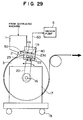
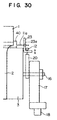
- Figs. 29 and 30 are respectively a side elevational view and a front elevational view illustratively showing a casting apparatus for resin-made membrane formation according to a twelfth embodiment of this invention.
- a radially moving mechanism for shifting a suction chamber 40 in radial directions of a casting roll 3 to adjust the seal gap therebetween to a necessary dimension is provided in the above-described casting apparatus according to the third embodiment.
- the same numerals as those in the above explanation designate the same or corresponding components, and the description thereof will be omitted for simplicity.
- a driving member 20 and a guide frame (guide member) 23 are used as a circumferentially moving mechanism for shifting the suction chamber 40 along the circumferential directions of the casting roll 3 while maintaining the necessary seal gap.
- the driving member 20 in the driving member 20, its proximal side is supported coaxially with a roll supporting shaft 16 of the casting roll 3 to be rotatable around the roll supporting shaft 16 while its tip side is attached through fitting bolts 22 to the guide frame 23.
- This guide frame 23 has an elongated hole-like guide rail 23a made to engage with two pins (or rollers) 11a, 11a fitted to a side surface of the suction chamber 40 to guide the suction chamber 40 along the circumferential directions of the casting roll 3.
- the necessary seal gap between the outer circumferential surface of the casting roll 3 and the suction chamber 40 is adjustable. That is, the aforesaid fitting bolts 22 function as the radially moving mechanism.
- Fig. 30 shows only one end portion side of the apparatus according to this embodiment in the width directions, the other end portion side is arranged in a similar way.
- the interval between the lower surface of the T die 1 and the upper surface of the suction chamber 40 is closed with the above-mentioned elastic seal member 50 attached to the suction chamber 40.
- the rough adjustment is made such that the suction chamber 40 is shifted by the driving member 20 clockwise around the roll supporting shaft 16 to retreat to an adequate position and, subsequently, the fine adjustment is made such that the suction chamber 40 is shifted along the elongated hole-like guide rail 23a of the guide frame 23 to be positioned at a given position.
- This resin-made membrane formation casting apparatus can offer the same effects as those of the third embodiment, and further, because of being different from the sixth embodiment only in the constructions of the circumferentially moving mechanism and the radially moving mechanism, can provide the same effects as those of the sixth embodiment.
Landscapes
- Engineering & Computer Science (AREA)
- Mechanical Engineering (AREA)
- Physics & Mathematics (AREA)
- Thermal Sciences (AREA)
- Extrusion Moulding Of Plastics Or The Like (AREA)
- Separation Using Semi-Permeable Membranes (AREA)
- Casting Or Compression Moulding Of Plastics Or The Like (AREA)
- Ink Jet (AREA)
- Moulding By Coating Moulds (AREA)
- Moulds For Moulding Plastics Or The Like (AREA)
Priority Applications (1)
| Application Number | Priority Date | Filing Date | Title |
|---|---|---|---|
| EP01122544A EP1172196B1 (de) | 1997-04-21 | 1998-04-15 | Giessanlage zur Bildung einer Harzmembrane |
Applications Claiming Priority (3)
| Application Number | Priority Date | Filing Date | Title |
|---|---|---|---|
| JP10358497A JP3349388B2 (ja) | 1996-10-28 | 1997-04-21 | 樹脂製薄膜成形用キャスティング装置 |
| JP103584/97 | 1997-04-21 | ||
| JP10358497 | 1997-04-21 |
Related Child Applications (1)
| Application Number | Title | Priority Date | Filing Date |
|---|---|---|---|
| EP01122544A Division EP1172196B1 (de) | 1997-04-21 | 1998-04-15 | Giessanlage zur Bildung einer Harzmembrane |
Publications (3)
| Publication Number | Publication Date |
|---|---|
| EP0879691A2 true EP0879691A2 (de) | 1998-11-25 |
| EP0879691A3 EP0879691A3 (de) | 1999-08-04 |
| EP0879691B1 EP0879691B1 (de) | 2002-08-14 |
Family
ID=14357833
Family Applications (2)
| Application Number | Title | Priority Date | Filing Date |
|---|---|---|---|
| EP98106789A Expired - Lifetime EP0879691B1 (de) | 1997-04-21 | 1998-04-15 | Giessanlage zur Bildung einer Harzmembrane |
| EP01122544A Expired - Lifetime EP1172196B1 (de) | 1997-04-21 | 1998-04-15 | Giessanlage zur Bildung einer Harzmembrane |
Family Applications After (1)
| Application Number | Title | Priority Date | Filing Date |
|---|---|---|---|
| EP01122544A Expired - Lifetime EP1172196B1 (de) | 1997-04-21 | 1998-04-15 | Giessanlage zur Bildung einer Harzmembrane |
Country Status (9)
| Country | Link |
|---|---|
| US (1) | US6273704B1 (de) |
| EP (2) | EP0879691B1 (de) |
| KR (1) | KR100257642B1 (de) |
| CN (1) | CN1058442C (de) |
| AT (2) | ATE222169T1 (de) |
| DE (2) | DE69826334T2 (de) |
| ID (1) | ID20180A (de) |
| TR (1) | TR199800731A3 (de) |
| TW (1) | TW426601B (de) |
Cited By (2)
| Publication number | Priority date | Publication date | Assignee | Title |
|---|---|---|---|---|
| EP3130446A4 (de) * | 2015-02-04 | 2017-06-07 | Toray Battery Separator Film Co., Ltd. | Vorrichtung und verfahren zur herstellung einer mikroporösen polyolefinharzfolie |
| EP3733373A1 (de) * | 2019-05-02 | 2020-11-04 | Amut S.p.A. | Fabrik und verfahren zur herstellung von kunststoffstretchfolien |
Families Citing this family (5)
| Publication number | Priority date | Publication date | Assignee | Title |
|---|---|---|---|---|
| JP2002096370A (ja) * | 2000-09-26 | 2002-04-02 | Toray Ind Inc | 口金、シートならびにその製造装置および製造方法 |
| US20030062657A1 (en) * | 2001-07-31 | 2003-04-03 | Massachusetts Institute Of Technology | On-chip membrane maker |
| JP5424126B2 (ja) * | 2010-04-26 | 2014-02-26 | 新東工業株式会社 | 減圧造型用フィルム成形装置及び減圧造型用フィルム成形方法 |
| HUE039633T2 (hu) * | 2015-02-04 | 2019-01-28 | Toray Industries | Mikropórusos poliolefin-gyanta lap gyártóberendezése és gyártási eljárása |
| JP6047265B1 (ja) * | 2015-02-04 | 2016-12-21 | 東レバッテリーセパレータフィルム株式会社 | シート製造装置およびシート製造方法 |
Family Cites Families (12)
| Publication number | Priority date | Publication date | Assignee | Title |
|---|---|---|---|---|
| US2688155A (en) * | 1953-03-16 | 1954-09-07 | Eastman Kodak Co | Apparatus and method for controlling the application of plastic material to casting surfaces of sheeting machines |
| US3154608A (en) * | 1961-06-20 | 1964-10-27 | Crown Zellerbach Corp | Method and apparatus for providing optimum optical properties of polyolefins by controlling the extrusion of the material |
| BE625785A (de) * | 1962-12-10 | 1900-01-01 | ||
| US3347962A (en) * | 1965-08-02 | 1967-10-17 | Eastman Kodak Co | Method and apparatus for casting a liquid composition |
| US3579735A (en) * | 1967-07-31 | 1971-05-25 | Crown Zellerbach Corp | Apparatus for balancing pressure applied to film-forming material in the deposition thereof onto a casting surface |
| US4310295A (en) * | 1981-01-28 | 1982-01-12 | E. I. Du Pont De Nemours And Company | Device for uniform web pinning |
| DE3309343C2 (de) * | 1983-03-16 | 1986-08-14 | Du Pont de Nemours (Deutschland) GmbH, 4000 Düsseldorf | Vorrichtung zum Auftragen mindestens einer Gießschicht |
| JPS6357222A (ja) | 1986-08-29 | 1988-03-11 | Toyoda Gosei Co Ltd | 中空体の製造方法 |
| US5154951A (en) * | 1990-03-26 | 1992-10-13 | Eastman Kodak Company | Method and apparatus for use in bead coating a web with liquid composition |
| US5395578A (en) * | 1990-09-17 | 1995-03-07 | Industrie Ilpea S.P.A. | Method for slush molding articles, of two or more colors from thermoplastic, thermosetting or elastomeric resins in powder form |
| FR2698580B1 (fr) * | 1992-12-01 | 1995-02-24 | Albert Plastiques | Dispositif pour plaquer sur un cylindre de refroidissement le film sortant d'une filière plate. |
| US5618568A (en) * | 1995-02-01 | 1997-04-08 | Extrusion Dies, Inc. | Dual-chamber vacuum box |
-
1998
- 1998-04-03 ID IDP980508A patent/ID20180A/id unknown
- 1998-04-15 EP EP98106789A patent/EP0879691B1/de not_active Expired - Lifetime
- 1998-04-15 AT AT98106789T patent/ATE222169T1/de not_active IP Right Cessation
- 1998-04-15 AT AT01122544T patent/ATE276084T1/de not_active IP Right Cessation
- 1998-04-15 DE DE69826334T patent/DE69826334T2/de not_active Expired - Fee Related
- 1998-04-15 EP EP01122544A patent/EP1172196B1/de not_active Expired - Lifetime
- 1998-04-15 DE DE69807143T patent/DE69807143T2/de not_active Expired - Fee Related
- 1998-04-17 KR KR1019980013730A patent/KR100257642B1/ko not_active Expired - Fee Related
- 1998-04-17 US US09/061,259 patent/US6273704B1/en not_active Expired - Fee Related
- 1998-04-18 TW TW087105956A patent/TW426601B/zh not_active IP Right Cessation
- 1998-04-20 CN CN98106687A patent/CN1058442C/zh not_active Expired - Fee Related
- 1998-04-21 TR TR1998/00731A patent/TR199800731A3/tr unknown
Cited By (2)
| Publication number | Priority date | Publication date | Assignee | Title |
|---|---|---|---|---|
| EP3130446A4 (de) * | 2015-02-04 | 2017-06-07 | Toray Battery Separator Film Co., Ltd. | Vorrichtung und verfahren zur herstellung einer mikroporösen polyolefinharzfolie |
| EP3733373A1 (de) * | 2019-05-02 | 2020-11-04 | Amut S.p.A. | Fabrik und verfahren zur herstellung von kunststoffstretchfolien |
Also Published As
| Publication number | Publication date |
|---|---|
| TW426601B (en) | 2001-03-21 |
| TR199800731A2 (xx) | 2000-02-21 |
| US6273704B1 (en) | 2001-08-14 |
| DE69826334T2 (de) | 2005-10-20 |
| ATE276084T1 (de) | 2004-10-15 |
| KR100257642B1 (ko) | 2000-06-01 |
| DE69807143D1 (de) | 2002-09-19 |
| EP1172196B1 (de) | 2004-09-15 |
| DE69807143T2 (de) | 2002-12-12 |
| EP1172196A1 (de) | 2002-01-16 |
| CN1197723A (zh) | 1998-11-04 |
| CN1058442C (zh) | 2000-11-15 |
| ID20180A (id) | 1998-10-22 |
| KR19980081494A (ko) | 1998-11-25 |
| EP0879691A3 (de) | 1999-08-04 |
| DE69826334D1 (de) | 2004-10-21 |
| EP0879691B1 (de) | 2002-08-14 |
| ATE222169T1 (de) | 2002-08-15 |
| TR199800731A3 (tr) | 2000-02-21 |
Similar Documents
| Publication | Publication Date | Title |
|---|---|---|
| EP0879691B1 (de) | Giessanlage zur Bildung einer Harzmembrane | |
| US7373880B2 (en) | Variable format offset printing press | |
| JP4234816B2 (ja) | 金属ストリップ連続鋳造装置 | |
| JP3349388B2 (ja) | 樹脂製薄膜成形用キャスティング装置 | |
| EP0285368B1 (de) | Blasenformende und stabilisierende Vorrichtung zum Gebrauch im kontinuierlichen Extrusionsverfahren zur Herstellung von Blasfolien | |
| EP0293929A1 (de) | Vorrichtung zum kontinuierlichen Behandeln unter Vakuum | |
| US4032284A (en) | Die assembly | |
| JP3605374B2 (ja) | 樹脂製薄膜成形用キャスティング装置 | |
| JP4068449B2 (ja) | 塗膜形成装置及び塗膜形成方法 | |
| CN220444873U (zh) | 金属管材挤压机用成品管材校正装置 | |
| CN218132976U (zh) | 一种逗号涂布设备 | |
| JP4677150B2 (ja) | フィルムキャスティング装置 | |
| CN112157903B (zh) | 一种型材贴膜机的压膜机构及其压膜方法 | |
| JP2002528269A (ja) | 浮動塗布ダイ搭載装置 | |
| JP3442985B2 (ja) | 樹脂製薄膜成形用キャスティング装置 | |
| CN223878328U (zh) | 一种工艺画成品套膜装置 | |
| JP4689847B2 (ja) | コロナ放電電極、コロナ放電方法及びシートキャスティング機 | |
| CN119296885B (zh) | 一种用于漆包线加工的导线涂漆设备 | |
| CN115476493B (zh) | 一种既能生产流延膜又能生产pp膜的生产设备及其工艺 | |
| JPS6026976Y2 (ja) | フイルム等帯状物の成形機 | |
| CN224044513U (zh) | 一种复合流延膜挤出装置 | |
| JPH08216227A (ja) | ベルト挟圧式発泡シート成形装置 | |
| CN121023613A (zh) | 一种用于凹印版辊表面镀铜的均匀性控制装置 | |
| JPH0414426A (ja) | フィルム・シートの成形装置 | |
| JPH1177796A (ja) | フィルム押出成形装置 |
Legal Events
| Date | Code | Title | Description |
|---|---|---|---|
| PUAI | Public reference made under article 153(3) epc to a published international application that has entered the european phase |
Free format text: ORIGINAL CODE: 0009012 |
|
| AK | Designated contracting states |
Kind code of ref document: A2 Designated state(s): AT DE FI IT |
|
| AX | Request for extension of the european patent |
Free format text: AL;LT;LV;MK;RO;SI |
|
| PUAL | Search report despatched |
Free format text: ORIGINAL CODE: 0009013 |
|
| AK | Designated contracting states |
Kind code of ref document: A3 Designated state(s): AT BE CH CY DE DK ES FI FR GB GR IE IT LI LU MC NL PT SE |
|
| AX | Request for extension of the european patent |
Free format text: AL;LT;LV;MK;RO;SI |
|
| 17P | Request for examination filed |
Effective date: 19990914 |
|
| AKX | Designation fees paid |
Free format text: AT DE FI IT |
|
| GRAG | Despatch of communication of intention to grant |
Free format text: ORIGINAL CODE: EPIDOS AGRA |
|
| 17Q | First examination report despatched |
Effective date: 20000911 |
|
| GRAG | Despatch of communication of intention to grant |
Free format text: ORIGINAL CODE: EPIDOS AGRA |
|
| GRAG | Despatch of communication of intention to grant |
Free format text: ORIGINAL CODE: EPIDOS AGRA |
|
| GRAH | Despatch of communication of intention to grant a patent |
Free format text: ORIGINAL CODE: EPIDOS IGRA |
|
| GRAH | Despatch of communication of intention to grant a patent |
Free format text: ORIGINAL CODE: EPIDOS IGRA |
|
| GRAA | (expected) grant |
Free format text: ORIGINAL CODE: 0009210 |
|
| AK | Designated contracting states |
Kind code of ref document: B1 Designated state(s): AT DE FI IT |
|
| REF | Corresponds to: |
Ref document number: 222169 Country of ref document: AT Date of ref document: 20020815 Kind code of ref document: T |
|
| REF | Corresponds to: |
Ref document number: 69807143 Country of ref document: DE Date of ref document: 20020919 |
|
| PLBE | No opposition filed within time limit |
Free format text: ORIGINAL CODE: 0009261 |
|
| STAA | Information on the status of an ep patent application or granted ep patent |
Free format text: STATUS: NO OPPOSITION FILED WITHIN TIME LIMIT |
|
| 26N | No opposition filed |
Effective date: 20030515 |
|
| PGFP | Annual fee paid to national office [announced via postgrant information from national office to epo] |
Ref country code: FI Payment date: 20050414 Year of fee payment: 8 |
|
| PG25 | Lapsed in a contracting state [announced via postgrant information from national office to epo] |
Ref country code: FI Free format text: LAPSE BECAUSE OF NON-PAYMENT OF DUE FEES Effective date: 20060415 |
|
| PGFP | Annual fee paid to national office [announced via postgrant information from national office to epo] |
Ref country code: IT Payment date: 20060430 Year of fee payment: 9 |
|
| PGFP | Annual fee paid to national office [announced via postgrant information from national office to epo] |
Ref country code: DE Payment date: 20070412 Year of fee payment: 10 Ref country code: AT Payment date: 20070412 Year of fee payment: 10 |
|
| PG25 | Lapsed in a contracting state [announced via postgrant information from national office to epo] |
Ref country code: DE Free format text: LAPSE BECAUSE OF NON-PAYMENT OF DUE FEES Effective date: 20081101 |
|
| PG25 | Lapsed in a contracting state [announced via postgrant information from national office to epo] |
Ref country code: AT Free format text: LAPSE BECAUSE OF NON-PAYMENT OF DUE FEES Effective date: 20080415 |
|
| PG25 | Lapsed in a contracting state [announced via postgrant information from national office to epo] |
Ref country code: IT Free format text: LAPSE BECAUSE OF NON-PAYMENT OF DUE FEES Effective date: 20070415 |