EP0880995A2 - Verfahren zur Herstellung und System zur Granulierung von pulverförmigen Material - Google Patents
Verfahren zur Herstellung und System zur Granulierung von pulverförmigen Material Download PDFInfo
- Publication number
- EP0880995A2 EP0880995A2 EP98109792A EP98109792A EP0880995A2 EP 0880995 A2 EP0880995 A2 EP 0880995A2 EP 98109792 A EP98109792 A EP 98109792A EP 98109792 A EP98109792 A EP 98109792A EP 0880995 A2 EP0880995 A2 EP 0880995A2
- Authority
- EP
- European Patent Office
- Prior art keywords
- air
- pulsating vibration
- powdered material
- granulation tank
- granulation
- Prior art date
- Legal status (The legal status is an assumption and is not a legal conclusion. Google has not performed a legal analysis and makes no representation as to the accuracy of the status listed.)
- Ceased
Links
Images


Classifications
-
- B—PERFORMING OPERATIONS; TRANSPORTING
- B01—PHYSICAL OR CHEMICAL PROCESSES OR APPARATUS IN GENERAL
- B01J—CHEMICAL OR PHYSICAL PROCESSES, e.g. CATALYSIS OR COLLOID CHEMISTRY; THEIR RELEVANT APPARATUS
- B01J2/00—Processes or devices for granulating materials, e.g. fertilisers in general; Rendering particulate materials free flowing in general, e.g. making them hydrophobic
- B01J2/16—Processes or devices for granulating materials, e.g. fertilisers in general; Rendering particulate materials free flowing in general, e.g. making them hydrophobic by suspending the powder material in a gas, e.g. in fluidised beds or as a falling curtain
-
- B—PERFORMING OPERATIONS; TRANSPORTING
- B01—PHYSICAL OR CHEMICAL PROCESSES OR APPARATUS IN GENERAL
- B01J—CHEMICAL OR PHYSICAL PROCESSES, e.g. CATALYSIS OR COLLOID CHEMISTRY; THEIR RELEVANT APPARATUS
- B01J2/00—Processes or devices for granulating materials, e.g. fertilisers in general; Rendering particulate materials free flowing in general, e.g. making them hydrophobic
- B01J2/18—Processes or devices for granulating materials, e.g. fertilisers in general; Rendering particulate materials free flowing in general, e.g. making them hydrophobic using a vibrating apparatus
-
- F—MECHANICAL ENGINEERING; LIGHTING; HEATING; WEAPONS; BLASTING
- F26—DRYING
- F26B—DRYING SOLID MATERIALS OR OBJECTS BY REMOVING LIQUID THEREFROM
- F26B3/00—Drying solid materials or objects by processes involving the application of heat
- F26B3/02—Drying solid materials or objects by processes involving the application of heat by convection, i.e. heat being conveyed from a heat source to the materials or objects to be dried by a gas or vapour, e.g. air
- F26B3/06—Drying solid materials or objects by processes involving the application of heat by convection, i.e. heat being conveyed from a heat source to the materials or objects to be dried by a gas or vapour, e.g. air the gas or vapour flowing through the materials or objects to be dried
- F26B3/08—Drying solid materials or objects by processes involving the application of heat by convection, i.e. heat being conveyed from a heat source to the materials or objects to be dried by a gas or vapour, e.g. air the gas or vapour flowing through the materials or objects to be dried so as to loosen them, e.g. to form a fluidised bed
- F26B3/092—Drying solid materials or objects by processes involving the application of heat by convection, i.e. heat being conveyed from a heat source to the materials or objects to be dried by a gas or vapour, e.g. air the gas or vapour flowing through the materials or objects to be dried so as to loosen them, e.g. to form a fluidised bed agitating the fluidised bed, e.g. by vibrating or pulsating
- F26B3/0926—Drying solid materials or objects by processes involving the application of heat by convection, i.e. heat being conveyed from a heat source to the materials or objects to be dried by a gas or vapour, e.g. air the gas or vapour flowing through the materials or objects to be dried so as to loosen them, e.g. to form a fluidised bed agitating the fluidised bed, e.g. by vibrating or pulsating by pneumatic means, e.g. spouted beds
Definitions
- the present invention relates to a production method and system for granulating powdered material, and more particularly relates to a production method and system for efficiently granulating powdered material with uniform property and small specific volume using pulsating vibration air.
- Fig.12 shows a fluidized layer granulation system of according to a prior art.
- the granulation system 101 is comprised of a granulation tank 102, an air source 103 such as a blower fan, a discharge fan 104, a heating means 105 such as a heat exchanger, and a spray means 106 for spraying a binding solution such as a nozzle means for spraying a binding solution.
- an air source 103 such as a blower fan, a discharge fan 104, a heating means 105 such as a heat exchanger, and a spray means 106 for spraying a binding solution such as a nozzle means for spraying a binding solution.
- a supply port 102a for introducing heated air is provided under the granulation tank 102, the air source 103 is connected to the supply port 102a via a conduit pipe and the heating means 105 is provided between the supply port 102a and the air source 103.
- the air source 103 is driven to cause the heating means 105 also to drive, the air produced by the air source 103 is heated by the heating means 105, the heated air is supplied into the granulation tank 102 from the supply port 102a, and the supplied air is blown up in the granulation tank.
- a fluidization bed 107 is provided above the supply port 102a in the granulation tank 102.
- the powdered material A stored in the granulation tank 102 is deposited on the fluidization bed 107 when air isn't supplied to the granulation tank 102.
- the powdered material A deposited on the fluidization bed 107 floats to be mixed with the air blown upward from the fluidization bed 107 and forms a fluidized layer following the increase of the wind speed of the supplied air.
- a discharge port 102b is provided on the top of the granulation tank 102 and the discharge fan 104 is connected to the port 102b via a conduit pipe.
- the air supplied to the granulation tank 102 is discharged to the outside by driving the fan 104.
- the spray means 106 for spraying a binding solution is provided in the granulation tank 102 and connected with an air source 108 storing pressurized air via an air supply pipe 109, and further a tank 110 for storing a binding solution is connected via a binding solution supply pipe 111.
- a control unit 112 for adjusting the spraying amount of the spray means 106 is interposed in the middle of the pipe 111.
- the numeral 113 relates to a bag filter for preventing the raw powdered material A, the granulating material or the granulated material from flowing out of the granulation tank 102 and the numeral 114 relates to a dust collecting filter for eliminating dust in the air supplied to the granulation tank 102.
- the raw material A is stored in the granulation tank 102. Heated air is supplied into the tank 102 by driving the air source 103 and the heating means 105 and simultaneously the discharge fan 104 is driven, whereby the raw material A placed on the fluidization bed 107 is caused to be blown up.
- the heated air with constant flow amount and constant pressure is always supplied into the tank 102 by controlling the driving force of the air source 103 and the discharge fan 104 so that a desired stable fluidized layer is formed in the tank 102.
- air with a fixed pressure is supplied to the spray means 106 for spraying a binding solution from the air source 108 and simultaneously the control unit 112 is driven.
- a binding solution B is sprayed from a desired spray and makes a bridge of solution between particles of the raw material A.
- the particles of the raw material A suspending in the granulation tank 102 as a fluidized layer mixed with air are aggregated and the aggregated particles are dried to be grown as a granulated material.
- the granulated material with uniform physical property can be produced when material is granulated by spraying a binding solution from the nozzle after a dilute fluidized layer is formed by supplying a large amount of heated air with constant pressure and constant amount into the granulation tank 102.
- Fig.13 is a partially cutaway sectional view of the system disclosed in JP-A-60-183030.
- a granulation system 201 is further provided with a rotary vane 202a on the fluidization bed 107 and a driving motor 202 to rotate the rotary vane 202a below the bed 107. Heated air is supplied into the granulation tank 102 and the motor 202 is driven to rotate the vane 202a when the material A stored in the tank 102 is granulated. The material A directly receives rotating power of the vane 202a so that the material is prevented from being porous because of agitation.
- granulated material with a constant property is produced when material is granulated in a dilute fluidized layer by supplying a large amount of heated air into the granulation tank 102.
- concentration of the material A in a fluidized layer is dense and each particle of the material A doesn't have enoughly opportunity to touch each other so that the growth of particles becomes slow and the productivity of granulation becomes worth.
- each particle of the material A comes to collide frequently so that the growth of particles becomes fast.
- the particle diameter of the granulated material doesn't become uniform or projected parts like an antenna of a snail are formed on the surface of the particles so that granulated material with irregular shape (not spherical) and different diameter is produced. Therefore, the system 101 can't be used when spherical granulated material is required.
- the granulated material tends to be porous because the granulation is executed in an air. As the result, it is difficult to produce granulated material with small specific volume.
- Slacking, bubbling or chanelling of the material A which stop fluidization, may be caused in the granulation tank 102 while the material is granulated.
- the particle diameter, particle shape, density, and hardness of the granulated material depend on a fluidized condition of the raw material A and the granulating material.
- unintended fine particles may be included in the granulated material. It is desired to less the amount of such fine particles.
- the granulated material is prevented from being porous because of the rotary agitation flow by means of the rotation of the vane 202a.
- Foreign material may be produced from the increased parts and the complication makes the cleaning of the system difficult. Such a foreign material remained in the system may be included in the granulated material and increases the risk of contamination. Therefore, such a system isn't appropriate for producing granulated material for fine chemical use such as medicine wherein a high quality granulation without contamination of foreign material is required.
- An object of the present invention is to provide a granulation method and system wherein granulated material with uniform shape, uniform diameter and uniform property and small specific volume can be easily and efficiently produced.
- powdered material stored in a granulation tank is produced into a granulated material with high density and small specific volume as follows.
- the powdered material is fluidized by applying heated pulsating vibration air and is aggregated by spraying a binding solution. Therefore, the aggregated powdered material drops and deposits on a fluidization bed by its gravity accompanied by the growth of the particles while suspending up and down in the granulation tank according to the frequency of the pulsating vibration air. And thereafter the deposited powdered material under granulation is produced into the granulated material with high density and small specific volume while receiving compression to be high density by means of the heated pulsating vibration air.
- the deposited material under granulation is compressed to be high density by means of the vibration of the pulsating vibration air. Therefore, the projections like an antenna of a snail formed on the surface of the particles of the granulating material are peeled off and each particle of the granulating material deposited on the fluidized bed is compressed together.
- the produce of the granulated material with the projections or porous property is prevented and granulated material with uniform property, high density and small specific volume is produced efficiently without difficulty comparing to the prior art wherein powdered material is fluidized by means of constant heated air to be mixed in the heated air, a binding solution is sprayed to aggregate the material, and then the material is dried to grow as granulated material.
- pulsating vibration air with peaks and valleys of negative pressure, air with peaks of atmospheric pressure and valleys of negative pressure, air with peaks of positive pressure and valleys of atmospheric pressure, and air with peaks and valleys of positive pressure. According to experimental findings, the granulated material with small specific volume and good quality can be obtained when pulsating vibration air with peaks and valleys of positive pressure is used.
- Positive pressure means a condition that the pressure in the granulation tank is higher than the outside pressure (atmospheric pressure).
- Negative pressers means a condition that the pressure in the granulation tank is lower than the outside pressure (atmospheric pressure).
- the amplitude, frequency and wave shape of pulsating vibration air are desirable to be changed according to the property of the powdered material (such as viscosity, diameter, specific gravity, adhesiveness, and miscibility with air of the particles of the material) in order to produce granulated material with uniform property and small specific volume.
- At least either of the amplitude, frequency and wave shape of pulsating vibration air is changed according to the property of the material.
- granulated material with small specific volume that is heavy material, can be obtained when the frequency of pulsating vibration air is not less than 1Hz and less than 10Hz, desirably from 1Hz to 9Hz, more desirably from 1Hz to 6Hz, still more desirably 5Hz as the result of production with pulsating vibration air with different frequency.
- Granulation system with an air suction means provided for an air discharge port attached at the top of a granulation tank, with an air supply means provided for an air supply port at the bottom of a granulation tank, with both the air suction means and the air supply means may be considered.
- pulsating vibration means when the pulsating vibration means is provided before the air supply port at the bottom of the granulation tank and pulsating vibration air is supplied under a fluidization bed to upward, it is easy to fluidize the raw material and suspend a part of the material up and down. Further, compression by means of the vibration of the pulsating vibration air is efficiently applied on the granulation and growing material which has been dropped and deposited on the fluidization layer and the material becomes dense, whereby the granulated material with specific volume is produced.
- the granulation system of the present invention is provided with a granulation tank for storing powdered material to be granulated.
- the granulation tank has a supply port for introducing heated air at the bottom thereof, a discharge port for discharging the introduced heated air at the top thereof, and a fluidization bed provided above the supply port for placing the powdered material temporarily.
- the granulation tank is also provided with a spray means for spraying a binding solution to grow the powdered material to be granulated.
- the system is also provided with an air source connected to the supply port of the granulation tank via a conduit pipe, a heating means interposed in the conduit pipe for heating the air generated from the air source, and a pulsating vibration air generation means interposed in the conduit pipe for converting the air generated from the air source to pulsating vibration air.
- a pulsating vibration air generation means may be provided with an on-off valve for closing and opening the conduit pipe connecting the air source and the granulation tank so that pulsating vibration air is generated by operating the valve, may generate pulsating vibration air by vibrating a plate by means of the air supplied from an air source, or may be provided with an air suction means at an air discharge port at the top of a granulation tank and an on-off valve for opening and closing a conduit pipe connecting the air discharge port and the air suction means and pulsating vibration air is generated by operating the valve.
- a rotary type pulsating vibration air generation means is desirable in order to produce granulated material with small specific volume, and more preferably, the rotary type pulsating vibration air generation means is preferably provided between the conduit pipe connecting the air source and the granulation tank.
- the pulsating vibration air generation means as mentioned above may be provided with a casing having a pair of connecting ports at the surrounding wall thereof and a rotary valve having a rotational axis in the center of the casing.
- the valve is constructed so as to divide the inside of the casing into at least two spaces.
- One of the pair of connecting ports is connected with the heated air supply port and the other port is connected with the air source.
- Some materials to be granulated are easy to be mixed with air and the others are not. Therefore, it may be preferable to change the wave shape of the pulsating vibration air in order to fluidize the material stored in the granulation tank and make some of the aggregated material suspend up and down according to the frequency of the pulsating vibration air.
- the above-mentioned pulsating vibration air generation means is provided with a valve for opening and closing the conduit pipe connecting the air source and the heated air supply port, and a valve cam mechanism having guide rails with a specific circular pattern defining the duration and amount of open and close of the valve.
- the valve is opened or closed vertically in compliance with the irregular pattern of the guide rails by driving the valve cam mechanism
- Fig. 1 shows a granulation system of the present invention diagrammatically.
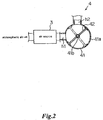
- Fig. 2 is a diagrammatic sectional view of a pulsating vibration air generation means.
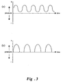
- Figs. 3(a) and 3(b) show examples of pulsating vibration air applied in the present invention.
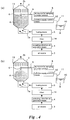
- Fig. 4 shows a phenomenon of the inside of the granulation tank according to the present invention.
- pulsating vibration air is at its peak and in Fig. 4(b) pulsating vibration air is at its valley.
- Fig. 5 is a graph showing the result of the experiment wherein the amount of air required for granulating the material of the same specific volume is compared in the present invention and the prior art.
- Fig. 6 is a graph showing the correlation of the amount of air used for granulation and the breaking load of the granulated material.
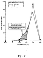
- Fig. 7 shows a graph compared particle size distribution of the granulated material produced by the prior art and the granulated material produced by the present invention.
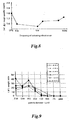
- Fig. 8 is a graph showing the correlation of the frequency of the pulsating vibration air used for granulation and the rough specific volume of the granulated material.
- Fig. 9 is a graph showing the correlation of the frequency of the pulsating vibration air used for granulation and the particle size distribution of the granulated material.
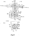
- Fig. 10 shows a pulsating vibration air generation means.
- Fig. 10(a) shows a sectional side view and
- Fig. 10(b) shows a sectional view along with X-X line in Fig. 10(a).
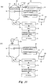
- Fig. 11 shows a diagrammatic view of a modification of a granulation system according to the present invention.
- a vibrator is provided for a bag filter and in Fig. 11(b) a cyclone is provided instead of a bag filter.
- Fig. 12 is a diagrammatic view of the granulation system in the prior art.
- Fig. 13 is a sectional view, partially cutaway, of the granulation system proposed in JP-A-60-183030.
- Fig. 1 shows a granulation system of the present invention diagrammatically.
- a fluidized layer granulation system 1 is comprised of a granulation tank 2, an air source 3 such as a blower fan, a heating means 5 such as a heat exchanger, and a binding solution spray means 6 such as a nozzle means for spraying a binding solution.
- the system 1 is newly provided with a pulsating vibration air generation means 4 between the granulation tank 2 and the air source 3 via a conduit pipe.
- the granulation tank 2 is formed like a cylindrical hopper and is provided with a heated air supply port 2a at the bottom thereof.
- the supply port 2a is connected with the heating means 5 such as a heat exchanger, a filter 14, the pulsating vibration air generation means 4, the air source 3 via conduit pipes.
- the air generated from the source 3 is transformed into pulsating vibration air by means of the pulsating vibration air generation means 4. Further, the pulsating vibration air is heated by the heating means 5 and the heated pulsating vibration air is supplied from the heated air supply port 2a into the granulation tank 2, whereby the supplied pulsating vibration air is blown up in the granulation tank 2.
- a fluidization bed 7 is provided above the heated air supply port 2a in the granulation tank 2.
- the material A stored in the granulation tank 2 is deposited on the fluidization bed 7 temporarily while pulsating vibration air isn't supplied into the tank 2.
- the material A builds up on the fluidization bed 7 floats in the granulation tank 2 to be mixed in the air blown up from the fluidization bed 7 so as to form a fluidization layer while the pulsating vibration air is at peak side.
- the pulsating vibration air is at valley side, the velocity of the blown-up air becomes weak. Therefore, some of the material A floating in the air drop on the fluidization bed and deposit thereon.
- a discharge port 2b is provided at the top of the granulation tank 2 and the supplied pulsating vibration air in the tank 2 is naturally discharged from the port 2b.
- the binding solution spray means 6 is provided at a fixed position in the granulation tank 2, connected with an air source 8 for the binding solution spray means 6 for storing pressurized air via an air supply pipe 9, and connected with a tank 10 for storing a binding solution via a binding solution supply pipe 11.
- a supply control means 12 is provided between the binding solution supply pipe 11 for controlling the spray amount of a binding solution B stored in the tank 10 from the spray means 6.
- a well-known liquid spray noz zle is used as the spray means 6.
- the binding solution B stored in the tank 10 is supplied from the supply control means 12 and is sprayed by means of compressed air supplied from the air source for a binding solution spray 8 via the air supply pipe 9.
- the numeral 13 in the Fig. 1 refers to a bag filter for preventing the raw material A, the granulating material and the granulated material from flowing out of the granulation tank 2.
- the numeral 14 refers to a dust collecting filter for removing dust in the air supplied into the tank 2.
- the pulsating vibration air generation means 4 is provided with a cylindrical casing 41 having a pair of connecting ports h1, h2 at a surrounding wall 41a thereof and a rotary valve 42 having a rotational axis 41b in the center of the casing 41.
- the rotary valve 42 is constructed so as to divide the inside of the casing 41 into at least two spaces.
- One port h1 of the pair of connecting ports h1, h2 provided at the surrounding wall 41a is connected with the air source 3 via a conduit and the other port h2 is connected with the granulation tank 2 via a conduit.
- the air generated by driving the air source 3 is supplied into the granulation tank 2 because the air source 3 and the granulation tank 2 are communicated when the rotary valve is positioned at the solid line in the drawing.
- the rotary valve 42 is positioned at the dotted line, the air source 3 and the granulation tank 2 is blocked by the rotary valve 42.
- the air supplied by driving the air source 3 is compressed.
- the compressed air is supplied into the granulation tank 2 via a conduit and pulsating vibration air of which maximum and minimum values are positive as shown in the Fig. 3(a) is generated in the granulation tank 2, whereby vibration is caused in the conduit and the granulation tank 2.
- a granulation method by means of the granulation system 1 is explained hereinafter.
- the raw material A is stored in the granulation tank 2.
- the air source 3 is driven, the rotary valve 42 of the pulsating vibration air generation means 4 is driven to be rotated, and further the heating means 5 is driven.
- the air generated by driving the air source 3 is transformed into the pulsating vibration air as shown in Fig. 3(a) so as to be supplied into the granulation tank 2.
- Whether the fluidized layer becomes high density or low density at the peak of the pulsating vibration air depends on the amount and the property of the raw material stored in the granulation tank 2 and the amount of the air supplied into the tank 2 at the peak of the pulsating vibration air.
- whether the fluidized layer becomes high density or low density at the valley of the pulsating vibration air depends on the amount and the property of the raw material stored in the granulation tank 2, and the amount of the air supplied into the tank at the valley of the pulsating vibration air.
- the air source 3 is a blower fan
- the amplitude and the frequency of the pulsating vibration air supplied into the granulation tank 2 are adjusted by controlling the number of revolution of the blower fan or controlling the speed of revolution of the rotary valve 42 of the pulsating vibration generation means 4 in order that the above-mentioned phenomena appear periodically and stably and a desirable fluidization layer is formed.
- a binding solution B is sprayed by a preferable spray by supplying air with a fixed pressure into the binding solution spray means 6 from the air source 8 and controlling the solution supply means 12 so that liquid bridging is formed between the particles of the material A.
- the particles of the material A are aggregated and dried in the pulsating vibration air fluidized layer formed by heated pulsating vibration air, whereby the particles are grown and granulated material is produced.
- a high density fluidization layer and a low density fluidization layer are appeared alternately according to the pulsating vibration air in the granulation tank 2 because heated pulsating vibration air is supplied in the tank 2 of the granulation system 1.
- the particles grow uniformly and slowly, which is same as when a large amount of heated air is supplied at a fixed rate in the tank 2 to granulate the particles.
- the particles grow swiftly, which is same as when a small amount of heated air is supplied into the tank 2 to granulate the particles.
- projections like an antenna of a snail are formed on the surface of the particles.
- the particles in the granulation tank 2 collide each other by up-and-down movement of the raw material A, the granulating material and the granulated material by means of the pulsating vibration air.
- the projections may be broken or peeled off so that granulated material with a constant physical property having a uniform particle diameter, particle shape and etc.
- the pulsating vibration air When the pulsating vibration air is at its valley, some of the raw material A, the granulating material and the granulated material drop and deposit on the fluidization bed 7. Pressurization is applied on such materials to be high density because tapping caused by the weight of the deposited material and the vibration of the granulation tank 2 by the pulsating vibration air are functioned on the materials. Therefore, the granulated material is prevented from being porous so as to be granulated as a high quality granulated material with small specific volume compared to the prior fluidized layer granulation method wherein particles grow while floating in the air.
- pulsating vibration air with strength and weakness is applied for forming the fluidization layer by fluidizing the raw material A stored in the granulation tank 2. Therefore, all the material A is stirred evenly and distributed efficiently by the pulsating energy of pulsating vibration air so that the whole material A can become a fluidization layer. As the result, some raw material A isn't deposited on the fluidization bed 7 to be kept still as shown in the prior art wherein a fixed and uniform air flow is supplied to the granulation tank to form a fluidization layer. Moreover, the productivity of the granulated material compared to the original raw material A becomes very high.
- the raw material A is stirred uniformly by the pulsating energy of pulsating vibration air because pulsating vibration air with strength and weakness is applied in the present invention. It isn't appeared that the air supplied in the granulation tank 102 blows through the part of the raw material A deposited on the fluidized bed 107, sometimes happened in the prior art wherein air is supplied at a fixed and uniform rate into the tank 102. While in the present invention, the raw material A is easily fluidized and the produced fluidized layer is stable.
- the average pressure, velocity and flow rate of pulsating vibration air becomes small compared to the prior art using a fixed and uniform air because the raw material A stored in the granulation tank 2 is easily fluidized by using pulsating vibration air compared to such a prior art. Therefore, the shock energy when the raw material A, the granulating material and the granulated material collide in the process of granulation can be made small. According to this granulation method, the amount of the fine particles produced by collision of the particles is reduced because the impact caused by collision of each particles in the granulation process is small. Thereby, the amount of fine particles contained in the granulated material can be reduced.
- the frequency, amplitude and wave shape of the pulsating vibration air can be easily changed by controlling the revolution number of the fan or by controlling the revolution speed of the rotary valve 42 of the pulsating vibration air generation means 4.
- granulated material with uniform compounding rate can be produced because the raw material A stored in the granulation tank 2 is uniformly stirred to be fluidized by applying pulsating vibration air.
- Fig. 5 is the result of the experiment wherein the amount of air required for producing the granulated material of the same specific volume from the original material with the same ingredient and amount was compared in the present invention and the prior art.
- the granulation tank 2 of the same size and shape was used, the air source 3 was driven under the same condition, and the heating means 5 was heated under the same condition.
- Fig. 1 The system shown in Fig. 1 is used for the experiment.
- the rotary valve 42 of the pulsating vibration means 4 was stopped where the air source 3 and the granulation tank 2 were communicated (the rotary valve 42 is at the position shown in a solid line in Fig. 2) and material was granulated according to the prior method.
- the specific volume (ml/g) of the granulated material and the supplied flow amount (m 3 /min.) supplied into the granulation tank 2 were measured.
- Methylcellulose dissolved in water was used as a binding solution and lactose was used as powdered raw material. (They were also used for the following experiments.)
- the rotary valve 42 was rotated at 5Hz and other conditions were the same as in the prior art. In such a condition the specific volume (ml/g) of the granulated material and the supplied flow amount (m 3 /min.) at the air supplied into the granulation tank 2 were measured.
- Fig. 6 is a graph showing the correlation of the amount of air used for granulation and the breaking load of the granulated material.
- the system shown in Fig. 1 was used for the experiment.
- the rotary valve 42 of the pulsating vibration air generation means 4 was stopped where the air source 3 and the granulation tank 2 was communicated (the rotary valve 42 is at the position shown in a solid line in Fig. 2) and material was granulated according to the prior method.
- the supplied flow amount (m 3 /min.) of the air supplied into the granulation tank 2 was varied and the breaking load of the granulated material produced at each supplied flow amount (m 3 /min.) was measured.
- the material was granulated when the rotary valve 42 was rotated at 5Hz and other conditions were the same as in the prior art. Under such a condition the breaking load of the granulated material was measured.
- Fig. 7 shows a graph compared particle size distribution of the granulated material produced in the prior art and that in the present invention.
- Fig. 1 The system shown in Fig. 1 was used for the experiment.
- the rotary valve 42 of the pulsating vibration air generation means 4 was stopped where the air source 3 and the granulation tank 2 were communicated (the rotary valve 42 is at the position shown in a solid line in Fig. 2) and material was granulated by supplying uniform and fixed amount of heated air into the tank 2 according to the prior method.
- the particle size distribution of the granulated material was measured after the granulation.
- the material was granulated when the rotary valve 42 was rotated at 5Hz and other conditions were the same as in the prior art. Under such a condition the particle size distribution of the granulated material was measured.
- Table 1 shows the result of the experiment wherein the rough specific volume of the granulated material is measured by varying the frequency of the pulsating vibration air.
- Fig. 8 is a graph showing the correlation of the frequency of the pulsating vibration air used for granulation and the rough specific volume of the granulated material. frequency of pulsating vibration air (Hz) 0 1 5 6 9 10 rough specific volume (ml/g) 1.896 1.698 1.643 1.741 1.768 1.837
- the rough specific volume of the granulated material in the present invention applying 10Hz pulsating vibration air is about the same as that of the prior art applying steady flow air.
- the frequency of the pulsating vibration air is preferably not less than 1Hz and less than 10Hz. It is preferable to be from 1Hz to 9Hz for reducing the specific volume at 20%. To reduce 50%, the frequency is desirable from 1Hz to 6Hz. Pulsating vibration air with 5Hz frequency is preferred in order to obtain the minimum rough specific volume.
- Table 2 shows the particle size distribution of the granulated material produced by varying the frequency of the pulsating vibration air.
- Fig. 9 is a graph showing the correlation of the frequency of the pulsating vibration air used for granulation and the particle size distribution of the granulated material. Pulsating vibration air with 0Hz, 1Hz, 5Hz, 6Hz, 9Hz or 10Hz was applied and the granulated material was passed through a screen with 710 ⁇ m diameter mesh, 500 ⁇ m, 355 ⁇ m, 250 ⁇ m, 150 ⁇ m, 106 ⁇ m, or 75 ⁇ m. Then the weight of the particles remained on the mesh and the weight of the particles passed through were measured and they are shown as weight percent.
- the granulated material with sharp article size distribution focused on narrow range is good quality having uniform particle diameter.
- frequency of pulsating vibration air (Hz) 0 1 5 6 9 10 ON 710 ⁇ m (Weight %) 16.5 41.8 23.4 22.1 19.8 18.2 ON 500 ⁇ m (weight %) 19.7 19.4 25.0 24.6 23.3 22.2 ON 355 ⁇ m (weight %) 26.1 24.2 36.2 36.1 36.0 35.7 ON 250 ⁇ m (weight %) 20.2 11.6 13.3 14.7 17.2 19.2 ON 150 ⁇ m (weight %) 12.2 2.9 2.0 2.5 3.7 4.7 ON 106 ⁇ m (weight %) 5.3 0.0 0.0 0.0 0.0 0.0 ON 75 ⁇ m (weight %) 0.0 0.0 0.0 0.0 0.0 0.0 0.0 0.0 0.0 0.0 0.0 0.0 PASS THROUGH (weight %) 0.0 0.0 0.0 0.0 0.0 0.0 0.0 0.0 0.0 0.0 0.0 0.0 0.0 0.0 0.0 0.0 0.0 0.0 0.0 0.0 0.0
- the particle size distribution of the granulated material produced at 5Hz or 10Hz pulsating vibration air is focused on narrow range.
- about 5Hz pulsating vibration air is preferable because the rough specific volume is small and the particle size distribution is focused on narrow range as shown in Tables 1,2 and Figs. 8, 9 when the rough specific volume is further considered.
- tablets or capsules can be made small without influencing the solubility of the tablets or the capsules. Therefore, the compliance of a patient for dosing the tablets or the capsules can be highly improved and its dosing efficiency can be advanced.
- the rotary type pulsating vibration air generation means is used as the pulsating vibration air generation means 4 and is provided between the conduit pipe connecting the air source 3 and the granulation tank 2 in the above-mentioned embodiments.
- An on-off valve such as a solenoid valve may be provided between the conduit pipe connecting the air source 3 and the granulation tank 2.
- pulsating vibration air of which maximum is positive and minimum is atmospheric pressure as shown in Fig. 3(b) may be produced in the granulation tank 2 by communicating and shutting the air supplied from the air source 3 by opening and closing the conduit by means of the on-off valve.
- the pulsating vibration air supplied into the granulation tank 2 is naturally discharged from the discharge port 2b of the tank 2 in the embodiments mentioned above. However, it is also one of the preferred embodiments.
- a suction means may be provided for the discharge port 2b and another pulsating vibration air generation means may be further provided between the conduit connecting the discharge port and the suction means.
- the suction means of the discharge port 2b is supplementarily provided to promote smooth discharge of the supplied pulsating vibration air out of the granulation tank 2. It is preferable pulsating vibration air, which fluidizes the raw material and some of which suspend up and down according to its frequency, is designed to be supplied in heated condition below the fluidization bed 7 to upward and the granulation tank 2 keeps the pressure more than atmospheric pressure.
- a pulsating vibration air generation means is further provided between the conduit connecting the discharge port 2b and the suction means, it is preferable that such a pulsating vibration air generation means is supplementary for changing the wave shape a little or promoting rise of the raw material A in the granulation tank 2 relative to the pulsating vibration air generation means 4.
- Some raw material A are easy to be mixed with air and the others are not. Therefore, it may be preferable to change the wave shape of the pulsating vibration air in order to fluidize the material stored in the granulation tank and make the aggregated material suspend up and down according to the frequency of the pulsating vibration air.
- Fig. 10 shows the granulation system provided with the pulsating vibration air generation means which can easily change its wave shape into a desirable one.
- a piston type pulsating vibration air generation means 4A is provided instead of the pulsating vibration air generation means 4 of Fig. 2.
- the pulsating vibration air generation means 4A is provided with a valve 45 for opening and closing a conduit 43 connecting the air source 3 and the heated air supply port 2a and a valve cam mechanism 46 having a specific circular pattern 46p regulating the open-close duration and amount of the valve 45.
- a rotary drum is used as the valve cam mechanism 46 and is provided rotatably around an axis 48a by means of a driving means 48 such as a motor.
- a driving means 48 such as a motor.
- Upper rails 46u and a lower rail 46d with desirable specific circular patterns 46p are provided in a circumferential direction of the drum 46.
- An opening 47 is provided between the upper rails 46u so as to surround the drum 46 in a circumferential direction as shown in Fig. 10 (b).
- a power transmission axis 50 is connected with the valve 45 and is provided with an attachment 51 for rotatably fitting rollers 52 at its bottom end.
- the diameter D52 of the rollers 52 is designed to be the length D46u-46d between the upper rail 46u and the lower rail 46d.
- the width of the opening 47 is set to be a little larger than the width of the attachment 51.
- the attachment 51 and the power transmission axis 50 are fitted in the opening 47 vertically.
- Each roller 52 is provided between the lower rail 46d and the upper rail 46u and outside of the opening 47 respectively.
- An air introduction pipe 44 is connected with the conduit 43, a solenoid valve 53 for opening and closing the pipe 44, and a filter 54 attached to the end of the pipe 44.
- the valve 45 is closed when the specific circular pattern 46p is at its peak 46t and the valve 45 is opened when the pattern 46p is at its valley 46v.
- the opening degree of the valve 45 depends on the depth D46v of the valley 46v of the specific circular pattern 46p.
- the opening time of the valve 45 depends on the length L46v of the valley 46v and the rotation speed of the rotary drum 46.
- valve 45 When the air source 3 is driven to rotate the rotary drum 46 at a fixed rotation speed, the valve 45 is opened and closed in compliance with the specific circular pattern 46p.
- the rotary drum 46 with different specific circular pattern 46p may be used, the driving source of the air source 3 may be changed, the rotation speed of the drum 46 may be changed, or the solenoid valve 51 may be opened and closed in order to generate pulsating vibration air with a desirable wave shape, frequency and amplitude in the granulation tank 2.
- fluidization process can be executed easily by utilizing pulsating vibration air with desirable wave shape, frequency and amplitude wherein the raw material A stored in the granulation tank 2 can be fluidized and some of the fluidized material A can suspend up and down in compliance with the frequency of the pulsating vibration air.
- a vibrating means 21 is provided for a bag filter 13 and the bag filter 13 is vibrated by driving the vibrating means 21, clogging of the bag filter 13 during granulation can be prevented. Therefore, cleaning of the bag filter 13 during granulation isn't required so that granulation becomes easy.
- the vibrating means 21 is provided with a vibration air source 22 such as a blower fan, a hollow conduit pipe 23, a control valve 24 such as a solenoid valve provided at the downstream of the air source 22, an elastic membrane 25, and a wire 26.
- a vibration air source 22 such as a blower fan
- a hollow conduit pipe 23 is connected with the air source 22 and the other end is provided with the membrane 25 so as to close the hollow inside of the pipe 23.
- One end of the wire 26 is connected to the membrane 25 and the other end is connected to the bag filter 13.
- the source 22 is driven to supply air into the pipe 23, and intermittent air flow is generated by opening and closing the control valve 24 at a fixed cycle.
- the membrane 25 is expanded and returned to its original form by the intermittent air flow, whereby the intermittent air is transformed into a vibration energy at the downstream of the membrane 25.
- Such generated vibration energy is transmitted to the bag filter 13 via the wire 26 to be vibrated.
- a blower fan is used as the air source 3
- a gas cylinder containing compressed air or compressed inert gas may be used as the air source 3.
- a cyclone 31 may be used instead of the bag filter 13 to prevent the raw material A, the granulating material and the granulated material from flowing out of the granulation tank 2.
- powdered material is fluidized by applying heated pulsating vibration air, and aggregated when the binder solution is sprayed, then the aggregated powdered material drops and deposits on the fluidized bed while suspending up and down according to the frequency of the pulsating vibration air. And finally the granulating material deposited on the fluidized bed is compressed to be high density further by means of heated pulsating vibration air. Therefore, the projections like an antenna of a snail is prevented from appearing on the surface of the particles of the granulating material and the granulated material doesn't become porous.
- heavy granulated material which has uniform property such as particle diameter and shape and small specific volume, can be produced in a short time compared to the prior art wherein a low density fluidization layer is formed by increasing the amount of the air supplied in the granulation tank.
- the pulsating vibration air generation means is provided prior to the air supply port provided at the bottom of the granulation tank and the heated pulsating vibration air is supplied below the fluidization bed to upwards.
- the raw powdered material can be fluidized to be aggregated together and thus aggregated material can suspend up and down according to the frequency of the pulsating vibration air and drop and deposit on the fluidization bed. And then, the deposited material is compressed to be airtight by further supplying heated pulsating vibration air. Therefore, heavy granulated material, which has uniform property, such as particle diameter and shape, and high density and small specific volume, can be produced in a short time.
Landscapes
- Chemical & Material Sciences (AREA)
- Organic Chemistry (AREA)
- Chemical Kinetics & Catalysis (AREA)
- Engineering & Computer Science (AREA)
- Life Sciences & Earth Sciences (AREA)
- Microbiology (AREA)
- Mechanical Engineering (AREA)
- General Engineering & Computer Science (AREA)
- Glanulating (AREA)
- Devices And Processes Conducted In The Presence Of Fluids And Solid Particles (AREA)
- Processing And Handling Of Plastics And Other Materials For Molding In General (AREA)
Applications Claiming Priority (3)
| Application Number | Priority Date | Filing Date | Title |
|---|---|---|---|
| JP9138771A JPH10329136A (ja) | 1997-05-28 | 1997-05-28 | 造粒物の製造方法及び造粒物の製造装置 |
| JP138771/97 | 1997-05-28 | ||
| JP13877197 | 1997-05-28 |
Publications (2)
| Publication Number | Publication Date |
|---|---|
| EP0880995A2 true EP0880995A2 (de) | 1998-12-02 |
| EP0880995A3 EP0880995A3 (de) | 2000-05-17 |
Family
ID=15229823
Family Applications (1)
| Application Number | Title | Priority Date | Filing Date |
|---|---|---|---|
| EP98109792A Ceased EP0880995A3 (de) | 1997-05-28 | 1998-05-28 | Verfahren zur Herstellung und System zur Granulierung von pulverförmigen Material |
Country Status (3)
| Country | Link |
|---|---|
| US (1) | US6464737B1 (de) |
| EP (1) | EP0880995A3 (de) |
| JP (1) | JPH10329136A (de) |
Cited By (5)
| Publication number | Priority date | Publication date | Assignee | Title |
|---|---|---|---|---|
| WO2002018113A1 (de) * | 2000-08-29 | 2002-03-07 | Bühler AG | Verfahren und vorrichtung zum herstellen kugelförmiger partikel aus einer polymerschmelze |
| WO2003091644A1 (en) * | 2002-04-25 | 2003-11-06 | Endo Impulss, Sia | Method and apparatus for drying loose materials in fluidised bed |
| WO2005036080A1 (de) * | 2003-09-09 | 2005-04-21 | Eth-Zürich | Verfahren und vorrichtung zum durchführen beschleunigter trocknung poröser stoffsysteme |
| CN104567280A (zh) * | 2014-12-29 | 2015-04-29 | 中国华电集团科学技术研究总院有限公司 | 一种气流床-流化床耦合的褐煤干燥装置及方法 |
| WO2016116679A1 (fr) | 2015-01-21 | 2016-07-28 | Ab7 Innovation S.A.S.U. | Procédé d'élaboration d'un matériau composite non poreux hydro- et/ou lipo-absorbant de compositions actives liquides |
Families Citing this family (8)
| Publication number | Priority date | Publication date | Assignee | Title |
|---|---|---|---|---|
| CA2378261C (en) * | 1999-07-08 | 2009-10-27 | Kyowa Kirin Co., Ltd. | Powdered material spraying device |
| JP2008012741A (ja) * | 2006-07-05 | 2008-01-24 | Matsui Mfg Co | 圧縮成形加工における粉粒体材料の充填装置 |
| JP4777306B2 (ja) * | 2007-02-22 | 2011-09-21 | 輝久 長谷川 | 流動層装置 |
| JP4819008B2 (ja) * | 2007-09-03 | 2011-11-16 | 輝久 長谷川 | 流動層装置 |
| DE102018205152A1 (de) * | 2018-04-05 | 2019-10-10 | Glatt Ingenieurtechnik Gmbh | Verfahren und Reaktor zur Herstellung von Partikeln |
| CN108654492B (zh) * | 2018-05-07 | 2024-03-26 | 浙江超浪新材料有限公司 | 一种塑粉邦定装置 |
| CN109331740A (zh) * | 2018-12-12 | 2019-02-15 | 扬州日发干燥工程有限公司 | 一种内热流化床造粒机 |
| DE102020204200A1 (de) * | 2020-03-31 | 2021-09-30 | Glatt Ingenieurtechnik Gesellschaft mit beschränkter Haftung | Reaktorsystem und Verfahren zur Herstellung und/oder Behandlung von Partikeln |
Family Cites Families (13)
| Publication number | Priority date | Publication date | Assignee | Title |
|---|---|---|---|---|
| GB1212939A (en) | 1968-07-19 | 1970-11-18 | Inst Chemii Ogolnej | A method for mixing fine-grained free-flowing solids with liquids and an apparatus for use with this method |
| US3842978A (en) * | 1972-03-21 | 1974-10-22 | Brown & Williamson Tobacco Corp | Process and apparatus for separating sand from botanical materials |
| DE2660745C2 (de) * | 1975-07-31 | 1985-08-22 | Gebrüder Bühler AG, Uzwil | Verfahren und Vorrichtung zum Trocknen und Verfestigen von zumindest teilweise noch plastischen, vorgeformten Teigwaren |
| PL103840B1 (pl) | 1976-11-30 | 1979-07-31 | Akad Ekonom | Sposob wytwarzania pulsujacej warstwy fluidalnej i urzadzenie do wytwarzania pulsujacej warstwy fluidalnej |
| CA1253853A (en) | 1984-02-06 | 1989-05-09 | Richard E. Parks | Method and apparatus for gas induced mixing and blending |
| JPS60183030A (ja) * | 1984-02-29 | 1985-09-18 | Fuji Paudaru Kk | 造粒並びにコ−テイング装置 |
| DE59204118D1 (de) * | 1991-09-09 | 1995-11-30 | Buehler Ag | Vorrichtung und Verfahren zum Dosieren von in einem Gas/Fest-Stoff-Strom vorliegenden Feststoff aus einem Wirbelbett. |
| EP0570218A1 (de) * | 1992-05-13 | 1993-11-18 | Matsui Manufacturing Co., Ltd. | Verfahren und Vorrichtungen zum Granulieren und Trocknen teilchenförmigen Materials |
| JPH0724292A (ja) * | 1993-07-06 | 1995-01-27 | Kyowa Hakko Kogyo Co Ltd | 流動層造粒方法及びその装置 |
| JPH08332368A (ja) * | 1995-06-09 | 1996-12-17 | Kyowa Hakko Kogyo Co Ltd | 脈動空気振動波を利用した粉粒体の混合方法、固結破壊方法、及び混合装置、気力輸送装置、造粒装置 |
| ATE199285T1 (de) * | 1995-09-06 | 2001-03-15 | Nestle Sa | Verfahren und vorrichtung zur verhinderung einer agglomerierung von klebrigen partikeln beim trocknen derselben |
| JP2811057B2 (ja) | 1995-09-18 | 1998-10-15 | 協和醗酵工業株式会社 | 空気振動波発生装置 |
| JPH1124292A (ja) * | 1997-07-08 | 1999-01-29 | Nec Niigata Ltd | 電子写真感光体の製造方法および製造装置 |
-
1997
- 1997-05-28 JP JP9138771A patent/JPH10329136A/ja active Pending
-
1998
- 1998-05-28 EP EP98109792A patent/EP0880995A3/de not_active Ceased
- 1998-05-28 US US09/084,919 patent/US6464737B1/en not_active Expired - Fee Related
Cited By (7)
| Publication number | Priority date | Publication date | Assignee | Title |
|---|---|---|---|---|
| WO2002018113A1 (de) * | 2000-08-29 | 2002-03-07 | Bühler AG | Verfahren und vorrichtung zum herstellen kugelförmiger partikel aus einer polymerschmelze |
| EA007520B1 (ru) * | 2000-08-29 | 2006-10-27 | Бюлер Аг | Способ и установка для получения сферических частиц из расплава полимера |
| US7208107B2 (en) | 2000-08-29 | 2007-04-24 | Buhler Ag | Method and device for producing spherical particles from a polymer melt |
| WO2003091644A1 (en) * | 2002-04-25 | 2003-11-06 | Endo Impulss, Sia | Method and apparatus for drying loose materials in fluidised bed |
| WO2005036080A1 (de) * | 2003-09-09 | 2005-04-21 | Eth-Zürich | Verfahren und vorrichtung zum durchführen beschleunigter trocknung poröser stoffsysteme |
| CN104567280A (zh) * | 2014-12-29 | 2015-04-29 | 中国华电集团科学技术研究总院有限公司 | 一种气流床-流化床耦合的褐煤干燥装置及方法 |
| WO2016116679A1 (fr) | 2015-01-21 | 2016-07-28 | Ab7 Innovation S.A.S.U. | Procédé d'élaboration d'un matériau composite non poreux hydro- et/ou lipo-absorbant de compositions actives liquides |
Also Published As
| Publication number | Publication date |
|---|---|
| US6464737B1 (en) | 2002-10-15 |
| JPH10329136A (ja) | 1998-12-15 |
| EP0880995A3 (de) | 2000-05-17 |
Similar Documents
| Publication | Publication Date | Title |
|---|---|---|
| EP0880995A2 (de) | Verfahren zur Herstellung und System zur Granulierung von pulverförmigen Material | |
| AU668028B2 (en) | Apparatus and method for wetting powder | |
| KR101486603B1 (ko) | 펠렛 연속 코팅 | |
| US4354450A (en) | Jet layer granulator | |
| WO2000054876A1 (fr) | Dispositif et procede de production de granules | |
| JPH0124532B2 (de) | ||
| JP3228934B2 (ja) | 乾燥室における堆積物を最少にする方法および装置 | |
| JP3756191B2 (ja) | 粒状材料を処理するための装置及び方法 | |
| JPS6051569B2 (ja) | ウエブ状物質の形成方法および装置 | |
| US6302573B1 (en) | Mixing method of powdered or granular material utilizing pulsating vibration air | |
| US20040247401A1 (en) | Maintaining fluidized beds of cohesive particles using vibrating fluids | |
| JP3894686B2 (ja) | 造粒装置 | |
| JPH0719728A (ja) | 空気振動波を作用させて粉粒体を造粒乾燥する方法とその装置 | |
| RU2342612C1 (ru) | Аппарат для безуносной сушки | |
| JPH07109031A (ja) | 粉粒体の多量供給分散装置 | |
| RU2342611C1 (ru) | Установка для сушки растворов и суспензий в кипящем слое инертных тел | |
| JPH1143225A (ja) | 粉粒体材料の気力輸送方法及び粉粒体材料の気力輸送装置 | |
| JPS5949838A (ja) | 造粒方法とその装置 | |
| JP3862141B2 (ja) | 粉体材料の吐出装置及び粉体材料の吐出方法 | |
| JP2001149770A (ja) | 粉粒体処理装置 | |
| JP2002128271A (ja) | 超微粒子輸送用バキュームコンベア | |
| JP2001259405A (ja) | 流動層造粒装置及び造粒物の製造方法 | |
| JPWO2000018670A1 (ja) | 粉体材料の吐出装置及び粉体材料の吐出方法 | |
| HU202127B (en) | Device for producing granules by rolling-layer technology | |
| JPH0716636B2 (ja) | 粉体塗装機 |
Legal Events
| Date | Code | Title | Description |
|---|---|---|---|
| PUAI | Public reference made under article 153(3) epc to a published international application that has entered the european phase |
Free format text: ORIGINAL CODE: 0009012 |
|
| AK | Designated contracting states |
Kind code of ref document: A2 Designated state(s): BE CH DE DK FR GB IE IT LI SE |
|
| AX | Request for extension of the european patent |
Free format text: AL;LT;LV;MK;RO;SI |
|
| PUAL | Search report despatched |
Free format text: ORIGINAL CODE: 0009013 |
|
| AK | Designated contracting states |
Kind code of ref document: A3 Designated state(s): AT BE CH CY DE DK ES FI FR GB GR IE IT LI LU MC NL PT SE |
|
| AX | Request for extension of the european patent |
Free format text: AL;LT;LV;MK;RO;SI |
|
| RIC1 | Information provided on ipc code assigned before grant |
Free format text: 7B 01J 2/16 A, 7B 01J 2/18 B, 7B 01J 8/16 B, 7B 01J 8/24 B, 7F 26B 3/092 B, 7B 01F 13/02 B |
|
| 17P | Request for examination filed |
Effective date: 20001018 |
|
| AKX | Designation fees paid |
Free format text: BE CH DE DK FR GB IE IT LI SE |
|
| RBV | Designated contracting states (corrected) |
Designated state(s): BE CH DE DK FR GB IE IT LI SE |
|
| 17Q | First examination report despatched |
Effective date: 20020820 |
|
| STAA | Information on the status of an ep patent application or granted ep patent |
Free format text: STATUS: THE APPLICATION HAS BEEN REFUSED |
|
| 18R | Application refused |
Effective date: 20040329 |